
System integration
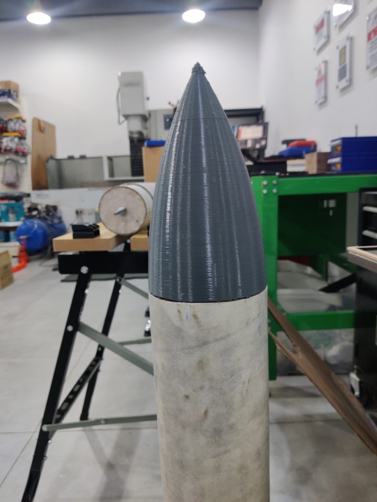
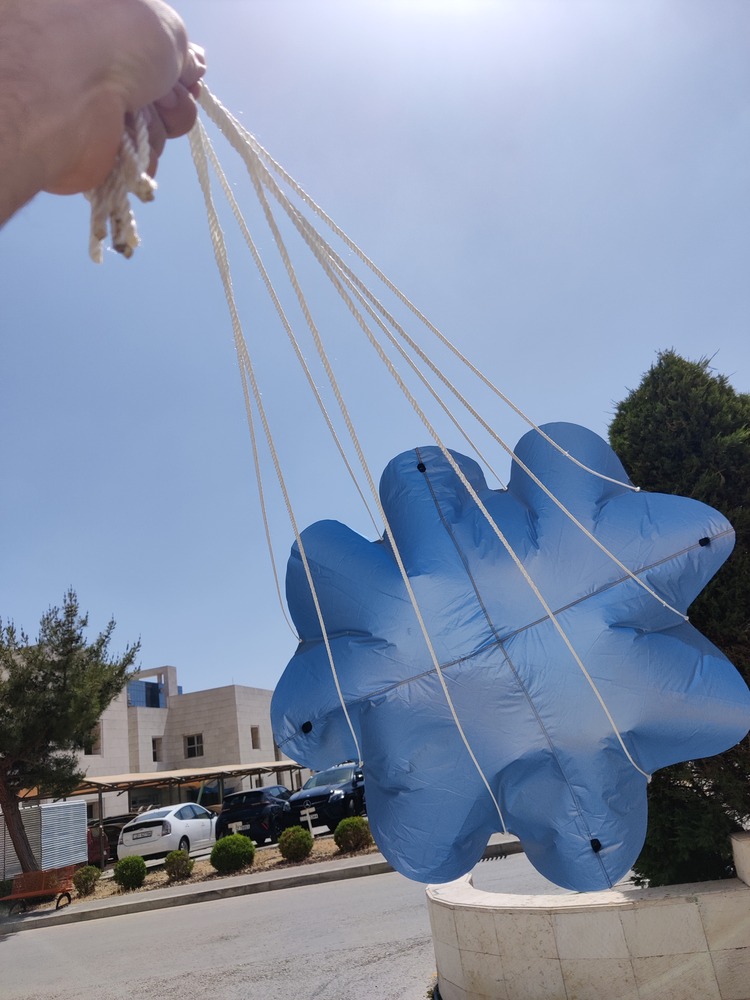
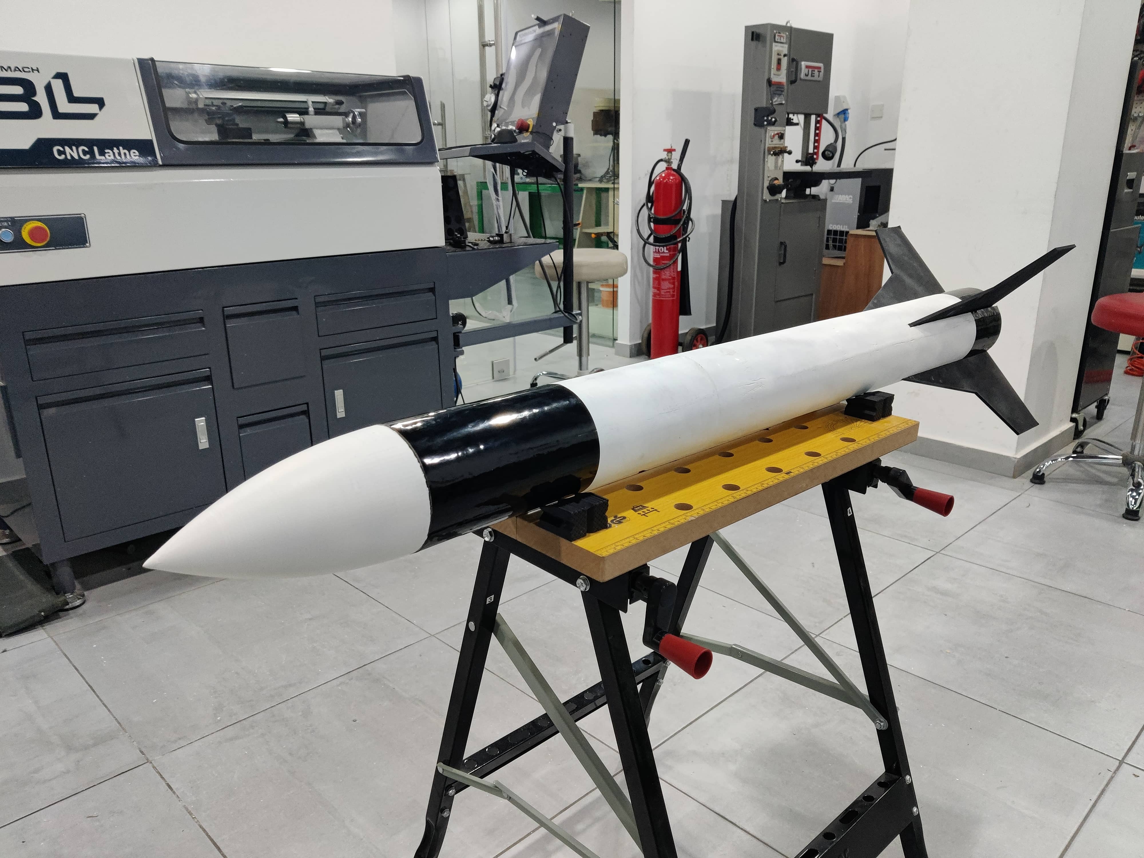
Hero Shot

Summary
This section outlines how the mechanical, electrical, and software components of the rocket are integrated into a cohesive and functional final product. The goal is to ensure that every subsystem is properly connected, securely packaged, and contributes to a professional, finished prototype.
Work Process Detail
🛠️ Mechanical Integration
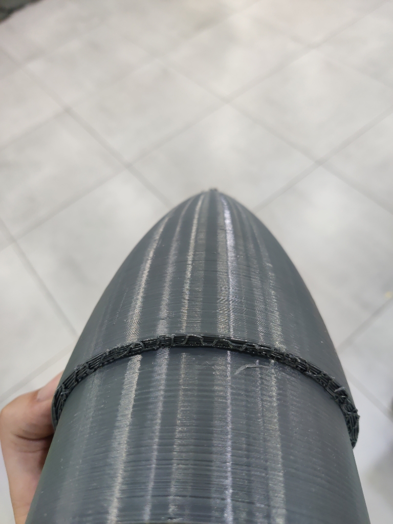
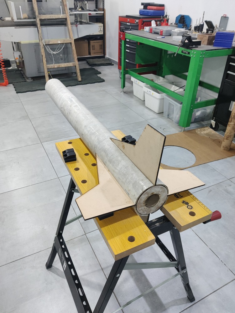
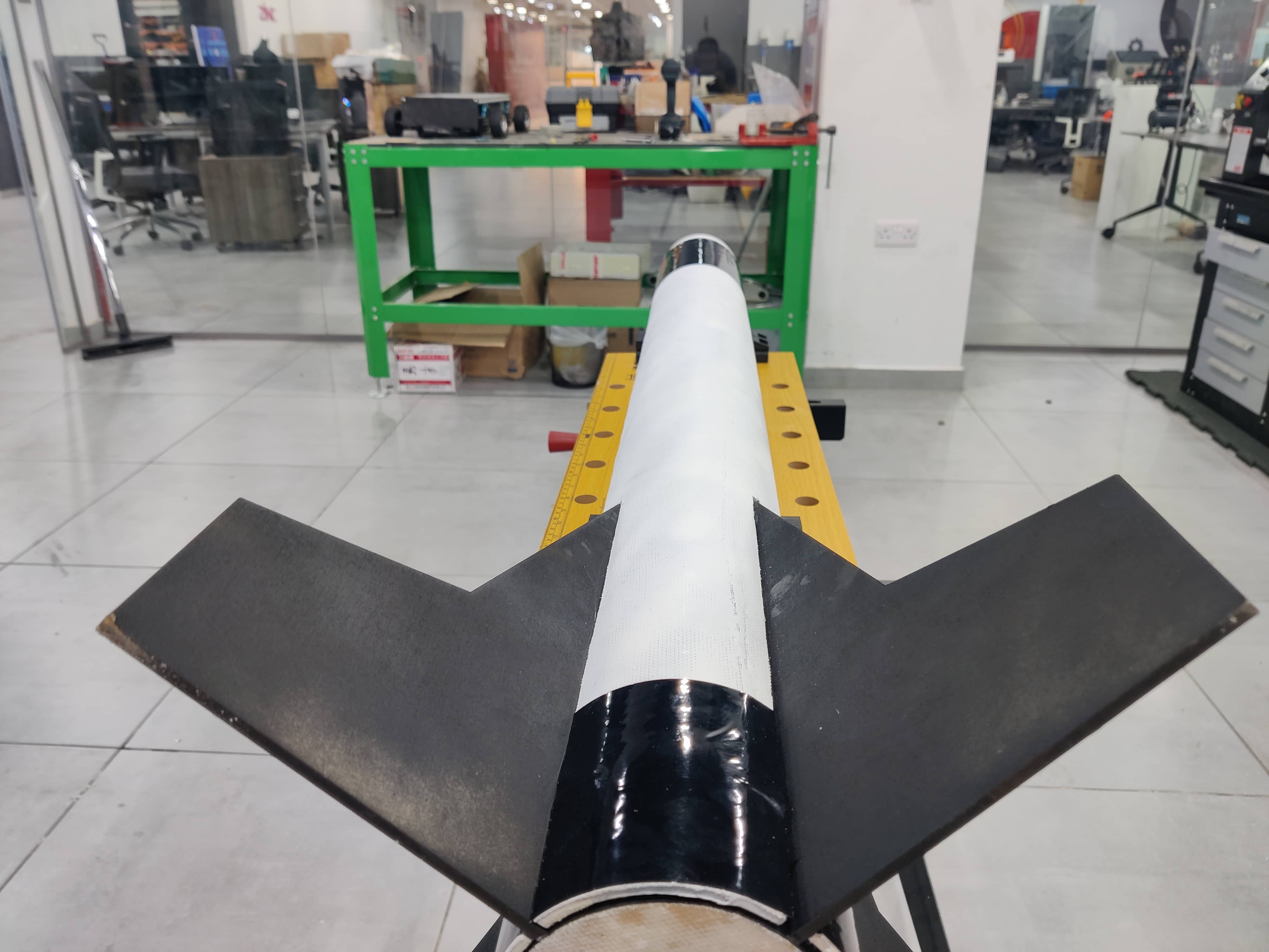
- Rocket Body Assembly
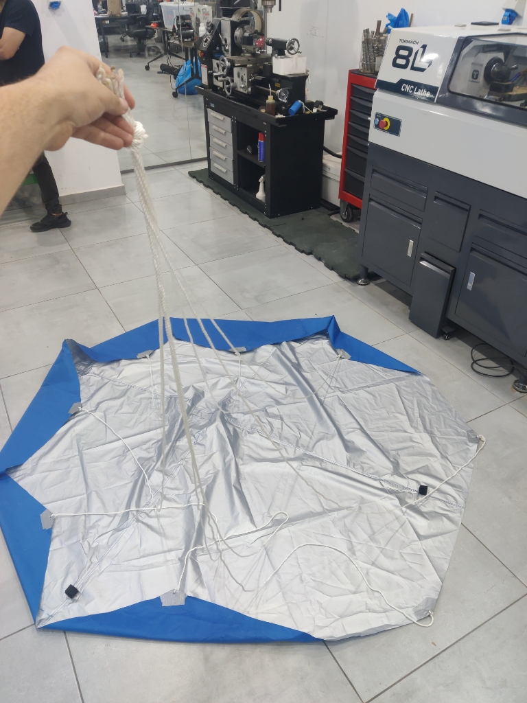
- Nose cone, payload bay, parachute.
- Mounting of Components
- barometer securely placed
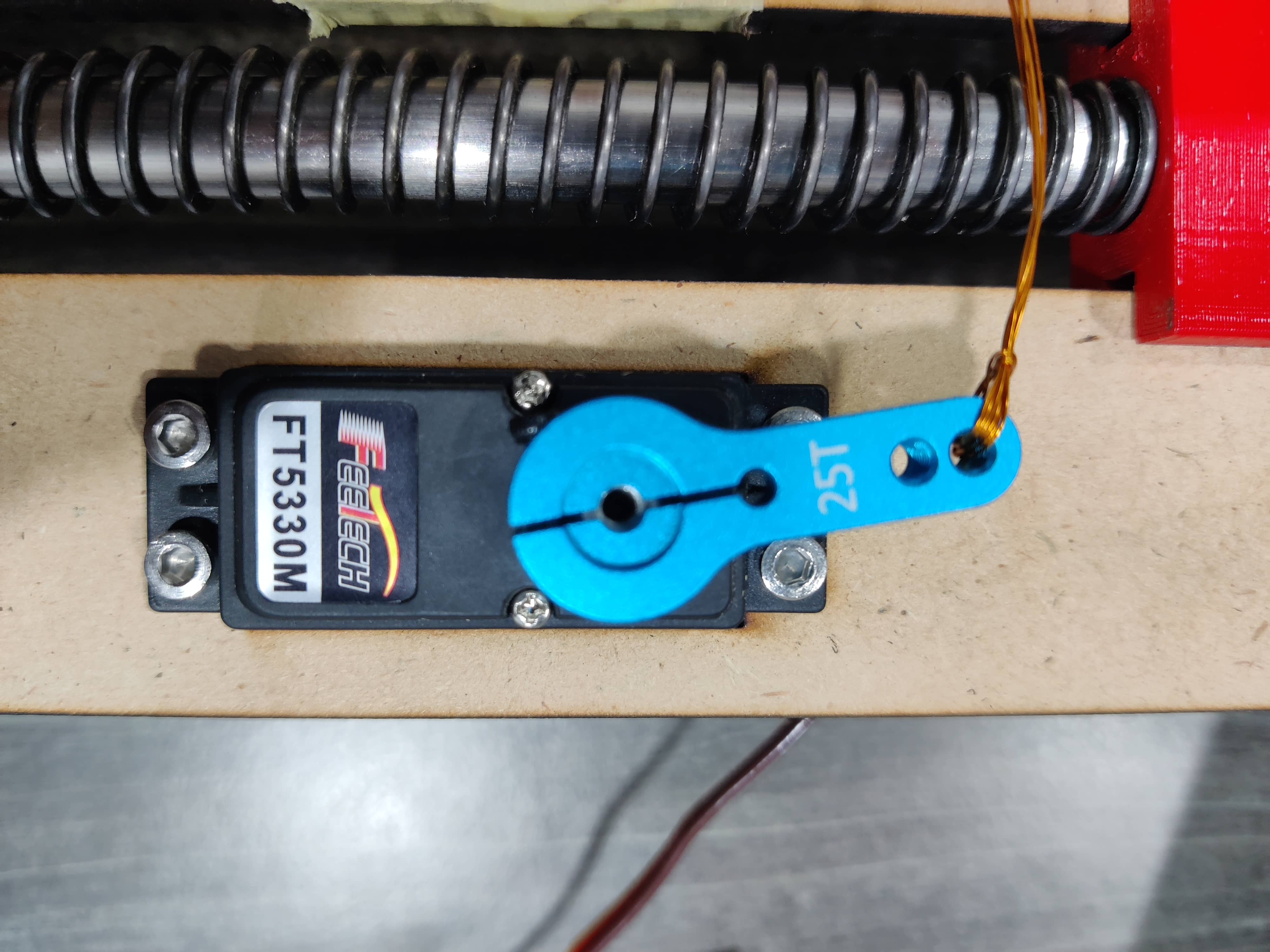
- Spring-loaded deployment bay with servo mechanism
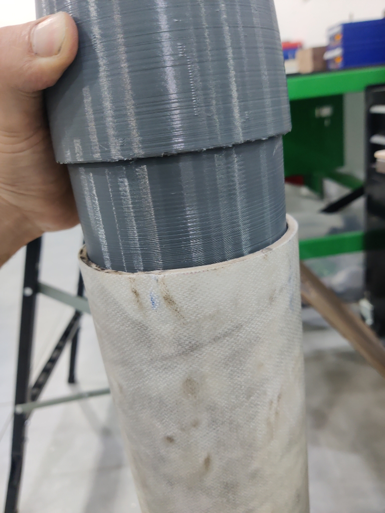
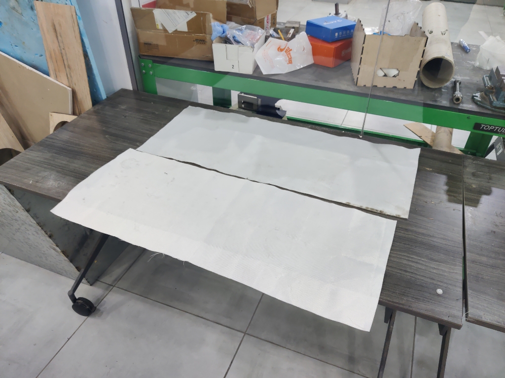
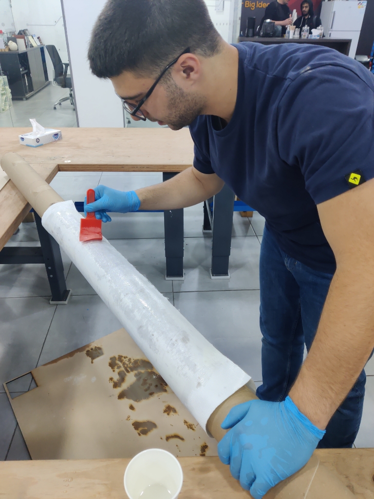
- Airframe Finishing
- Body tubes joined with precise couplers
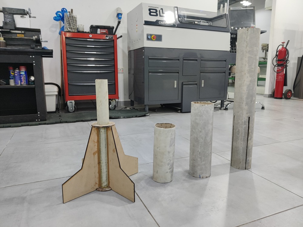
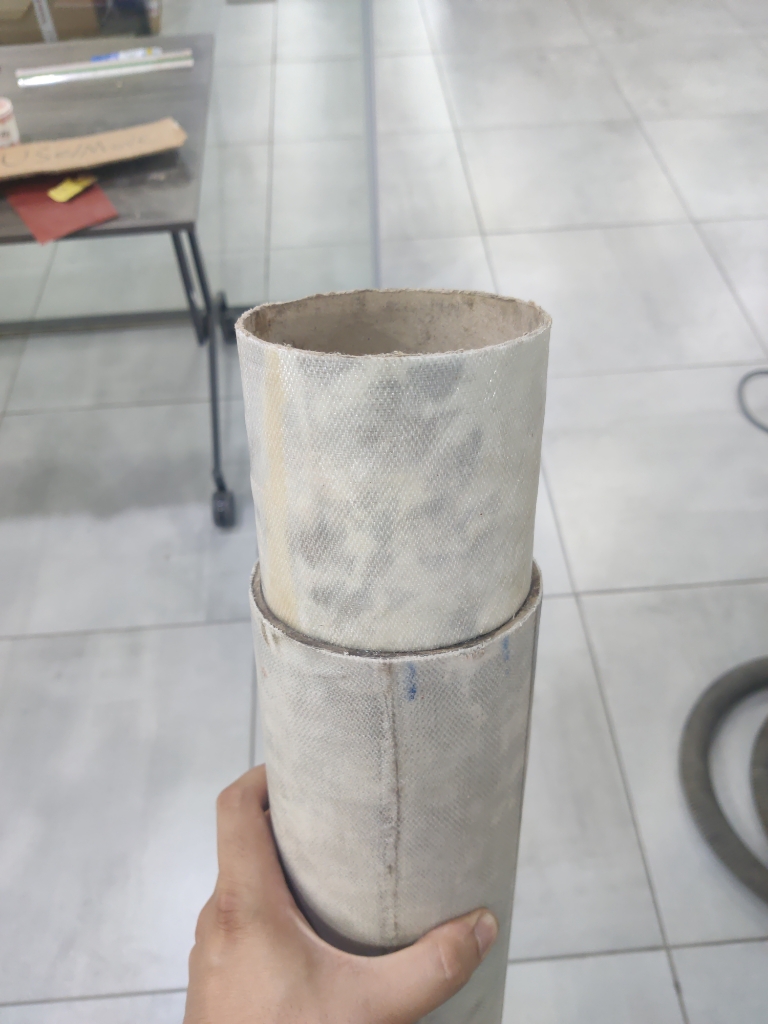
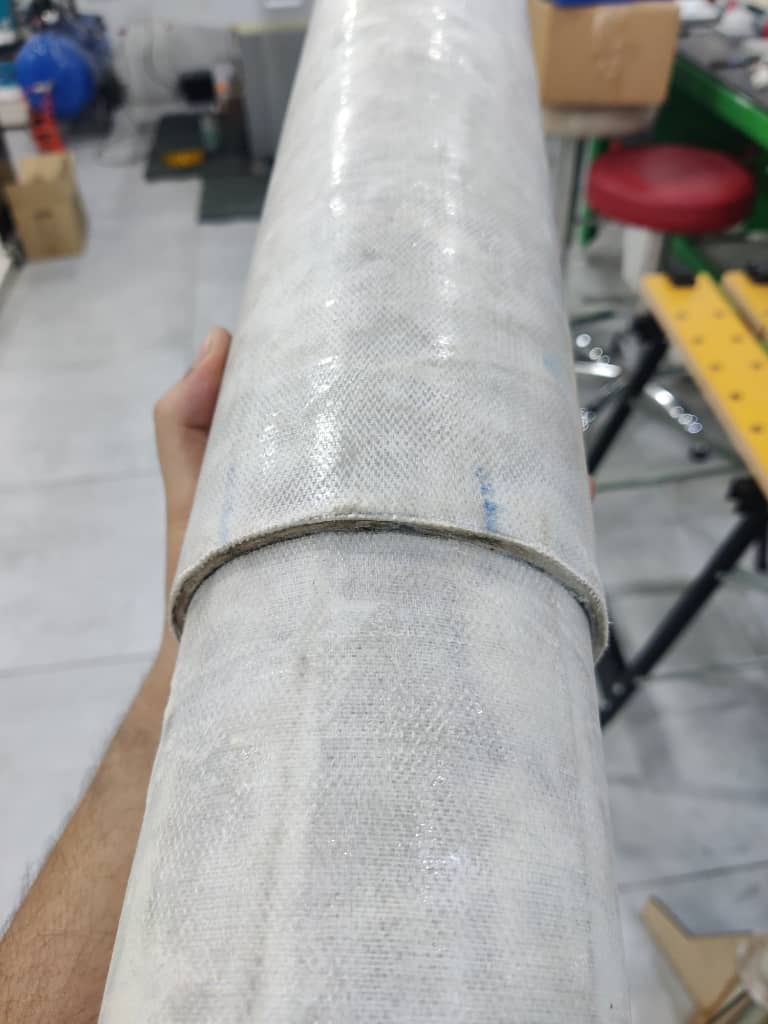
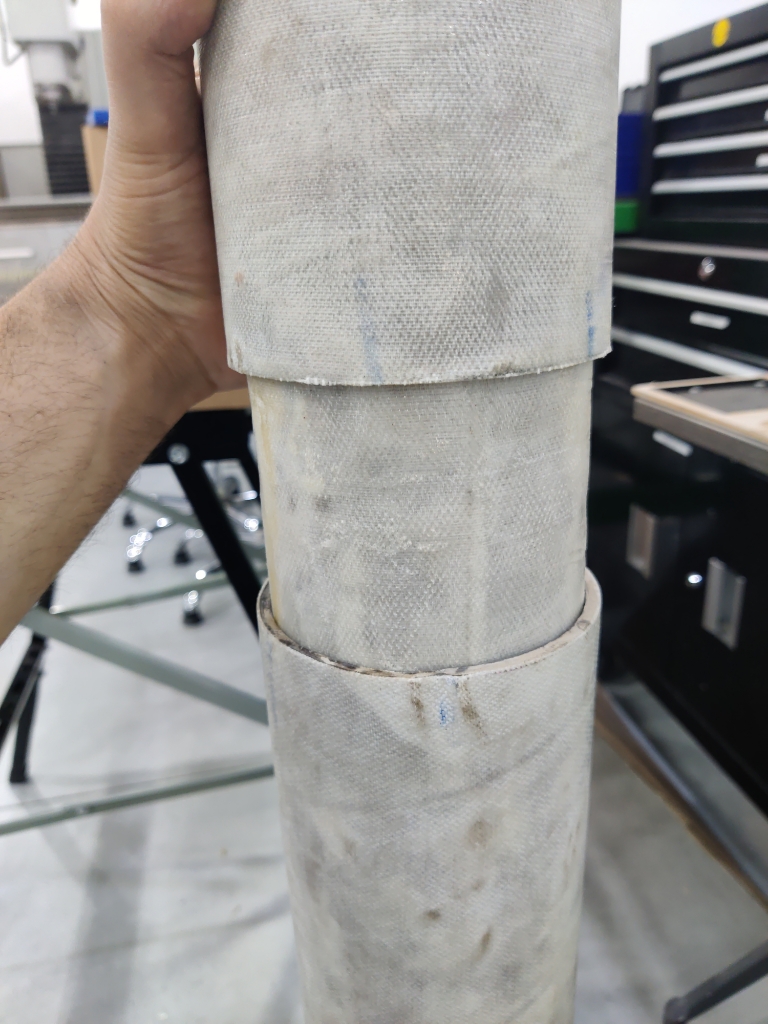
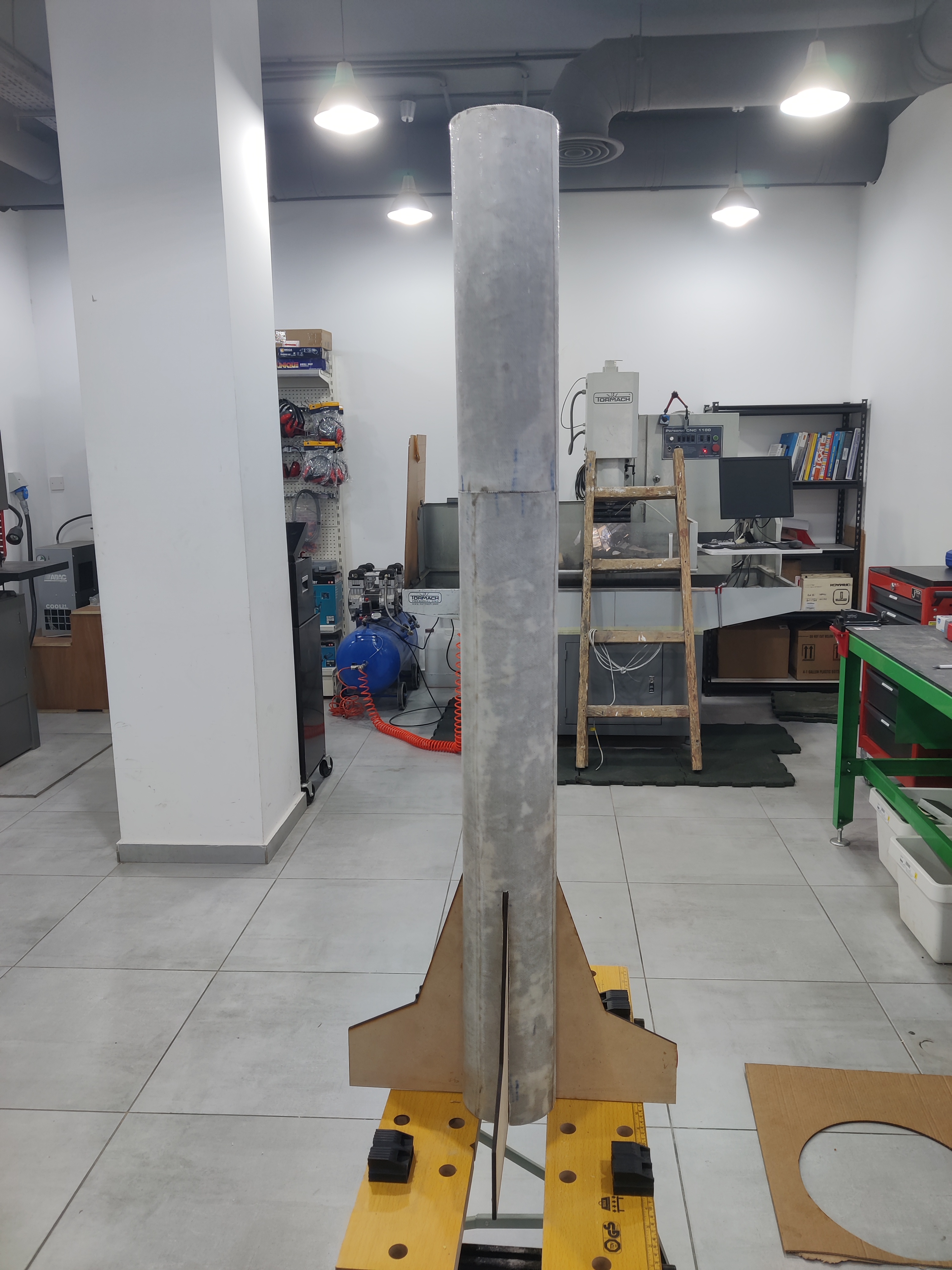
- Integration of fiber glass to reinforced parts
- Packaging
- Mechanical components housed in durable compartments
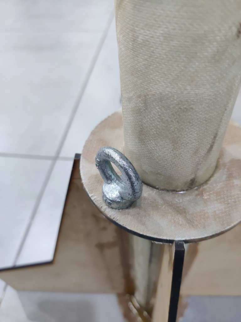
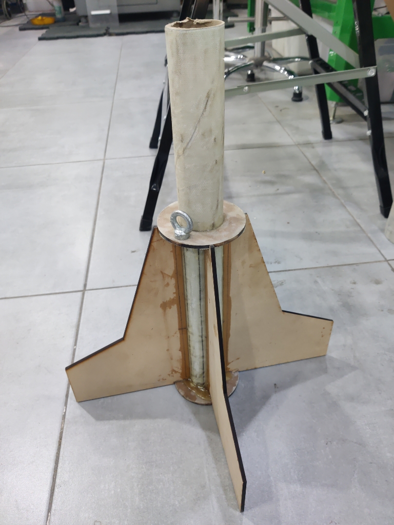
- Design ensures easy access for maintenance and assembly
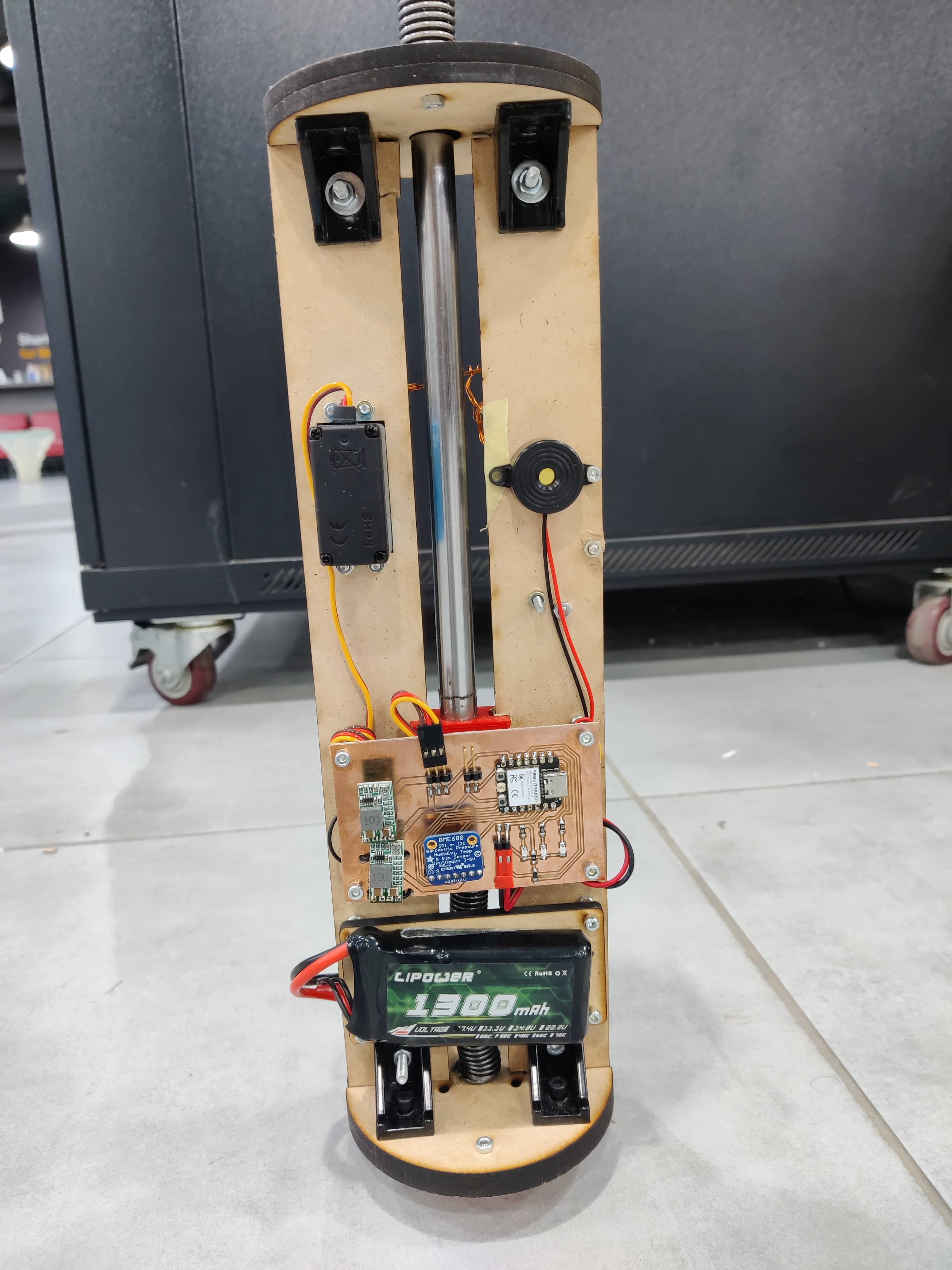
🔌 Electrical Integration
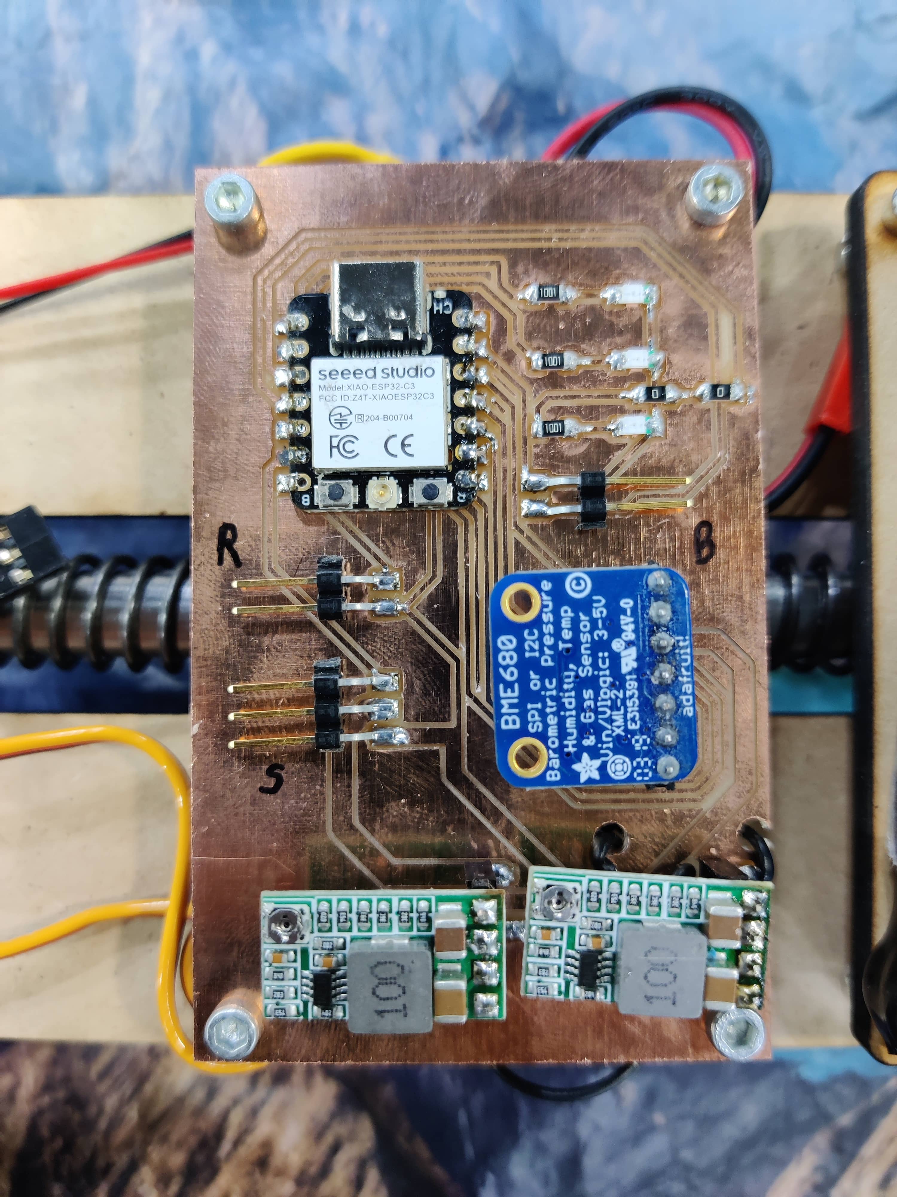
- PCB Design and Mounting
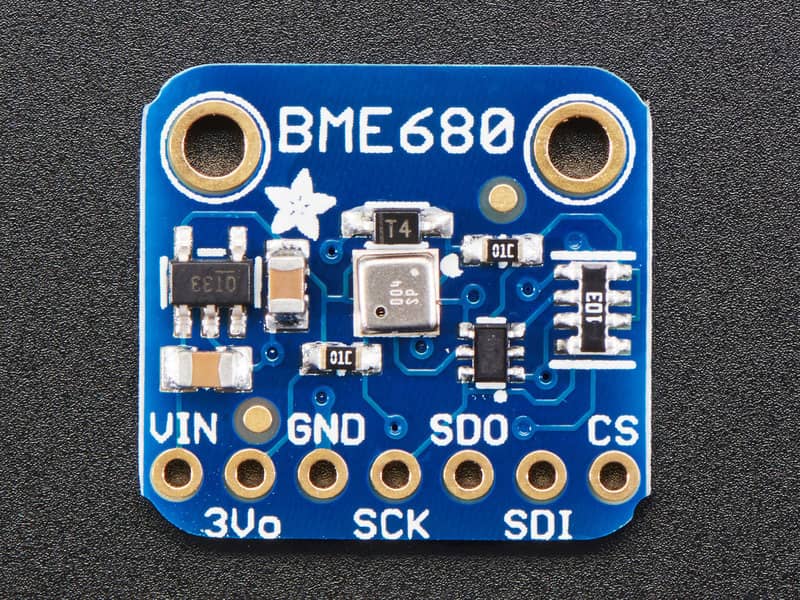
- Custom PCB with ESP32-C3, barometer (BME680), servo , buzzer.
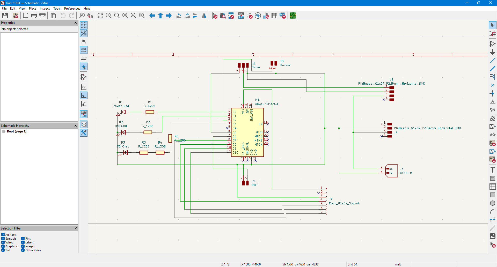
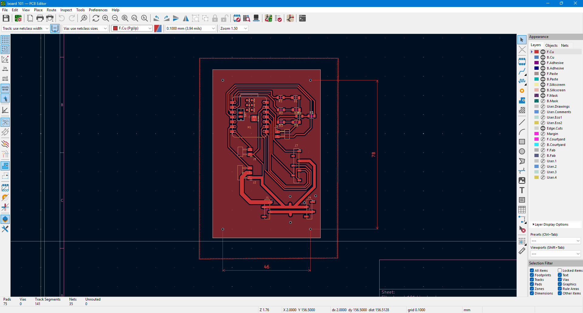
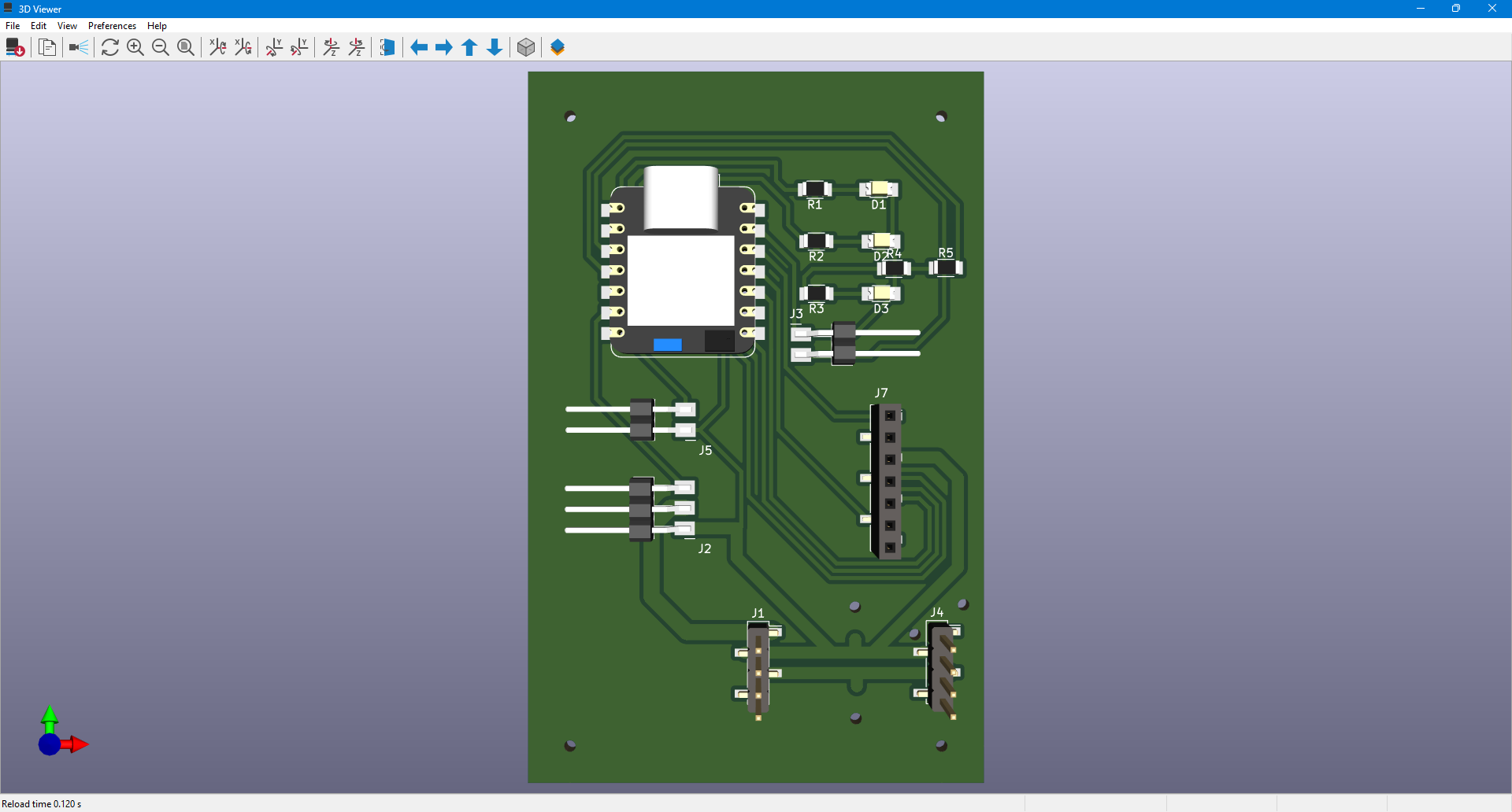
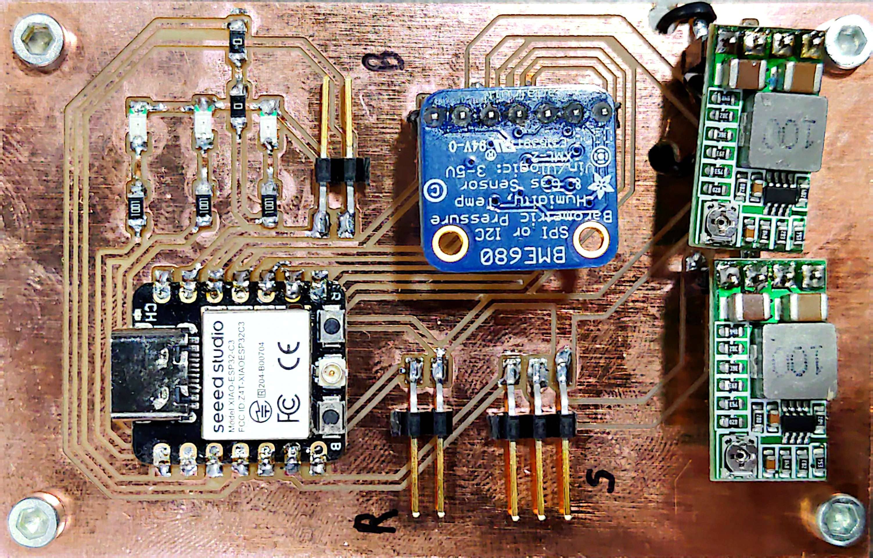
- Properly soldered components with labeled connectors
- Wiring and Connectors
- connectors and headers for modularity
- Heat-shrink tubing and cable management for durability and clarity
- connectors and headers for modularity
- Power Supply
- 7.4V Li-Po battery with voltage regulation circuit
- On/off switch and “Remove Before Flight” jumper trigger

- 7.4V Li-Po battery with voltage regulation circuit
💻 Software Integration
- Sensor
- Barometric sensor used to detect apogee
- Flight Sequence
System Logic:
1. Initialization (
setup()function)- Serial communication starts for debugging.
- Pin configuration is set:
RBF_PIN(Remove Before Flight pin) is input.
BUZZER_PINis output.
- Servo is attached and set to 180° (arming position).
- BME680 barometric sensor is initialized and configured for accurate altitude readings.
2. Waiting for Launch Preparation (
loop()function)RBF logic:
- The system waits until the
RBF_PIN(Remove Before Flight pin) is pulled LOW (i.e., shorted or pulled to GND).
- Once detected:
- The current time is recorded in
rbfRemovedTime.
- The buzzer beeps once to confirm the system is armed and entering delay.
- The current time is recorded in
3. 2-Minute Arming Delay
- After RBF is removed, the system waits 2 minutes (120,000 ms).
- During this time, nothing else happens—this is your safety delay before launch.
4. System Starts After 2 Minutes
- After 2 minutes, the system:
- Beeps again
- Prints altitude to Serial Monitor for testing
5. Real-Time Flight Logging
- On every loop:
- The BME680 reads pressure.
- Altitude is calculated using the standard barometric formula.
- Altitude is printed on the serial monitor.
6. Apogee Detection (Key Logic)
- The code checks if the rocket is still gaining altitude.
- If altitude keeps increasing, it keeps updating
apogeeAltitudeandapogeeTime.
- Once altitude stops increasing for more than 2 seconds:
- Apogee is confirmed.
- Servo is activated → rotates from 180° to 0°, releasing the parachute.
deployed = trueis set.
7. Landing Detection
After deployment:
- The code monitors the altitude readings:
- If the altitude is stable (±0.2 m) for over 5 seconds,
- It assumes the rocket has landed.
- The buzzer is triggered to continuously beep so you can find the rocket on the ground.
What the System Does (Full Timeline):
- Power ON → System waits for RBF pin to be pulled
- RBF pulled → 1 beep → 2-minute wait
- After 2 minutes → 2nd beep
- Rocket launches → Altitude increases
- Apogee detected (altitude stops increasing for 2 seconds) → Servo activates → parachute deploys
- Altitude stabilizes after landing → Continuous buzzer sound helps you locate it
📦 Packaging & Professional Finish
- Component Housing
- All internal parts securely fastened and protected
- Servo and deployment system integrated into central bay
- Cable Management
- Clean and organized internal layout
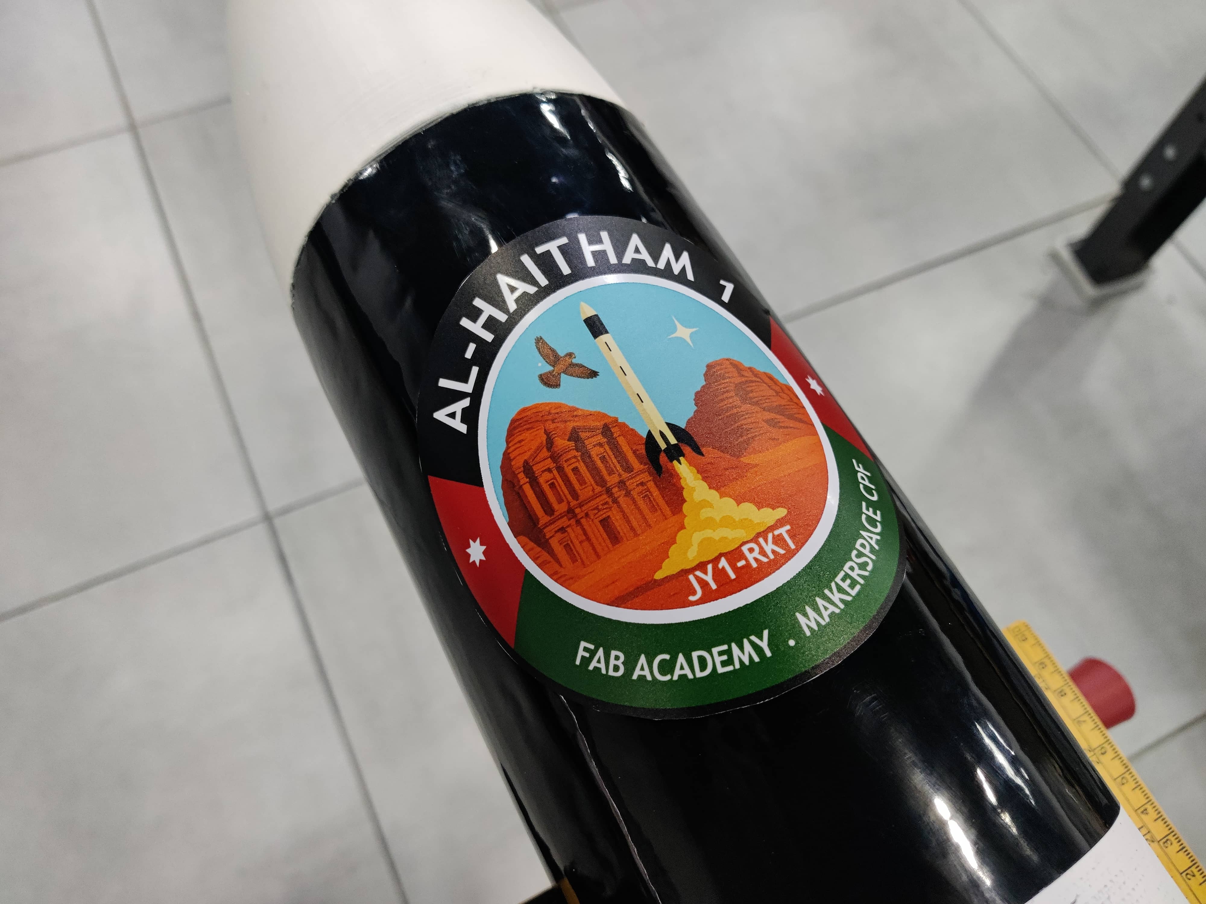
- External Finish
- Painted and labeled body, smooth aerodynamic surfaces
Learning Outcome
- Understood the principles of system-level thinking
- Practiced multidisciplinary integration (software + electronics + mechanical)
- Developed a product that mimics a real-world aerospace system
- Enhanced reliability and maintainability through modular and organized design