Week 13 - Molding and Casting
Group assignment:
• Review the safety data sheets for each of your molding and casting materials
• Make and compare test casts with each of them
• Compare printing vs milling molds
Individual assignment:
• Design a mold around the process you'll be using, produce it with a smooth surface finish that does not show the production process, and use it to cast parts.
Group assignment
For this week’s Group assignment, I teamed up with my fellow Fab Academy buddy Haw Ren to explore molding and casting with materials found in our Lab.
The documentation for our Group assignment can be found here.
Group assignment reflection
This week’s Group Assignment was a fun one. I enjoyed making the molds and casting different objects with different materials. Mixing the liquids/powders together and watching them solidify is a satisfying experience. I am surprised that I felt this way because I used to find chemistry frustrating when I was in school. While we were not successful in casting the toy maul hammers (we got two half hammers instead), the experience of trying to make them helped me to understand how I could do it better the next.
INDIVIDUAL ASSIGNMENT
OVERVIEW
Since we did not manage to get a good toy maul hammer from our Group Assignment, I decided to give it another go with my Individual Assignment, this time applying the learning points from the Group Assignment.
What went wrong previously?
Before starting on my new toy maul hammer, I reviewed the following mistakes that were made during the Group Assignment:
• Thin channels - The liquid plastic is quite thick and viscous, and the thin channels made it difficult for the liquid plastic to flow through when poured into the molds. Having a channel that is very long may also cause the liquid plastic to harden and stop flowing before it filled up the mold. Widening the “funnel” where the liquid plastic enters is also a good idea.
• No registers for 2-part molds – We did not create registers for our molds, which may cause possible problems with alignment.
• Materials that did not suit design – The handle of our maul hammer could not bond together properly when using Snow Water-activated Gypsum Powder. It was explained to us that such materials are stronger in compression than in tension, thus if the cross-section is too narrow and thin, it would just break apart easily.
Knowing these now, I proceed to work on my new design.
Creating the new toy maul hammer model
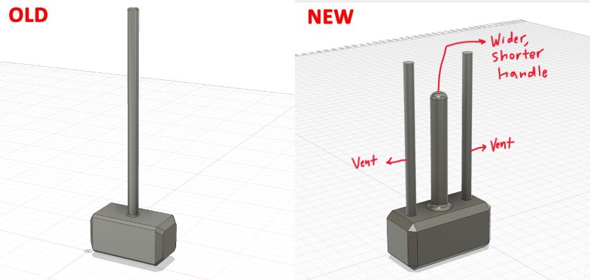
I start by modelling the new toy maul hammer, this time I make the following changes from the Group Assignment version:
1. Shorter and wider handle – I made the handle of the toy maul hammer a bit shorter and widened the handle diameter.
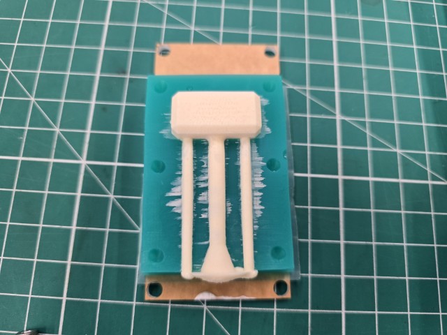
2. Added different vents – I also added two vents that will reach up to the level of the entrance pour hole. The intention is to have the liquid plastic overflow into these vents so that the liquid plastic can fully fill the cavity for the maul hammer head. These vents are meant to be cut off later.
Molding and casting workflow preview
Now that we have our new toy maul hammer design, it is useful to preview the molding and casting workflow before going further. The process is somewhat repetitive, and it can get confusing if you do not know whether you are creating the positive or negative parts. So here is the workflow preview:
3D Printed mold (Hard) > Silcone rubber mold (Soft) > Cast object (Hard) > Post Processing
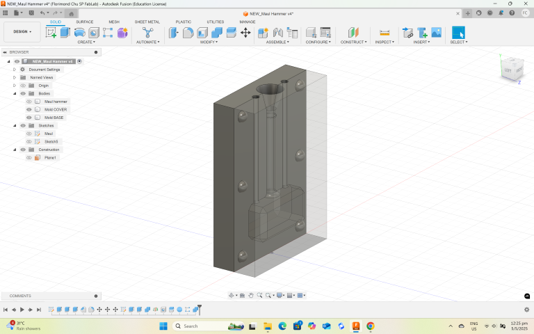
As seen above, the first thing I need is a 3D Printed mold to pour the silicone rubber mix into. Creating the model for the 3D Printed mold Here is a walkthrough of how I created the mold.
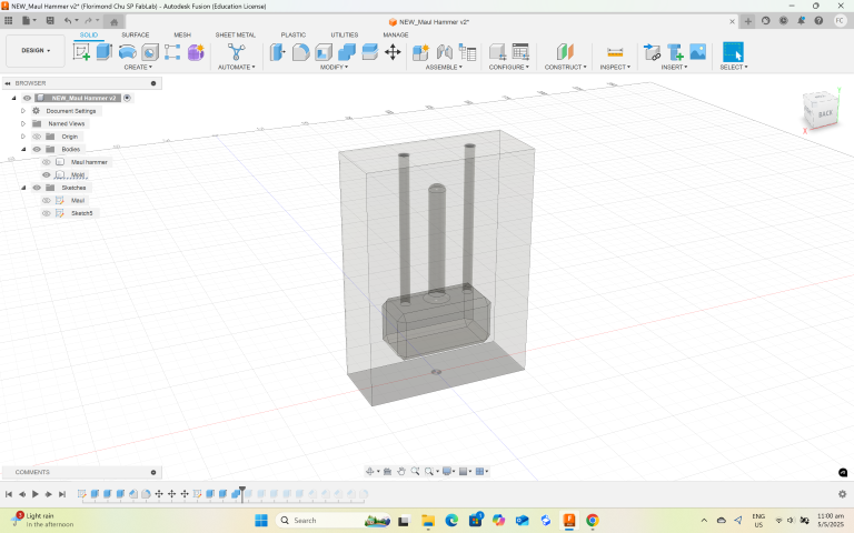
1. Create a box around the 3D model of the toy maul hammer
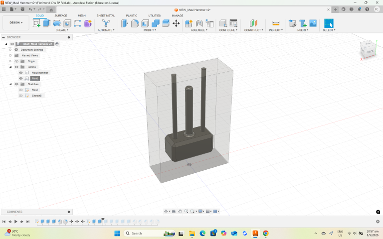
2. Using the toy maul hammer as a tool, use the Combine/Cut function to create the hammer shaped cavity
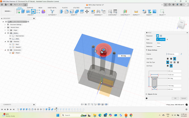
3. Use the Hole tool to create the hole/funnel where the liquid plastic will first enter the mold.
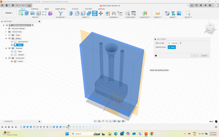
4. Use the Split Body function to cut the block into 2 halves
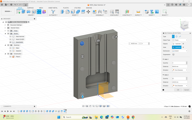
5. Create a shape to be the register. In my case, I used a sphere.
6. Use the rectangular pattern tool to propagate the registers along the mold
7. Use the Combine/Cut function to create the register cavities on the other side of the mold
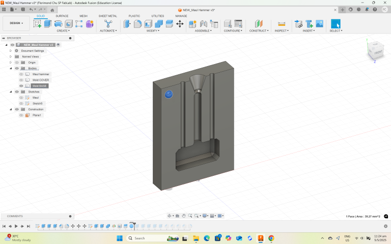
8. Move one half of the mold so that both halves of the mould are side-by-side.
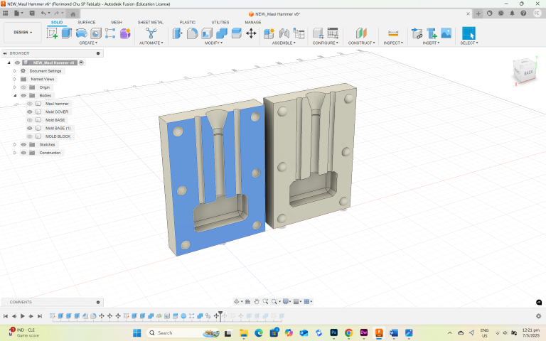
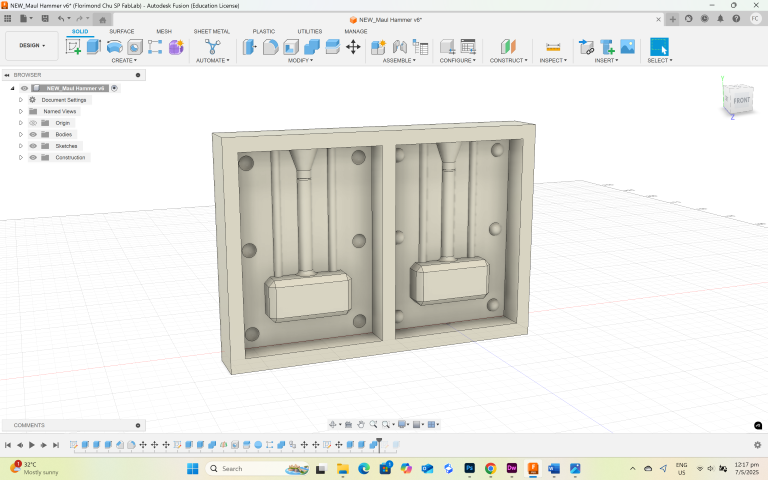
9. Create a box around the side-by-side molds, then use the Combine/Cut function (using the side-by-side molds as a tool) to carve out the mold cavity.
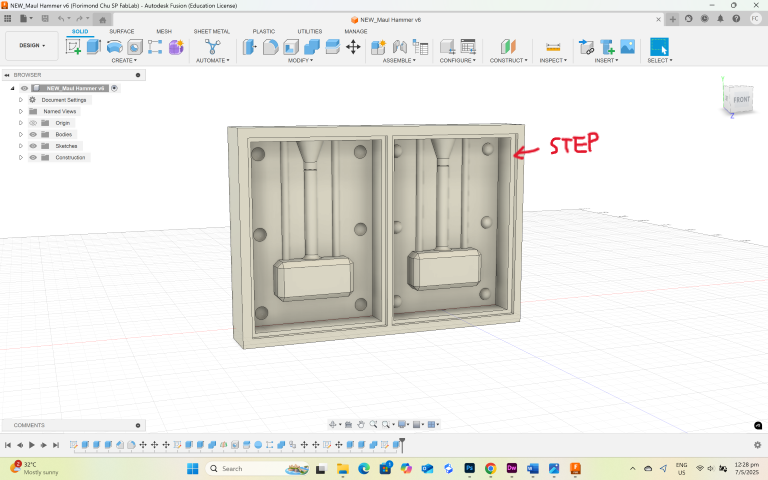
10. Lastly, add a small step around the mold to facilitate silicone extraction without using a knife or damaging the mold.
I watched this Youtube video on How to Create a Two-Part Mold in Fusion 360 by Product Design Online and it really helped me understand how to create the mold in Fusion 360.
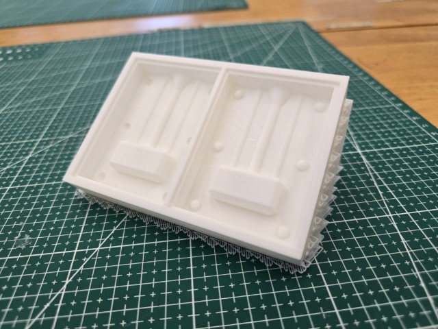
3D Printing the mold
With the mold model created, it is now time to 3D print the mold. Just like the Group Assignment, I exported the same mold model that was created in Fusion 360 to an STL format and 3D printed it out using our lab’s Bambu X1-C 3D printer.
To improve our chances of having a smooth finish, I printed our mold out using the best quality settings (0.08mm High Quality). I also printed it at a sloped angle as printing in this orientation can produce a smoother finish. As mentioned in the Group Assignment page, the disadvantage of this printing method is that uses more filament when printing this way because of the extra supports required. I also experienced a problem when attempting to 3D print this way. The 3D printing head seem to tear off a certain section of the print as shown in the photo below.
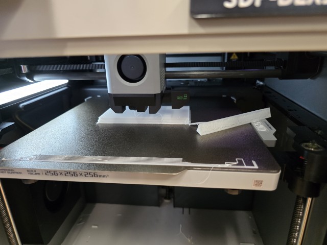
This happened twice and I had to restart the print each time. On my third attempt, I rotated my model (Z-axis) so that it was facing at an angle instead of facing straight to the 3D printer’s door. This worked and after a few hours, I have my 3D printed mold.
Creating the Silicone Rubber Molds
With my 3D printed mold in hand, I prepare to use BBDino Super Elastic Platinum Silicone Rubber which has the following properties:
| BBDino Super Elastic Platinum Silicone Rubber | |
|---|---|
| Mix Ratio | 1A:1B by Volume Or by Weight |
| Pot Life (Minutes) | 30 |
| Cure Time (Hours) | 4 |
The process for this part was:
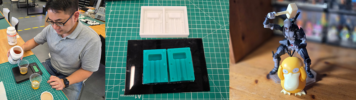
1. Measure out the required quantity of the unmixed material using a weighing scale. I poured water into the mold to estimate how much I will need. It is roughly a quarter cup of part A and a quarter cup of part B.
2. Pour the two parts together and mix them together thoroughly.
3. Place inside a vacuum pot to remove bubbles
4. Pour the mixture into the mold
5. Once the mixture is in the mold, leave the mixture to cure.
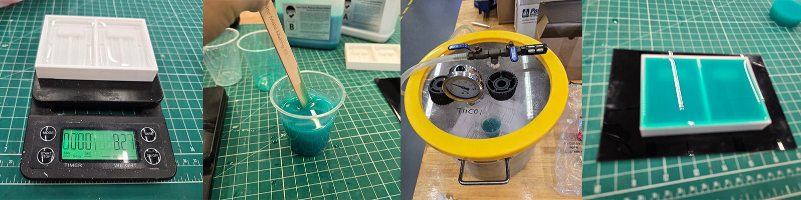
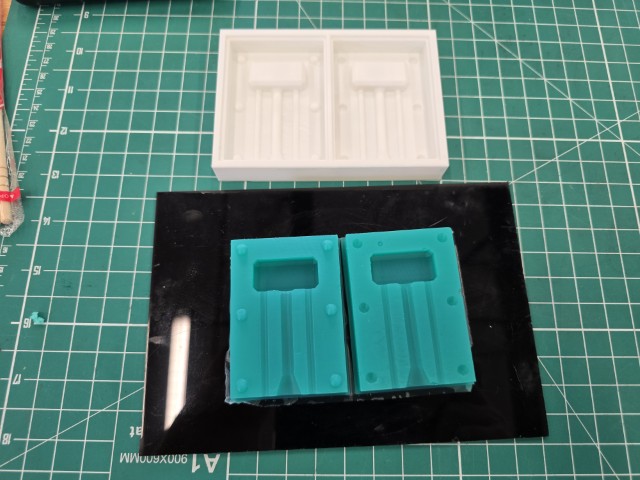
After curing the silicone rubber for a few hours, I have my silicone mold. I will be using this mold to cast my toy maul hammers.
Casting the Toy Maul Hammer
I use Polytek EasyFlo 90 Liquid Plastic as the material for the Toy Maul Hammer. It has the following properties that I noted before I started the mixing process.
| Polytek EasyFlo 90 Liquid Plastic | |
|---|---|
| Mix Ratio | 1A:1B by Volume 100A:90B by Weight |
| Pot Life (Minutes) | 5 |
| Cure Time (Minutes) | 60-120 |
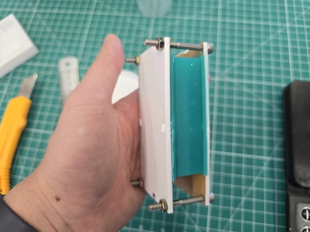
Before mixing, I also clamp the two halves of the mold together, sandwiched between two acrylic sheets held together by M4 screws and bolts.
I measure out the liquid plastic carefully by weight (100A:90B by Weight). In this case, I use 34g of A and 30g of B.
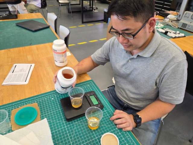
Then I mix and pour the mixture into the mold as seen in the video here.
After around 2 hours, I open the mold and the toy maul hammer has been successfully formed.
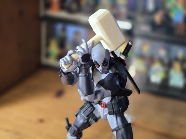
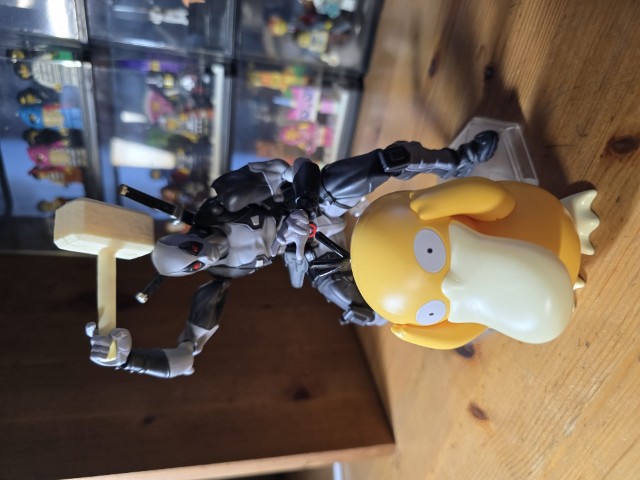
Post-processing and fun shots
I cleared off the excess plastic with nippers and sanding sticks that I use for model kit building. Here are some fun shots of the toy maul hammer.
Reflection
This week’s assignment was fun to do. The process of molding and casting reminds me of the movie Inception in that you make a mold to cast a mold which in turn is then used as a mold to cast the required object. I love the feel of my toy maul hammer but admit that I could sand/polish more if I had more time. I will definitely be doing more molding and casting in the future now that I have learnt this skill.
Design Files
This concludes this week’s assignment.