The primary goal of testing the 3D printer’s design rules is to evaluate and calibrate its
performance across various parameters that affect print quality, structural integrity, and functionality.
This process helps to:
Identify Limits and Capabilities: Determine the finest details, maximum overhangs, and bridging
distances the printer can handle without additional supports.
Optimize Settings: Fine-tune parameters like layer height, print speed, retraction, and cooling to
balance speed, accuracy, and quality.
Ensure Consistency: Verify dimensional accuracy, extrusion uniformity, and layer adhesion to produce
reliable parts.
Diagnose Issues: Detect problems like stringing, warping, under/over-extrusion, or poor bed adhesion
early on, allowing us to adjust settings or maintenance routines.
Improve Design Decisions: Inform future 3D model designs by understanding tolerances, fit, and the
need for supports or rafts.
By conducting these tests, we can create a baseline for our printer’s performance, which is especially
useful when switching between the MakerBot Z18 and Ender 3 or when troubleshooting print failures.
Analysis of our Test Setup and Results
Based on the settings we provided for the Ender 3 printer and the image of the output, here’s an evaluation
of our test and its implications:
Printer and Material
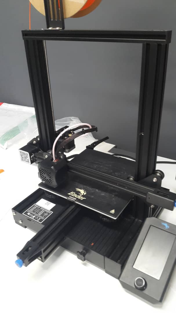
Printers Used: We tested the Ender 3 printer for this activity, though we also had access to the MakerBot
Z18 earlier. The Z18 was used to print the hard hat for Keipopele's individual assignment prior to this activity, but
it was unavailable during the test itself. Consequently, only the Ender 3 was used. The Ender 3 is a popular open-source
printer known for its affordability and versatility, while the MakerBot Z18 is a more industrial-grade printer with
potentially higher precision. If the Z18 had been operational, comparing its results with those of the Ender 3 could have
highlighted differences in build quality and performance.
Material: We used PLA (Polylactic Acid), a common, easy-to-print filament known for its low warping and good
layer adhesion, making it an excellent choice for my initial tests. However, it requires adequate cooling and can
be prone to stringing if our retraction settings are not optimized.
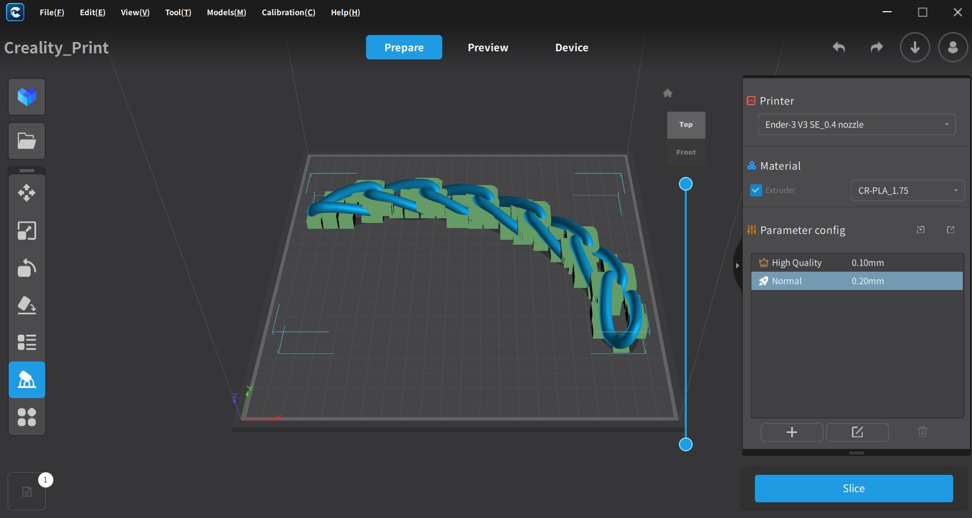
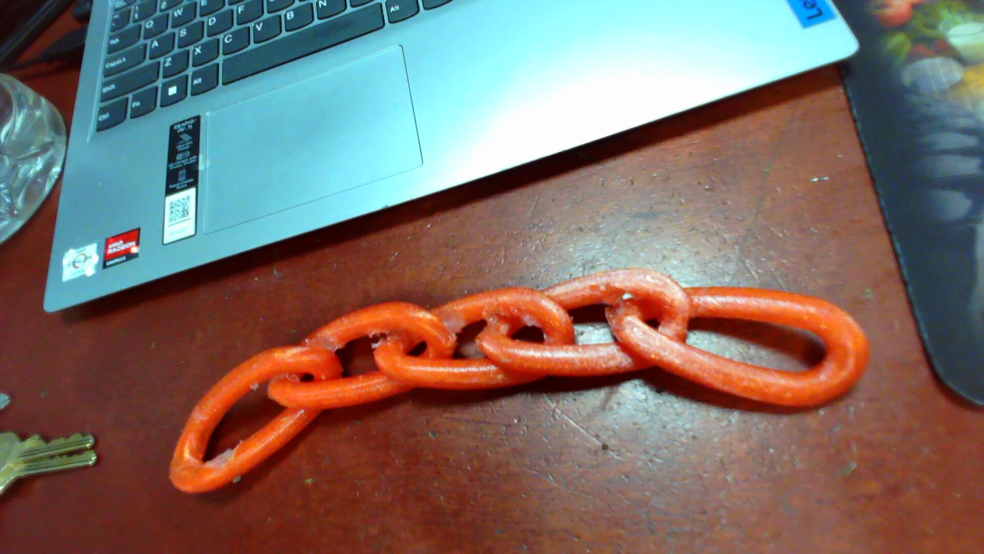
3D Printer Test Model
Settings and Observations
Minimum Layer Height (0.32mm):
This setting determines the thinnest layer the printer can produce, impacting detail resolution. A 0.32mm layer height
is relatively high for fine details (typical ranges are 0.1mm to 0.3mm). The image displays a model with small features
such as pillars and arches. We need to evaluate if the 0.32mm height adequately captures the intended details for us.
Finer layers (e.g., 0.1mm) could enhance resolution but would extend our print time.
Print Speed (70 mm/s) and Travel Speed (100 mm/s):
The print speed is set to 70 mm/s, a moderate value that should balance quality and efficiency for PLA. The travel speed
of 100 mm/s is suitable for non-printing movements. The image indicates some stringing (thin filament threads), suggesting
that we may need to adjust our speed settings or optimize retraction for better results.
Overhang Angle (No Support Enabled):
Without supports, the model tests the printer’s ability to handle overhangs. The curved arch in the image, printed without
supports, serves as an effective test of bridging and overhang capabilities. We must assess if the arch maintains its shape
or exhibits drooping, revealing the maximum overhang angle our settings can achieve.
Bridging Capability (5mm Minimum Distance):
A 5mm bridging distance is set to evaluate the printer’s ability to span gaps. The image shows horizontal spans (e.g., the arch base).
We will examine these bridges to determine if they are smooth or sagging, potentially indicating a need for us to improve cooling or
reduce speeds during bridging.
Extrusion Accuracy (Flow Rate 100%):
The flow rate is maintained at 100%, the default setting, though over-extrusion (excess filament) or under-extrusion (gaps) may occur.
The image reveals uneven surfaces and possible over-extrusion around pillars and arches. We will measure the printed parts against the
design to confirm accuracy for our project.
Dimensional Accuracy:
This assesses how closely printed dimensions align with the design. We can use calipers to measure features such as pillars and holes
in the image. Deviations (e.g., undersized holes or oversized parts) would suggest adjustments to scaling or calibration are needed for us.
First Layer Adhesion:
The image shows the model on a wooden surface without a visible raft or adhesion aid. Poor bed leveling or adhesion could lead to warping or
detachment. We should inspect the base layer for uniformity and adhesion strength to ensure our print quality.
Cooling Efficiency (Fan Speed 100%):
The fan speed is set to 100%, which benefits PLA, particularly for small details and overhangs. The image’s features (e.g., thin pillars) should
benefit from this setting, though excessive cooling may cause layer splitting. We will assess if the details are crisp or brittle for our evaluation.
Tolerance & Fit:
The model includes parts that may interlock (e.g., cylindrical pegs and holes). We will test if these fit with the intended clearance. The image suggests
some parts might be slightly oversized or undersized, which we can verify with physical tests.
Stringing & Retraction (4mm at 25mm/s):
Retraction is set to 4mm at 25mm/s, a moderate configuration for PLA. The image displays some stringing (e.g., thin lines between features), indicating
potential adjustments to retraction distance (e.g., increasing to 5-6mm) or speed (e.g., slowing to 20mm/s) may be warranted for us.
Warping & Shrinkage (No Adhesion Aid):
PLA typically exhibits low warping, but without a heated bed or adhesion aid (e.g., glue stick or tape), the first layer might lift. The image shows no
obvious warping, though we should check the edges for slight curling to confirm our setup.
Material Compatibility (PLA):
PLA is used, which is compatible with both the MakerBot Z18 and Ender 3. This test confirms suitability for us, and the results will aid us in refining
settings for PLA-specific challenges (e.g., cooling, retraction).
Nozzle Clogging & Maintenance:
The printers are noted to be well-maintained. The image shows no obvious clogs, and consistent extrusion with clean surfaces suggests maintenance remains
effective.
Individual Assignment
3D Design & Printing
I was part of a team tasked with designing a more organic and comfortable hard hat equipped with sensors for monitoring temperature, pulse, and fatigue.
Using surface modeling in SolidWorks, I harnessed its organic modeling capabilities to create a natural, ergonomic fit tailored to the human head. The process
began with sketching splines and curves on the front and top planes to define the dome and overhang, followed by lofted and boundary surfaces to ensure smooth
transitions and precise contours.
Multiple surface-trim operations shaped the hollow interior and perforated rim—visible as a dotted pattern in the model—enhancing
ventilation and providing space for sensor integration. The maroon and blue color render was used to highlight the visibility of the overhang from the hat dome,
aiding in assessing the design's structure, with the model optimized for 3D printing on a MakerBot Replicator Z18, including considerations for overhangs and
support structures.
This surface modeling approach resulted in a lightweight, anatomically friendly hard hat, ideal for prolonged wear and sensor embedding. The use of advanced tools
like lofts, boundaries, and cuts allowed for a seamless design that balances comfort with practicality, while the perforated rim reduces weight and supports
airflow and sensor accessibility. The color-coded render enhanced the evaluation of the overhang's feasibility, ensuring a functional and printable design that
brings the innovative concept to life.
Include CAD screenshots and STL files.
I modeled the hat with a surface modelling in order to take advantage of the organic features in the solidwrks. These are necessary in producing materials
that will be in touch with body parts.
Surface Model
I coverted the solid works file into an STL file type in order for the 3D Printer to recognise it
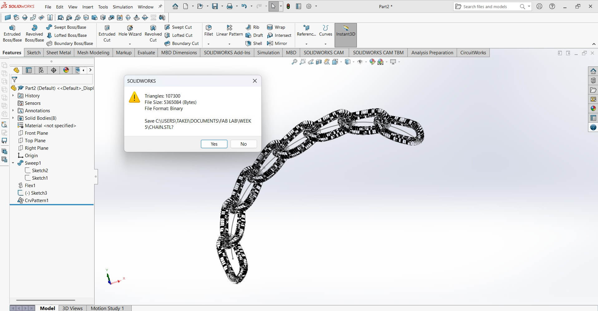
STL File Conversion
The picture below shows the hard hat printed on the Makerbot Z18 3D Printer
3D Printed Hat
3D Scanning & Printing
Expalining the Einstar 3D Scanner
Einstar 3D Scanner: Overview and Features
The Einstar 3D scanner, developed by Shining 3D, is a handheld structured light scanner designed for affordability and ease of use while maintaining
high-quality scans. It is suitable for makers, engineers, designers, and researchers who need a portable and efficient scanning solution.
Key Features
Structured Light Technology: Uses infrared structured light for precise scanning, reducing the impact of ambient light.
High Accuracy: Achieves up to 0.1mm accuracy, making it suitable for capturing fine details.
Full-Color Scanning: Supports texture capture, making it useful for digital modeling, art, and gaming applications.
Large Scanning Area: Covers a wide field of view (200×100mm to 1000×1000mm), making it suitable for both small and large objects.
High-Speed Capture: Scans at a speed of up to 14 frames per second, improving workflow efficiency.
No Markers Needed: Unlike laser scanners, Einstar can capture objects without requiring reference markers.
Connectivity: Uses a USB-C interface for fast data transfer to a computer.

Applications
Reverse Engineering: Capturing existing parts for CAD modeling.
3D Printing: Scanning objects to create replicas or modify designs.
Heritage Preservation: Digitizing artifacts and sculptures.
Medical Applications: Creating prosthetics and orthopedic models.
Game Development & AR/VR: Capturing real-world objects for 3D environments.
Explain the scanning process, tools used, and any modifications applied.
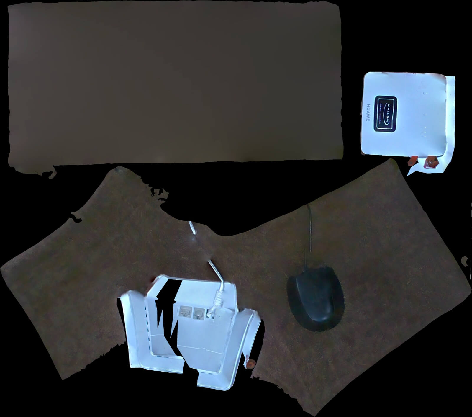
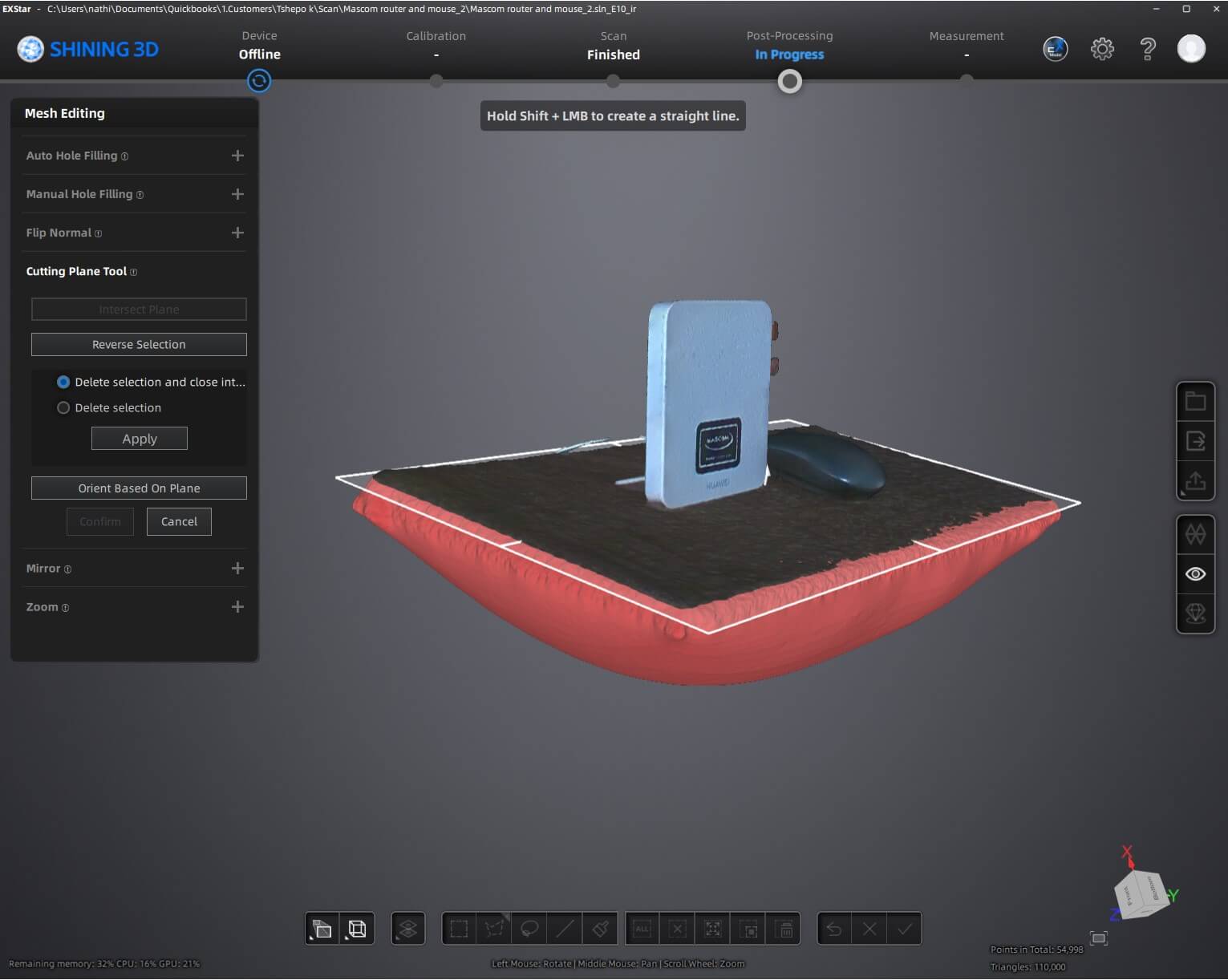
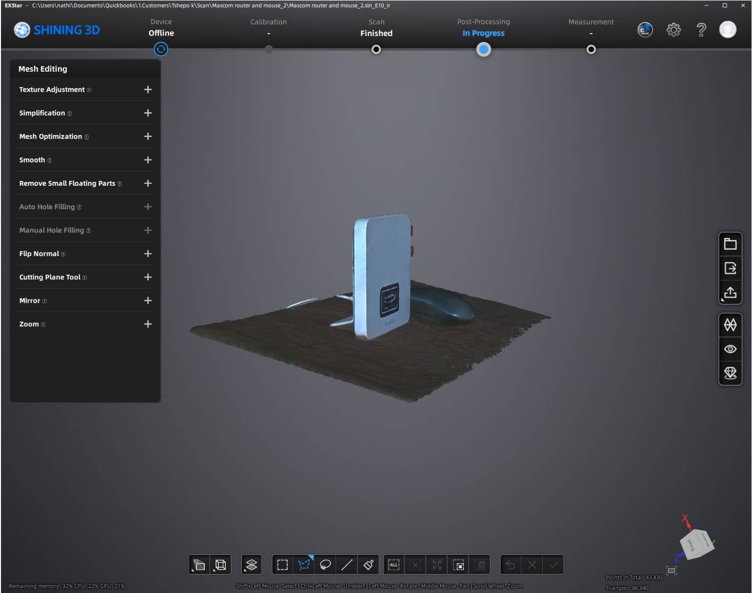
The scanning process was done on a Huewei and a computer mouse.It happened by scanning the object by moving the handheld scanner
around it to capture its geometry.
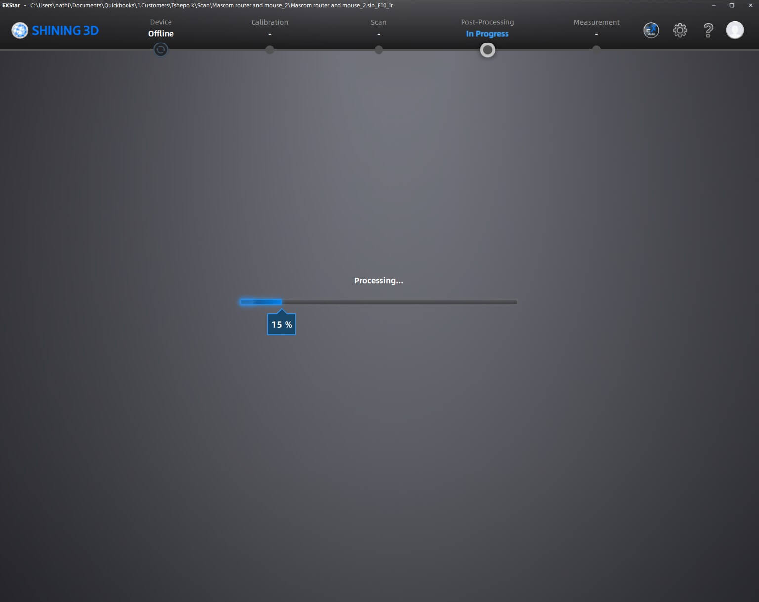
The scanning process on software
3D Scanning Process, Tools Used, and Modifications
Scanning Process
The 3D scanning process involves capturing the shape, texture, and dimensions of a physical object to create a digital
3D model. The Einstar 3D scanner follows these key steps:
Ensure the object is well-lit and free from reflections or transparent surfaces that may interfere with scanning.
Position the object on a stable surface or rotating turntable for even coverage.
Scanning:
The Einstar 3D scanner projects structured infrared light onto the object.
The scanner’s sensors capture distortions in the light pattern to reconstruct the object's shape.
The scanner collects multiple frames in real time, aligning them automatically.
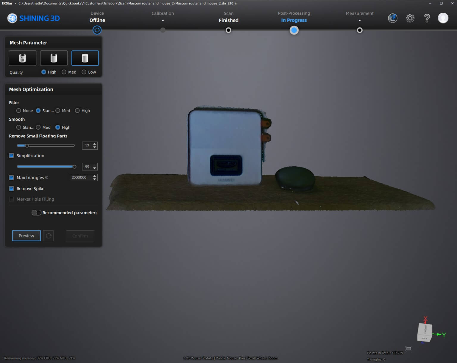
Processing & Refinement:
Alignment & Merging: If multiple scans are taken from different angles, the software aligns and
stitches them together.
Noise Reduction: The software removes unwanted data points or artifacts from the scan.
Mesh Generation: A watertight 3D mesh is created, defining the surface geometry.
Texture Mapping: If color capture is enabled, the scanned textures are applied to the model.
Tools Used
Einstar 3D Scanner: Captures the object's shape and texture.
Shining 3D Software (EXStar): Processes and refines the scan data.
Computer: Runs the scanning software and handles data processing.
Turntable (Optional): Helps with scanning smaller objects smoothly.
Lighting Equipment: Ensures optimal scan quality by reducing shadows.
Modifications Applied
Mesh Optimization: The model is simplified or smoothed to reduce file size while maintaining detail.
Hole Filling: If any areas were missed during scanning, they are interpolated and reconstructed.
Scaling Adjustments: The scan may be resized to match real-world dimensions.
Texture Enhancement: Colors and surface details may be adjusted for better realism.