Inventory Tracking System for Storerooms
This Fab Academy project automates tool and item management in storerooms, addressing inefficiencies and loss due to misplaced or untracked tools.
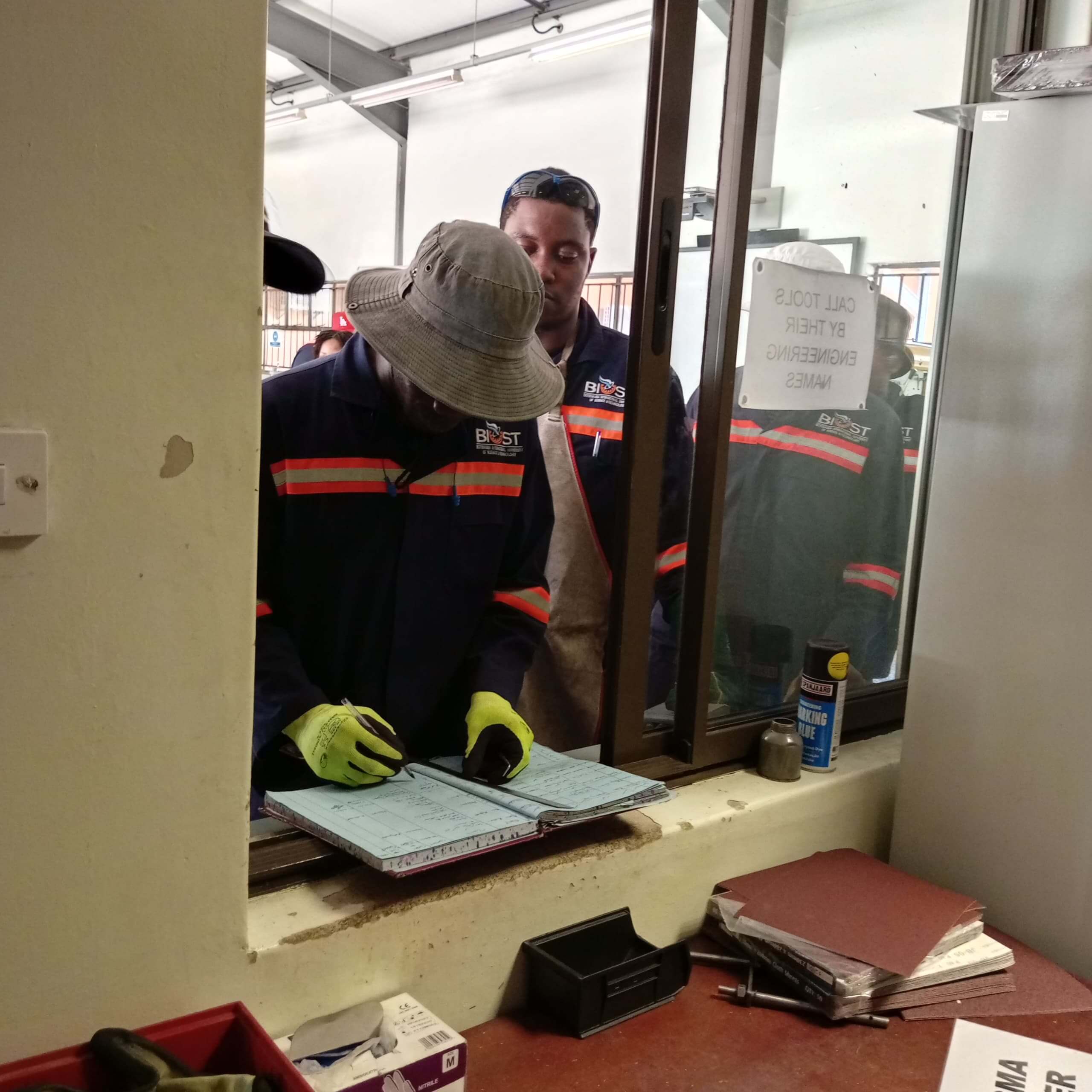
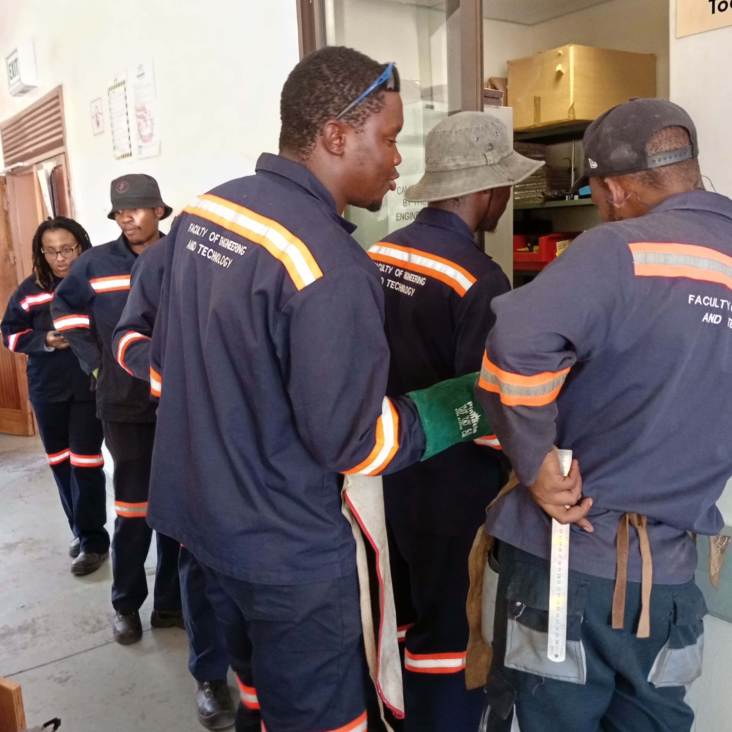
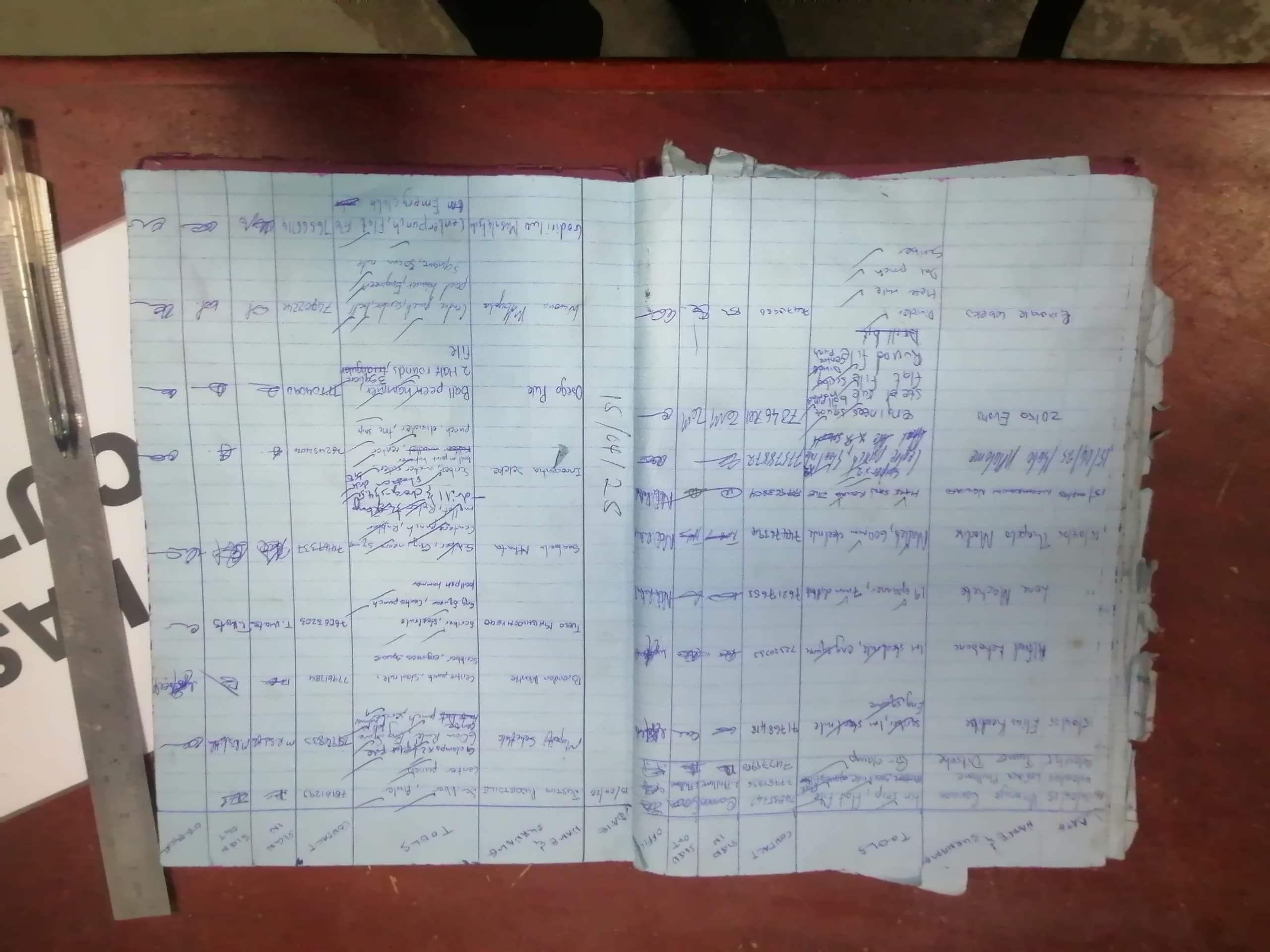
Problem
Tools in storerooms are often misplaced or untracked, leading to inefficiencies and loss. Manual tracking is error-prone and time-consuming.
Solution
The Inventory Tracking System automates tool management by:
- Scanning RFID tags using an RF Ideas RDR-7081AKU USB RFID reader to identify up to 20 tools.
- Registering borrowers via a second RFID scan (RFID-RC522) or manual UID entry as a redundancy plan.
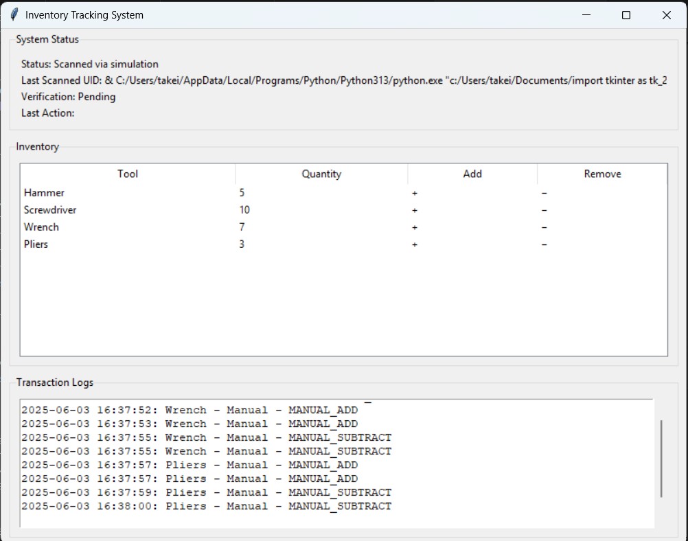
- Displaying real-time status, inventory, and transaction logs via a Tkinter GUI on a Raspberry Pi.
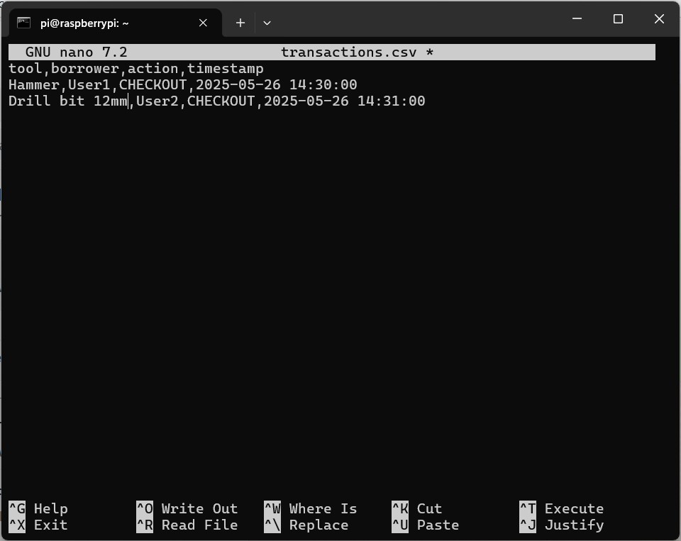
- Logging transactions (tool UID, borrower UID, timestamp, action) in a CSV file.
- Allowing quantity adjustments through GUI buttons.


This system enhances efficiency, reduces loss, and ensures reliability with a manual fallback if the RFID reader fails.
Prior Work
- Coding Techroom: Using RFID for Inventory Management with Java on Raspberry Pi.

CodingTechroom
- Medium: Building an RFID Reader and Display System with Raspberry Pi Zero W 2.
Medium
- EAL: RFID Inventory Management.
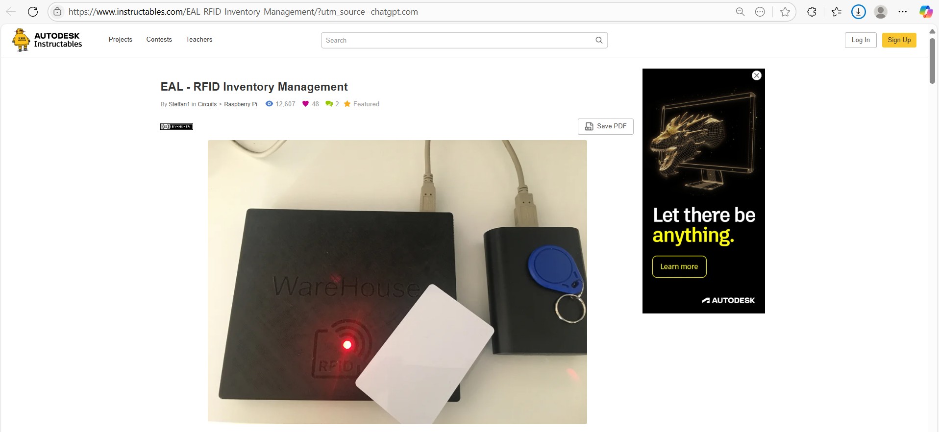
EAL_Inventory_Management
- My Prior Work: Implemented Tkinter GUI with serial communication and transitioned to RDR-7081AKU.
FabAcademy_Rwanda
Fab Academy Skills
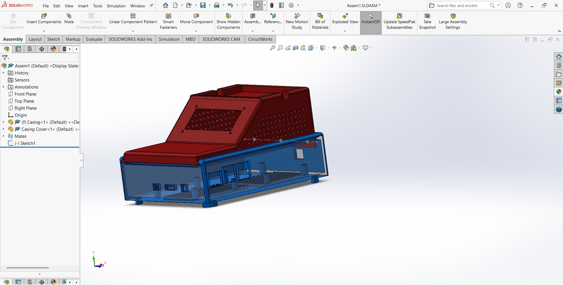
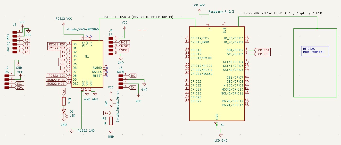
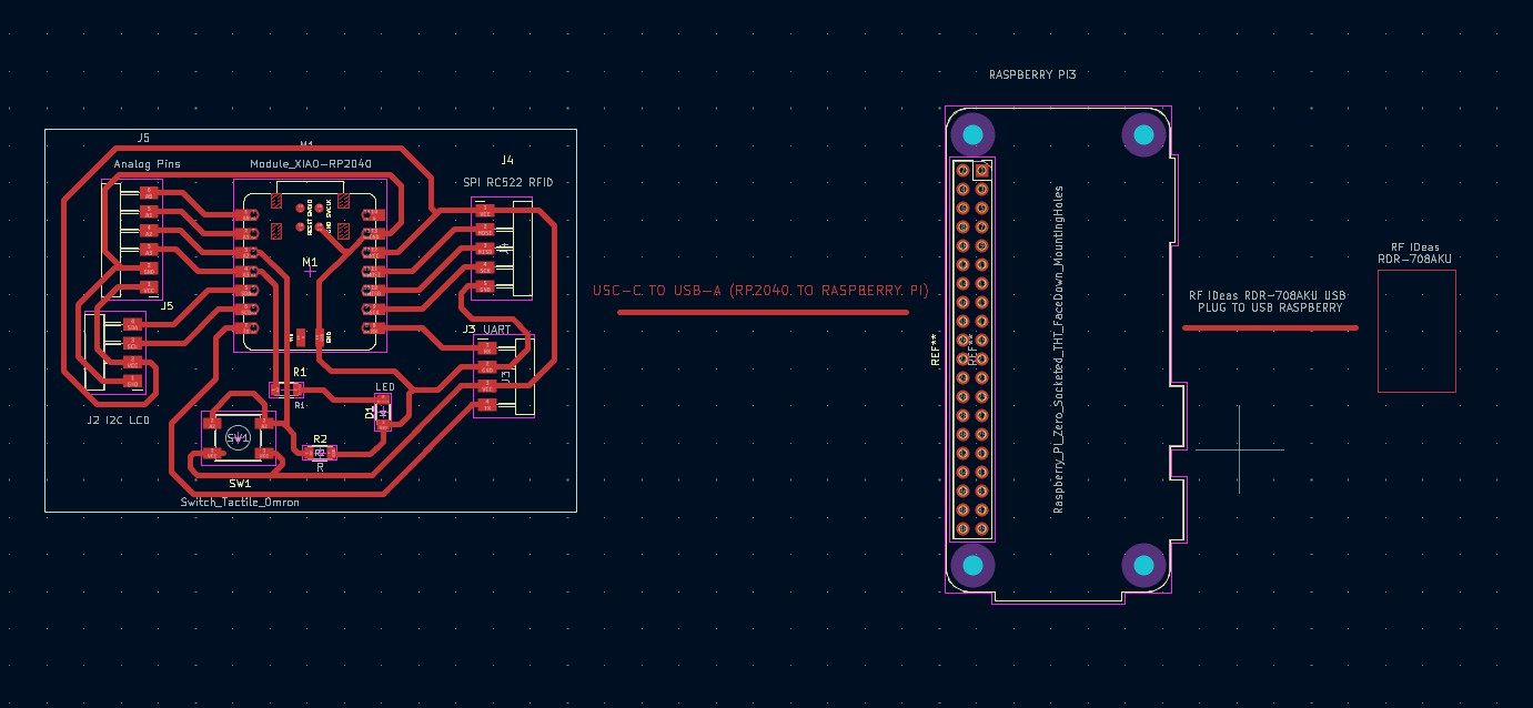
- Electronics Design: Designed a custom PCB in KiCAD to integrate Raspberry Pi, RDR-7081AKU, and optional I2C LCD.
- Embedded Programming: Programmed Raspberry Pi with Python for RFID processing, Tkinter GUI, and CSV logging.
import tkinter as tk
from tkinter import ttk, scrolledtext, messagebox
import serial
import csv
import threading
import time
from datetime import datetime
from RPLCD.i2c import CharLCD
class InventoryGUI:
def __init__(self, root):
self.root = root
self.root.title("Inventory Tracking System")
self.root.geometry("800x600")
self.inventory_lock = threading.Lock()
# Serial port for RP2040 (Raspberry Pi Pico)
try:
self.pico_serial = serial.Serial('/dev/ttyACM0', 9600, timeout=1)
except serial.SerialException:
self.pico_serial = None
print("Warning: RP2040 serial port not found.")
# Optional serial port for other devices
try:
self.serial_port = serial.Serial('/dev/ttyUSB0', 9600, timeout=1) # Adjust if needed
except serial.SerialException:
self.serial_port = None
print("Warning: General serial port not found.")
self.inventory = {
"Hammer": 5,
"Screwdriver": 10,
"Wrench": 8,
"Pliers": 3
}
self.max_inventory = {
"Hammer": 10,
"Screwdriver": 20,
"Wrench": 15,
"Pliers": 5
}
self.last_uid = ""
self.status_message = "Waiting for scan..."
self.verification_status = "Pending"
self.last_action = ""
self.failover_mode = False
self.selected_tool = "Hammer"
# Initialize LCD (I2C address 0x27, 16x2 display)
try:
self.lcd = CharLCD(i2c_expander='PCF8574', address=0x27, port=1, cols=16, rows=2)
self.lcd.clear()
self.lcd.write_string("Waiting for scan")
except Exception as e:
print(f"Warning: LCD initialization failed: {e}")
self.lcd = None
# Flag and entry for RDR-7081AKU keystrokes
self.rdr_7081_input = ""
self.uid_entry = tk.Entry(root)
self.uid_entry.pack()
self.uid_entry.bind("", self.process_rdr_7081_input)
self.create_gui()
# Start RFID scanning thread for RP2040
threading.Thread(target=self.handle_rfid_scans, daemon=True).start()
# Start thread to process RDR-7081AKU input
threading.Thread(target=self.handle_rdr_7081_input_thread, daemon=True).start()
self.update_gui()
def create_gui(self):
status_frame = ttk.LabelFrame(self.root, text="System Status", padding=10)
status_frame.pack(fill="x", padx=10, pady=5)
self.status_label = ttk.Label(status_frame, text="Status: Waiting for scan...")
self.status_label.pack(anchor="w")
self.uid_label = ttk.Label(status_frame, text="Last Scanned UID: None")
self.uid_label.pack(anchor="w")
self.verify_label = ttk.Label(status_frame, text="Verification: Pending")
self.verify_label.pack(anchor="w")
self.action_label = ttk.Label(status_frame, text="Last Action: None")
self.action_label.pack(anchor="w")
borrower_frame = ttk.LabelFrame(self.root, text="Borrower Registration", padding=10)
borrower_frame.pack(fill="x", padx=10, pady=5)
ttk.Label(borrower_frame, text="Select Tool:").pack(anchor="w")
self.tool_var = tk.StringVar(value="Hammer")
tool_dropdown = ttk.Combobox(borrower_frame, textvariable=self.tool_var, values=list(self.inventory.keys()))
tool_dropdown.pack(anchor="w")
tool_dropdown.bind("<>", self.update_selected_tool)
ttk.Label(borrower_frame, text="Borrower UID:").pack(anchor="w")
self.borrower_entry = ttk.Entry(borrower_frame)
self.borrower_entry.pack(anchor="w")
ttk.Button(borrower_frame, text="Register Borrower", command=self.register_borrower).pack(anchor="w", pady=5)
ttk.Button(borrower_frame, text="Scan with RP2040/RC522", command=self.trigger_rfid_scan).pack(anchor="w")
inventory_frame = ttk.LabelFrame(self.root, text="Inventory", padding=10)
inventory_frame.pack(fill="both", expand=True, padx=10, pady=5)
self.inventory_tree = ttk.Treeview(inventory_frame, columns=("Tool", "Quantity", "Increase", "Decrease"), show="headings")
self.inventory_tree.heading("Tool", text="Tool")
self.inventory_tree.heading("Quantity", text="Quantity")
self.inventory_tree.heading("Increase", text="Add")
self.inventory_tree.heading("Decrease", text="Remove")
self.inventory_tree.column("Tool", width=150)
self.inventory_tree.column("Quantity", width=100)
self.inventory_tree.column("Increase", width=50)
self.inventory_tree.column("Decrease", width=50)
self.inventory_tree.pack(fill="both", expand=True)
self.update_inventory_display()
self.inventory_tree.bind("", self.handle_tree_click)
log_frame = ttk.LabelFrame(self.root, text="Transaction Logs", padding=10)
log_frame.pack(fill="both", expand=True, padx=10, pady=5)
self.log_text = scrolledtext.ScrolledText(log_frame, height=10, wrap=tk.WORD)
self.log_text.pack(fill="both", expand=True)
self.load_transaction_logs()
def update_selected_tool(self, event):
self.selected_tool = self.tool_var.get()
def trigger_rfid_scan(self):
if self.pico_serial:
self.status_message = "Triggered RP2040/RC522 scan..."
self.update_lcd(self.status_message)
else:
self.status_message = "RP2040 serial port not available."
def handle_rfid_scans(self):
while True:
try:
if self.pico_serial and self.pico_serial.in_waiting > 0:
message = self.pico_serial.readline().decode().strip()
if message.startswith("RFID:"):
self.last_uid = message.split("RFID:")[1]
self.status_message = f"Scanned via RP2040/RC522: {self.last_uid}"
self.verification_status = "Pending"
self.update_lcd(self.status_message)
self.process_rfid_scan(self.last_uid)
time.sleep(0.1) # Small delay to prevent CPU overload
except Exception as e:
self.status_message = f"RFID scan error: {e}"
self.update_lcd(self.status_message)
print(f"Error during RFID scan: {e}")
time.sleep(1)
def handle_rdr_7081_input_thread(self):
while True:
if self.rdr_7081_input and "\n" in self.rdr_7081_input:
uid = self.rdr_7081_input.strip()
if uid:
self.last_uid = uid
self.status_message = f"Scanned via RDR-7081AKU: {self.last_uid}"
self.verification_status = "Pending"
self.update_lcd(self.status_message)
self.process_rfid_scan(self.last_uid)
self.rdr_7081_input = ""
time.sleep(0.1)
def process_rdr_7081_input(self, event):
"""Process keystrokes from RDR-7081AKU card reader"""
if event.char: # Only process printable characters
self.rdr_7081_input += event.char
def process_rfid_scan(self, uid):
is_checked_out = self.check_transaction_status(uid, self.selected_tool)
with self.inventory_lock:
if is_checked_out:
self.verification_status = "Valid UID (Return)"
self.last_action = "CHECKIN"
self.inventory[self.selected_tool] += 1
if self.inventory[self.selected_tool] > self.max_inventory[self.selected_tool]:
self.inventory[self.selected_tool] = self.max_inventory[self.selected_tool]
self.log_transaction(self.selected_tool, uid, "CHECKIN")
else:
try:
with open("transactions.csv", "r") as file:
uids = [row[1] for row in csv.reader(file) if len(row) >= 3 and row[2] == "CHECKOUT"]
if uid in uids:
self.verification_status = "Duplicate UID (Checkout)"
self.last_action = "FAILED"
else:
self.verification_status = "Valid UID (Checkout)"
self.last_action = "CHECKOUT"
self.inventory[self.selected_tool] -= 1
if self.inventory[self.selected_tool] < 0:
self.inventory[self.selected_tool] = 0
self.log_transaction(self.selected_tool, uid, "CHECKOUT")
except FileNotFoundError:
self.verification_status = "Valid UID (Checkout)"
self.last_action = "CHECKOUT"
self.inventory[self.selected_tool] -= 1
if self.inventory[self.selected_tool] < 0:
self.inventory[self.selected_tool] = 0
self.log_transaction(self.selected_tool, uid, "CHECKOUT")
self.update_inventory_display()
def update_lcd(self, message):
if self.lcd: # Check if LCD is initialized
try:
self.lcd.clear()
self.lcd.write_string(message[:16]) # Truncate to 16 characters for 16x2 LCD
except Exception as e:
print(f"Error updating LCD: {e}")
def register_borrower(self):
borrower_uid = self.borrower_entry.get().strip()
if not borrower_uid:
messagebox.showerror("Error", "Please enter a Borrower UID.")
return
self.last_uid = borrower_uid
is_checked_out = self.check_transaction_status(borrower_uid, self.selected_tool)
with self.inventory_lock:
if is_checked_out:
self.verification_status = "Valid UID (Return)"
self.last_action = "CHECKIN"
self.inventory[self.selected_tool] += 1
if self.inventory[self.selected_tool] > self.max_inventory[self.selected_tool]:
self.inventory[self.selected_tool] = self.max_inventory[self.selected_tool]
messagebox.showwarning("Warning", f"Maximum quantity reached for {self.selected_tool}.")
self.log_transaction(self.selected_tool, borrower_uid, "CHECKIN")
else:
try:
with open("transactions.csv", "r") as file:
uids = [row[1] for row in csv.reader(file) if len(row) >= 3 and row[2] == "CHECKOUT"]
if borrower_uid in uids:
self.verification_status = "Duplicate UID (Checkout)"
self.last_action = "FAILED"
messagebox.showerror("Error", "This UID is already checked out.")
return
except FileNotFoundError:
pass
self.verification_status = "Valid UID (Checkout)"
self.last_action = "CHECKOUT"
self.inventory[self.selected_tool] -= 1
if self.inventory[self.selected_tool] < 0:
self.inventory[self.selected_tool] = 0
messagebox.showwarning("Warning", "Quantity cannot go below 0.")
self.log_transaction(self.selected_tool, borrower_uid, "CHECKOUT")
self.update_inventory_display()
if self.pico_serial:
self.pico_serial.write(f"TEXT:{self.last_action} {self.last_uid}\n".encode())
self.borrower_entry.delete(0, tk.END)
def update_inventory_display(self):
self.inventory_tree.delete(*self.inventory_tree.get_children())
for tool, quantity in self.inventory.items():
self.inventory_tree.insert("", "end", values=(tool, quantity, "+", "−"))
def handle_tree_click(self, event):
item = self.inventory_tree.selection()
if not item:
return
item = item[0]
column = self.inventory_tree.identify_column(event.x)
tool = self.inventory_tree.item(item, "values")[0]
with self.inventory_lock:
if column == "#3":
if self.inventory[tool] < self.max_inventory[tool]:
self.inventory[tool] += 1
self.log_transaction(tool, "Manual", "MANUAL_ADD")
else:
messagebox.showwarning("Warning", f"Maximum quantity reached for {tool}.")
elif column == "#4" and self.inventory[tool] > 0:
self.inventory[tool] -= 1
self.log_transaction(tool, "Manual", "MANUAL_SUBTRACT")
self.update_inventory_display()
def load_transaction_logs(self):
try:
with open("transactions.csv", "r") as file:
reader = csv.reader(file)
logs = list(reader)
self.log_text.delete(1.0, tk.END)
if not logs or logs[0] != ["tool", "borrower", "action", "timestamp"]:
self.log_text.insert(tk.END, "No transactions yet.\n")
return
logs = logs[1:]
for log in logs[-10:]:
if len(log) >= 4:
self.log_text.insert(tk.END, f"{log[3]}: {log[0]} - {log[1]} - {log[2]}\n")
except FileNotFoundError:
with open("transactions.csv", "w", newline="") as file:
writer = csv.writer(file)
writer.writerow(["tool", "borrower", "action", "timestamp"])
self.log_text.delete(1.0, tk.END)
self.log_text.insert(tk.END, "No transactions yet.\n")
def check_transaction_status(self, borrower, tool):
try:
with open("transactions.csv", "r") as file:
reader = csv.reader(file)
transactions = list(reader)[1:]
for transaction in reversed(transactions):
if len(transaction) >= 3 and transaction[0] == tool and transaction[1] == borrower:
return transaction[2] == "CHECKOUT"
except FileNotFoundError:
return False
return False
def handle_serial_communication(self):
while True:
try:
if self.serial_port and self.serial_port.in_waiting > 0:
message = self.serial_port.readline().decode().strip()
if message.startswith("VERIFY:"):
uid = message.split(":")[1]
is_checked_out = self.check_transaction_status(uid, self.selected_tool)
with self.inventory_lock:
if is_checked_out:
self.verification_status = "Valid UID (Return)"
self.serial_port.write("CONFIRM:VALID\n".encode())
self.last_action = "CHECKIN"
self.inventory[self.selected_tool] += 1
if self.inventory[self.selected_tool] > self.max_inventory[self.selected_tool]:
self.inventory[self.selected_tool] = self.max_inventory[self.selected_tool]
self.log_transaction(self.selected_tool, uid, "CHECKIN")
else:
try:
with open("transactions.csv", "r") as file:
rows = list(csv.reader(file))[1:]
uids = [r[1] for r in rows if len(r) >= 3 and r[2] == "CHECKOUT"]
if uid in uids:
self.verification_status = "Duplicate UID (Checkout)"
self.serial_port.write("CONFIRM:INVALID\n".encode())
self.last_action = "FAILED"
else:
self.verification_status = "Valid UID (Checkout)"
self.serial_port.write("CONFIRM:VALID\n".encode())
self.last_action = "CHECKOUT"
self.inventory[self.selected_tool] -= 1
if self.inventory[self.selected_tool] < 0:
self.inventory[self.selected_tool] = 0
self.log_transaction(self.selected_tool, uid, "CHECKOUT")
except FileNotFoundError:
self.verification_status = "Valid UID (Checkout)"
self.serial_port.write("CONFIRM:VALID\n".encode())
self.last_action = "CHECKOUT"
self.inventory[self.selected_tool] -= 1
if self.inventory[self.selected_tool] < 0:
self.inventory[self.selected_tool] = 0
self.log_transaction(self.selected_tool, uid, "CHECKOUT")
except Exception as e:
self.status_message = f"Serial error: {e}"
self.update_lcd(self.status_message)
time.sleep(1)
def log_transaction(self, tool, borrower, action):
timestamp = datetime.now().strftime("%Y-%m-%d %H:%M:%S")
with open("transactions.csv", "a", newline="") as file:
writer = csv.writer(file)
writer.writerow([tool, borrower, action, timestamp])
self.load_transaction_logs()
def update_gui(self):
self.status_label.config(text=f"Status: {self.status_message}")
self.uid_label.config(text=f"Last Scanned UID: {self.last_uid}")
self.verify_label.config(text=f"Verification: {self.verification_status}")
self.action_label.config(text=f"Last Action: {self.last_action}")
if self.pico_serial and self.last_uid:
try:
self.pico_serial.write(f"TEXT:{self.last_action} {self.last_uid}\n".encode())
except Exception as e:
print(f"Error writing to Pico serial: {e}")
self.root.after(1000, self.update_gui)
def on_closing(self):
if self.pico_serial:
self.pico_serial.close()
if self.serial_port:
self.serial_port.close()
if self.lcd:
self.lcd.clear()
self.root.destroy()
if __name__ == "__main__":
try:
root = tk.Tk()
app = InventoryGUI(root)
root.protocol("WM_DELETE_WINDOW", app.on_closing)
root.mainloop()
except KeyboardInterrupt:
print("\nKeyboardInterrupt received. Shutting down gracefully...")
if 'app' in locals():
app.on_closing()