Embedded Networking and Communications
- Send a message between two projects
- Document your work to the group work page and reflect on your individual page what you learned
- design, build and connect wired or wireless node(s) with network or bus addresses and a local input and/or output device
#.Group assignment:
Group Work Reflection
In this project, I learned how two microcontrollers can communicate using UART. It was exciting to see the physical action of pressing a button on one board trigger LEDs on both devices. I practiced using Serial1 for hardware UART on the XIAO RP2040 and saw how message timing and consistent formatting are critical.
I also learned the importance of a common ground in communication and how to safely connect two boards. This gives me more confidence for future IoT or networked embedded systems, where devices need to coordinate actions.
Here is the Group assignment(link)
#.Individual assignment
The goal of this week’s individual assignment was to:
Design, build, and connect wired or wireless node(s) with network or bus addresses and a local input and/or output device.
This challenge was all about exploring embedded communication between devices and implementing a real connection using a protocol of choice.
My Approach
I started by revisiting the communication protocols supported by the microcontroller I used when designing my board back in Week 8 — specifically UART, SPI, and I2C. Among these, I found I2C the most suitable for simple communication between two boards with minimal wiring.
Resources & Tools:
- My custom board from Week 8,based on the XIAO RP2040.
- An Arduino Uno R3 , used as the secondary node.
- Basic I2C wiring: SDA, SCL, and Ground.
The Journey
Learning the Protocol:
To confidently implement I2C, I explored tutorials and documentation online. A helpful resource was Soldered’s guide on I2C , as well as various YouTube videos that simplified how data is transmitted using this protocol.
Implementation Plan:
- Master: My board (XIAO RP2040)
- Slave: Arduino Uno R3
- Address: 0x08
- Goal: Send a message ("Hello") from the master, and get a response ("World!") from the slave.
Wiring:
- SDA and SCL connected between the boards.
- GND shared between devices.
- On Arduino Uno R3: SDA = A4, SCL = A5
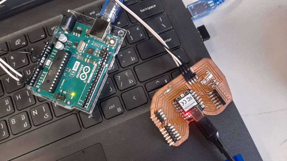
I connected my board and the Arduino Uno R3 using the appropriate pins (SDA to A4, SCL to A5, and a common GND) to set up I2C communication.
Code Implementation
Master (My board)
              #include


                #define SLAVE_ADDRESS 0x08


                void setup() {
                  Wire.begin(); // master mode
                  Serial.begin(115200);
                  delay(1000);
                  Serial.println("I2C Master Ready");
                }


                void loop() {
                  Wire.beginTransmission(SLAVE_ADDRESS);
                  Wire.write("Hello");
                  Wire.endTransmission();
                  Serial.println("Sent: Hello");


                  delay(1000);


                  Wire.requestFrom(SLAVE_ADDRESS, 6);
                  while (Wire.available()) {
                    char c = Wire.read();
                    Serial.print(c);
                  }
                  Serial.println();


                  delay(2000);
                }
Master Code (XIAO RP2040):
The master starts by including the I2C library and sets the slave address to 0x08. Wire.begin() sets up the XIAO RP2040 as the master.
In the loop, it starts a transmission to the slave, sends the word "Hello", and ends the transmission. It also prints that message to the Serial Monitor. Then it waits a second and requests 6 bytes from the slave. If data is available, it reads and prints it one character at a time. A final delay gives time to view results before repeating the loop. The master keeps sending "Hello" and expects "World!" (6 bytes) in return.
Slave (Arduino Uno R3)
              #include


                void setup() {
                  Wire.begin(0x08); // slave mode with address 0x08
                  Wire.onReceive(receiveEvent);
                  Wire.onRequest(requestEvent);
                  Serial.begin(9600);
                  Serial.println("I2C Slave Ready");
                }


                void loop() {
                  delay(100); // passive loop
                }


                void receiveEvent(int howMany) {
                  Serial.print("Received: ");
                  while (Wire.available()) {
                    char c = Wire.read();
                    Serial.print(c);
                  }
                  Serial.println();
                }


                void requestEvent() {
                  Wire.write("World!");
                }
Slave Code (Arduino Uno R3):
The slave uses Wire.begin(0x08) to set its address and listens for communication from the master. Wire.onReceive(receiveEvent) tells it what to do when it gets data. Wire.onRequest(requestEvent) tells it what to do when the master asks for data.
The main loop does nothing since all the work happens in the background. In receiveEvent(), it reads and prints the data sent from the master. In requestEvent(), it replies by sending "World!" (6 bytes), which is what the master asked for. So the slave simply waits, listens, and responds.
Result:
Everything worked as expected!
- The master printed Sent: Hello and received World! from the slave.
- The slave printed Received: Hello when the master sent data.
- The communication was fast, consistent, and reliable across multiple cycles.
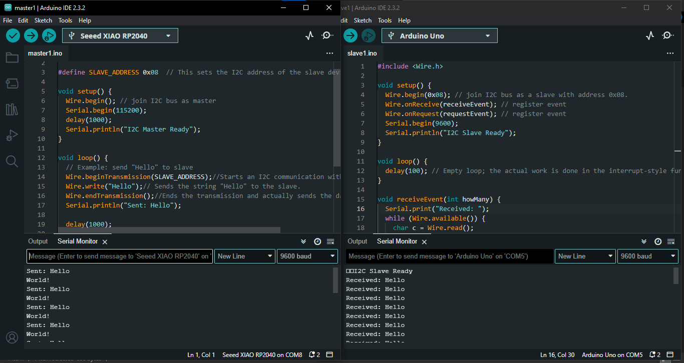
On the left, my XIAO RP2040 board is acting as the master, printing "Sent: Hello" and "World!" in the Serial Monitor. On the right, the Arduino Uno R3 is working as the slave, displaying "Received: Hello" in its Serial Monitor.
View of both boards with I2C communication in action: The XIAO RP2040 (master) and Arduino Uno R3 (slave) successfully exchanging data over I2C.
For a bit of fun, I wanted to try sending an emoji since emojis are commonly used in modern messaging. I updated my code to send a smiling emoji 😂 from the master to the slave, and then had the master request a 6 bytes response from the slave, which I set to be the word "smile!"
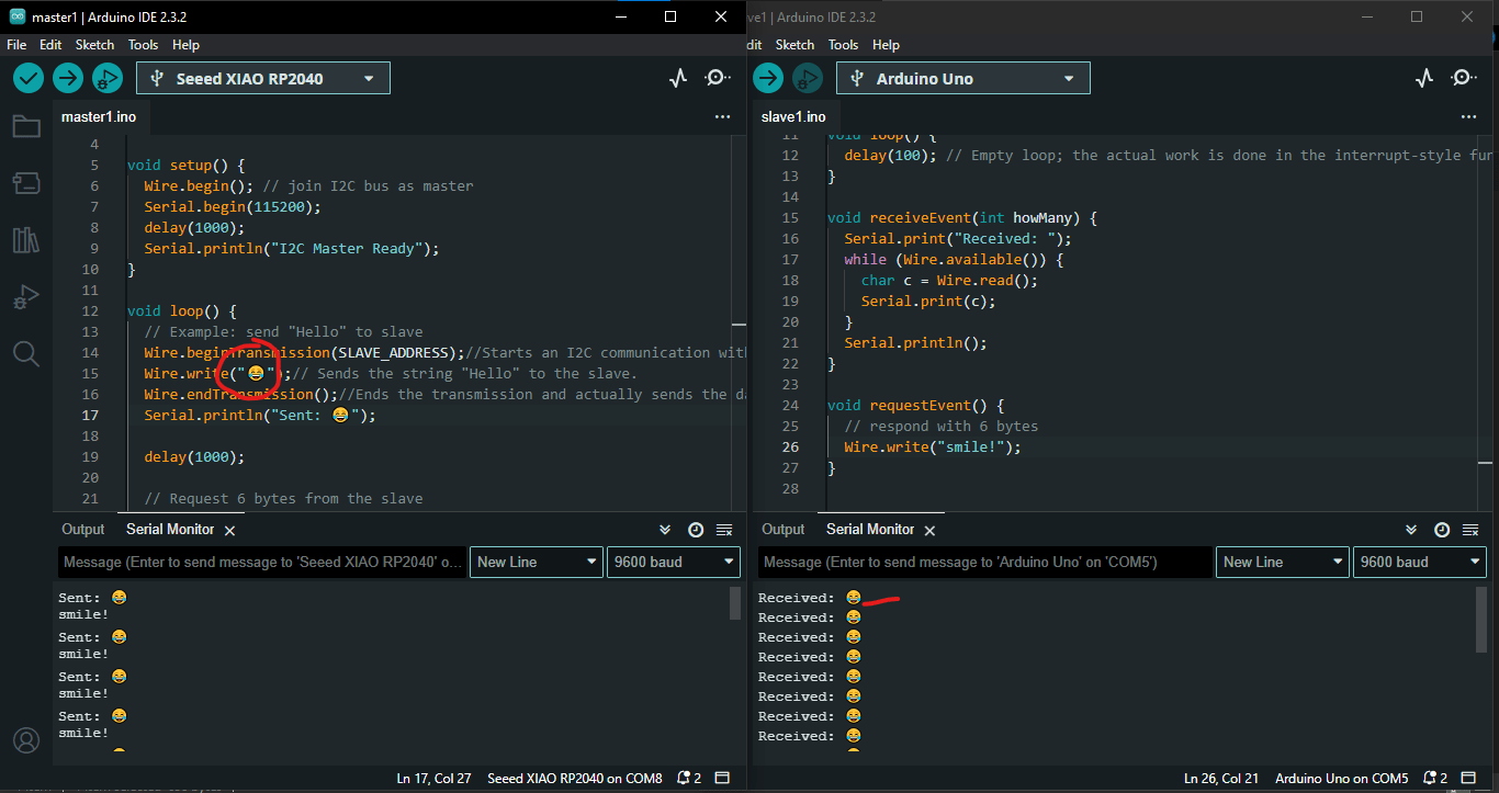
The smiling emoji was successfully sent from the master on the left and received by the Arduino on the right, as shown in the image above.
After diving into I2C communication and successfully sending messages between my XIAO RP2040 (acting as the master) and an Arduino Uno R3 (the slave), I thought, "Why not take this a step further?" This time, I wanted to create a fun real-world interaction. My goal was to control an LED on the slave board using a push button connected to the master. The plan was straightforward: when I pressed the button on the master, the LED on the slave would light up. When I released it, the LED would turn off. It was a perfect way to show how I2C can help not just with message exchanges but also with controlling devices.
Master (My board)
In this setup, the master (my XIAO RP2040) keeps an eye on a push button connected to pin D2. It uses digitalRead to check if the button is pressed. If I press it, the master sends a signal—1 for pressed and 0 for not pressed—to the slave device via I2C. This clever setup lets me control the LED on the slave board from a distance, simply by pressing the button.
              #include

              #define SLAVE_ADDRESS 0x08
#define SWITCH_PIN D2

void setup() {
  Wire.begin(); // master
  Serial.begin(115200);
  pinMode(SWITCH_PIN, INPUT); // button connected to GND
  delay(1000);
  Serial.println("I2C Master Ready");
}

void loop() {
  int switchState = digitalRead(SWITCH_PIN);

  Wire.beginTransmission(SLAVE_ADDRESS);
  if (switchState == LOW) {
    Wire.write("1"); // button pressed
    Serial.println("Sent: 1 (Pressed)");
  } else {
    Wire.write("0"); // button not pressed
    Serial.println("Sent: 0 (Not Pressed)");
  }
  Wire.endTransmission();

  delay(500);
}
Slave (Arduino Uno R3)
On the other end, the slave (my Arduino Uno R3) is always listening for data from the master using the Wire.onReceive() function. When it gets a signal, it reacts by turning the LED connected to pin 13 either on or off. If the slave receives a 1, the LED lights up; if it gets a 0, the LED turns off. This real-time response makes it feel like the devices are truly communicating, creating a seamless interaction based on my button presses.
              #include

#define LED_PIN 13
char receivedChar = '0';

void setup() {
  Wire.begin(0x08); // slave
  Wire.onReceive(receiveEvent);
  Serial.begin(9600);
  pinMode(LED_PIN, OUTPUT);
  Serial.println("I2C Slave Ready");
}

void loop() {
  // update LED state based on receivedChar
  if (receivedChar == '1') {
    digitalWrite(LED_PIN, HIGH);
  } else {
    digitalWrite(LED_PIN, LOW);
  }

  delay(100); // small delay to reduce flickering
}

void receiveEvent(int howMany) {
  while (Wire.available()) {
    receivedChar = Wire.read();
    Serial.print("Received: ");
    Serial.println(receivedChar);
  }
}
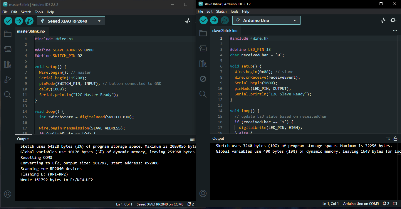
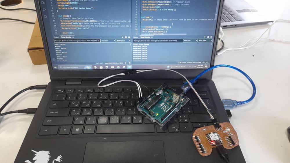
Both codes uploaded to the microcontrollers
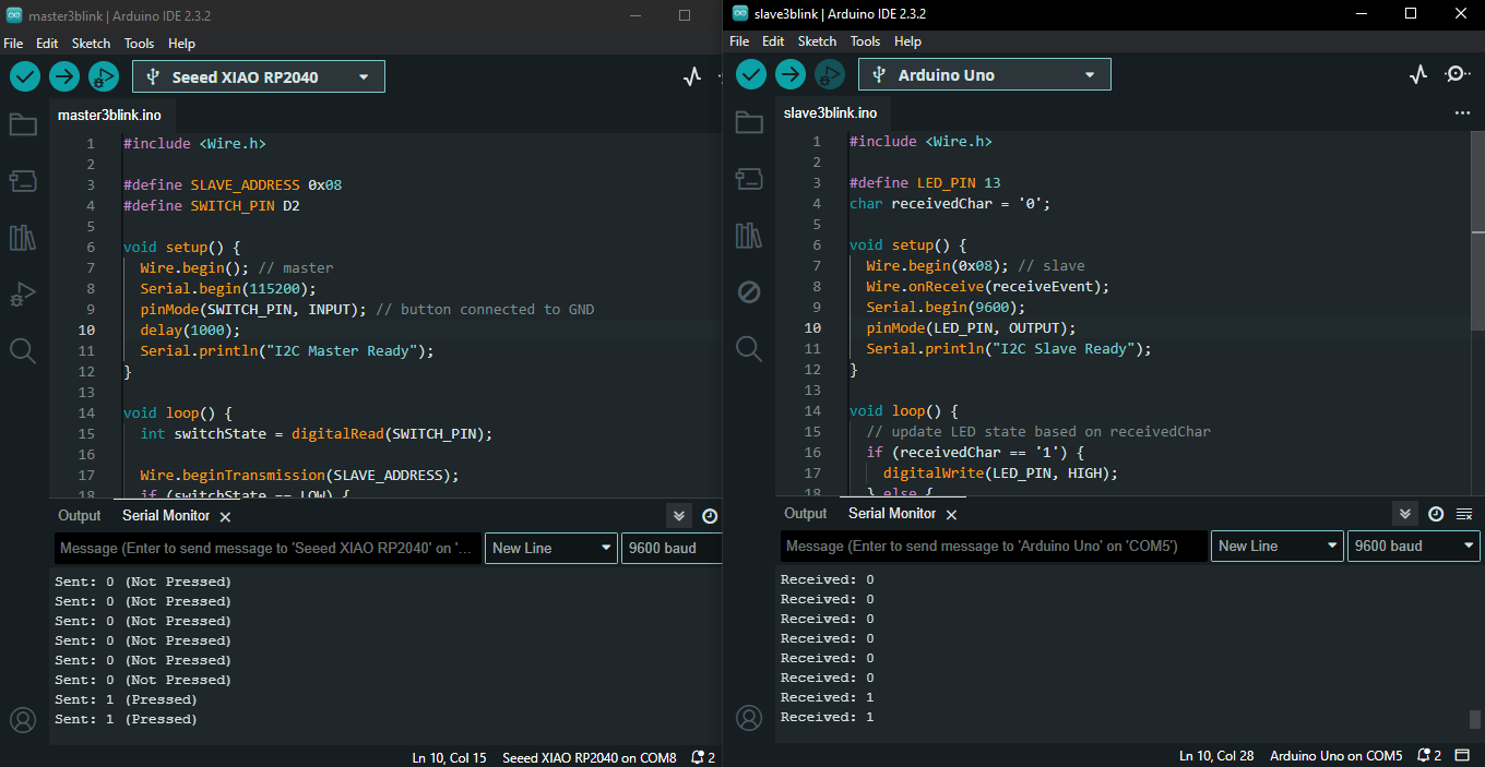
On the left, my XIAO RP2040 board is acting as the master, reading the button state and sending it over I2C. On the right, the Arduino Uno R3 is working as the slave, receiving the signal and controlling the LED on pin 13 based on the received value.
The video shows the XIAO RP2040 master detecting the button press and sending a signal to the Arduino Uno R3 slave. When the button is pressed, the LED connected to pin 13 on the slave board turns ON, and when the button is released, the LED turns OFF — all controlled through I2C communication.
This little project really solidified my grasp of I2C communication. It opened my eyes to its potential for simple remote control tasks. I learned how crucial it is to manage voltage levels, stay consistent with addressing, and handle GPIO inputs and outputs across different boards. Plus, by adding a physical switch and an LED into the mix, I gained a deeper understanding of how to use I2C in interactive embedded systems. It was a rewarding experience that made the technical concepts come to life!
Reflection and Takeaways
This week really expanded my understanding of embedded communication protocols, especially UART and I2C. I discovered just how crucial it is to manage device addresses and byte lengths carefully, along with ensuring solid electrical connections, especially when dealing with boards that run on different voltages. It’s amazing how a small oversight can lead to unexpected results, which taught me the value of paying attention to detail.
One of the most exciting parts was seeing I2C in action by controlling an LED with a push button. It brought the concepts to life and showed me how these protocols can have real-world applications. I also learned that collaboration between different components is key, as compatibility and shared standards play a big role in embedded systems. Engaging with the hardware directly made the theoretical concepts stick, and I’m looking forward to tackling even more complex projects in the future!