For this project, I decided to implement my own communication protocol to send messages between nodes in the network. The protocol was designed to transmit a string containing three key components:
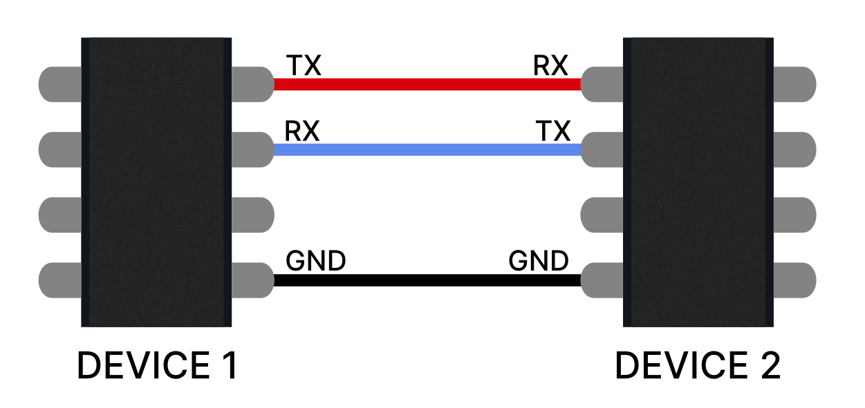
For this UART network, a master and multiple slave configuration was implemented. This setup is necessary to ensure proper communication and coordination between the nodes in the network. In a UART network, where multiple devices are connected, it is crucial to have a central controller (master) to manage communication and prevent data collisions.
The following circuit diagram illustrates the master-slave configuration for the UART network:
- Master Initiates Communication: The master sends a message to a specific slave by including the slave's unique ID in the message.
- Slave Responds: The addressed slave processes the message and sends a response back to the master, if required.
- Communication: When a slave needs to send data to another slave, it first sends the message to the master. The master then checks if the message is addressed to itself or if it should be relayed to all slaves. If the message is intended for another slave, the master forwards it to the addressed slave, which then processes the message and responds accordingly.
#include <Adafruit_NeoPixel.h>

#define LED_PIN     12
#define POWER_PIN   11
#define NUMPIXELS   1

Adafruit_NeoPixel pixels(NUMPIXELS, LED_PIN, NEO_GRB + NEO_KHZ800);

int id = 1;
String message = "";

void setup() {
    Serial.begin(9600);
    Serial1.begin(115200);
    pinMode(POWER_PIN, OUTPUT);
    digitalWrite(POWER_PIN, HIGH);
    pixels.begin();
    pixels.setBrightness(50);
}

void loop() {
    if (Serial.available() > 0) {
    String myInput = Serial.readString();
    myInput = id + ": " + myInput;
    Serial1.println(myInput);
    }

    if (Serial1.available() > 0) {
    String networkIncoming = Serial1.readString();
    int specialCharIndex = networkIncoming.indexOf('@');

    Serial.println(networkIncoming);
    if (specialCharIndex != -1) {
        message = networkIncoming.substring(0, specialCharIndex);
        String destination = networkIncoming.substring(specialCharIndex + 1);
        int receiver = destination.toInt();


        if (receiver == id) {
        int r, g, b;
        //int colon = message.indexOf(';');
        int firstComma = message.indexOf(',');
        int secondComma = message.indexOf(',', firstComma + 1);

            Serial.println("message= " + message + ", receiver=" + String(receiver));

        if (firstComma != -1 && secondComma != -1) {
            r = message.substring(0, firstComma).toInt();
            Serial.println(r);
            g = message.substring(firstComma + 1, secondComma).toInt();
            b = message.substring(secondComma + 1).toInt();
            setColor(r, g, b);
        }
        }else{
        Serial.println("Relaying message...");
        Serial1.println(networkIncoming);
        //Serial.println("Not my message...");
        }
        message = "";
    }
    }
}

void setColor(int r, int g, int b) {
    pixels.setPixelColor(0, pixels.Color(r, g, b));
    pixels.show();
}
Advantages of the Custom Protocol
- Simple and easy to implement.
- Customizable to meet specific project requirements.
- Provides a clear structure for message transmission and routing.
Challenges and Considerations
- Ensuring reliable message delivery in the presence of noise or interference.
- Handling cases where multiple nodes attempt to send messages simultaneously.
- Optimizing the protocol for speed and efficiency in larger networks.
Second Iteration of the Protocol
After observing delays in node responses and the need for a more robust protocol to handle additional sensors, we implemented a new protocol structure. The updated protocol is designed to be faster and more flexible, allowing nodes to process commands efficiently and implement custom responses. The new protocol format is as follows:
<COMMAND>:<DATA>@<TO_ID>#<FROM_ID>;
Each component of the protocol serves a specific purpose:
- COMMAND: Specifies the action or operation to be performed (e.g., "SET", "GET", "PING").
- DATA: Contains the data or parameters associated with the command.
- TO_ID: The unique identifier of the recipient node.
- FROM_ID: The unique identifier of the sender node.
- ; Marks the end of the message.
For example, a message to set the color of a node with ID 02 to red (255,0,0) from node 01 would look like this:
COLOR:255,0,0@02#01;
Advantages of the New Protocol
- Faster processing due to a simplified and structured format.
- Supports custom commands for enhanced flexibility.
- Clear separation of components for easier parsing and debugging.
Implementation
The updated protocol was implemented in the nodes' firmware. Below is the updated code:
#include <Adafruit_NeoPixel.h>

    #define LED_PIN     12
    #define POWER_PIN   11
    #define NUMPIXELS   1

    Adafruit_NeoPixel pixels(NUMPIXELS, LED_PIN, NEO_GRB + NEO_KHZ800);

    int id = 1;
    String message = "";

    void setup() {
        Serial.begin(9600);
        Serial1.begin(115200);
        pinMode(POWER_PIN, OUTPUT);
        digitalWrite(POWER_PIN, HIGH);
        pixels.begin();
        pixels.setBrightness(50);
    }

    void loop() {
        // Forward user input with FROM_ID tagging
        if (Serial.available() > 0) {
        String myInput = Serial.readStringUntil('\n');
        myInput.trim();

        if (myInput.indexOf("@")<0 || myInput.indexOf("#") < 0) {
            myInput += "@0#" + String(id); // Add receiver=0 (broadcast) and sender
        }
        myInput += ";"; // Ensure the message ends correctly
        Serial1.println(myInput);

        }

        // Receive network message
        if (Serial1.available() > 0) {
        String incoming = Serial1.readStringUntil(';'); // Read until semicolon
        incoming.trim();

        Serial.println("Raw: " + incoming);

        // Extract command
        int colonIndex = incoming.indexOf(':');
        int atIndex = incoming.indexOf('@');
        int hashIndex = incoming.indexOf('#');

        if (colonIndex == -1 || atIndex == -1 || hashIndex == -1) return;

        String command = incoming.substring(0, colonIndex);
        String data = incoming.substring(colonIndex + 1, atIndex);
        int toID = incoming.substring(atIndex + 1, hashIndex).toInt();
        int fromID = incoming.substring(hashIndex + 1).toInt();

        Serial.println("Command: " + command);
        Serial.println("Data: " + data);
        Serial.println("To ID: " + String(toID));
        Serial.println("From ID: " + String(fromID));

        if (toID == id || toID == 0) {
            dispatchCommand(command, data);
        } else {
            Serial.println("Not my message...");
        }
        }
    }

    void dispatchCommand(String command, String data) {
        if (command == "COLOR") {
        int firstComma = data.indexOf(',');
        int secondComma = data.indexOf(',', firstComma + 1);

        if (firstComma == -1 || secondComma == -1) return;

        int r = data.substring(0, firstComma).toInt();
        int g = data.substring(firstComma + 1, secondComma).toInt();
        int b = data.substring(secondComma + 1).toInt();

        Serial.println("Setting color to R:" + String(r) + " G:" + String(g) + " B:" + String(b));
        setColor(r, g, b);
        }

        // Add more commands like BUZZ, MOVE, etc. here:
        else {
        Serial.println("Unknown command: " + command);
        }
    }

    void setColor(int r, int g, int b) {
        pixels.setPixelColor(0, pixels.Color(r, g, b));
        pixels.show();
    }
This updated implementation ensures faster response times and allows nodes to handle custom commands effectively. The protocol's flexibility also makes it easier to expand the network with additional features in the future.
The code above is the same for all slaves, for the master it needed one modification to allow the mater to redirect incoming data to other slaves if a slave is attempting to communicate with a slave.
if (toID == id || toID == 0) {
    dispatchCommand(command, data);
    } else {
    Serial.println("Relaying message...");
    Serial1.println(incoming + ";"); // reappend delimiter

    //Serial.println("Not my message...");
}
In this case, the master will relay the message to the slave with the ID specified in the message. The master will also add a semicolon at the end of the message to ensure that the slave can read it correctly.
Controlling nodes in the network
After this step the slaves and mater can implemet their own commands to respond to.
Implementing Commands for Master and Slaves
After the main protocol was implemented, the master and slaves were programmed to listen for specific commands and act upon them. This allowed each node to perform unique tasks based on the received instructions. In this system, the master node was equipped with an RFID scanner, while node 3 had an LCD display attached to it. The goal was to automatically send scanned RFID information from the master to node 3 for display.
Master Node Implementation
The master node was programmed to read data from the RFID scanner and send it to node 3 using the custom protocol. The RFID data was formatted as a message and transmitted with the appropriate recipient ID.
/*
* ---------------------------------------
* ---------------------------------------
*             MFRC522      Seeed Studio
*             Reader/PCD   Xiao-RP2040
* Signal      Pin          Pin
* ---------------------------------------
* RST/Reset   RST          D1
* SPI SS      SDA(SS)      D2
* SPI MOSI    MOSI         D10 / MOSI
* SPI MISO    MISO         D9 / MISO
* SPI SCK     SCK          D8 / SCK
*
*
*/

#include <SPI.h>
#include <MFRC522.h>

#define SS_PIN D2
#define RST_PIN D1


#include <Adafruit_NeoPixel.h>

#define LED_PIN     12
#define POWER_PIN   11
#define NUMPIXELS   1

const int vibrator = D0;

Adafruit_NeoPixel pixels(NUMPIXELS, LED_PIN, NEO_GRB + NEO_KHZ800);

int id = 1;
String message = "";

// --- Motor Control State ---
unsigned long motorStartTime = 0;
unsigned long lastToggleTime = 0;
unsigned long motorDuration = 0;
unsigned long toggleInterval = 0;
bool motorRunning = false;
bool motorState = false;
int motorPin = 0;


MFRC522 rfid(SS_PIN, RST_PIN); // Instance of the class

// Init array that will store new NUID
byte nuidPICC[4];

void setup() {
    pinMode(vibrator, OUTPUT);

    SPI.begin(); // Init SPI bus
    rfid.PCD_Init(); // Init MFRC522

    Serial.begin(9600);
    Serial1.begin(115200);
    pinMode(POWER_PIN, OUTPUT);
    digitalWrite(POWER_PIN, HIGH);
    pixels.begin();
    pixels.setBrightness(50);

    digitalWrite(vibrator, HIGH);
    delay(1000);
    digitalWrite(vibrator, LOW);
    delay(500);
    digitalWrite(vibrator, HIGH);
    delay(1000);
    digitalWrite(vibrator, LOW);
    delay(1000);
    digitalWrite(vibrator, HIGH);
}

void loop() {
    updateMotorPulse();
    // Forward user input with FROM_ID tagging
    if (Serial.available() > 0) {
    String myInput = Serial.readStringUntil('\n');
    myInput.trim();

    myInput += (String)"#"+id+(String)";"; // Ensure the message ends correctly
    Serial1.println(myInput);

    }

    if(rfid.PICC_IsNewCardPresent()){ // if there is new card
    if(rfid.PICC_ReadCardSerial()){

        Serial.print(F("PICC type: "));
        MFRC522::PICC_Type piccType = rfid.PICC_GetType(rfid.uid.sak);
        Serial.println(rfid.PICC_GetTypeName(piccType));

        // Check is the PICC of Classic MIFARE type
        if (piccType != MFRC522::PICC_TYPE_MIFARE_MINI &&
        piccType != MFRC522::PICC_TYPE_MIFARE_1K &&
        piccType != MFRC522::PICC_TYPE_MIFARE_4K) {
        Serial.println(F("Your tag is not of type MIFARE Classic."));
        return;
        }


        if (rfid.uid.uidByte[0] != nuidPICC[0] ||
        rfid.uid.uidByte[1] != nuidPICC[1] ||
        rfid.uid.uidByte[2] != nuidPICC[2] ||
        rfid.uid.uidByte[3] != nuidPICC[3] ) {
        Serial.println(F("A new card has been detected."));

        // Store NUID into nuidPICC array
        for (byte i = 0; i < 4; i++) {
        nuidPICC[i] = rfid.uid.uidByte[i];
        }

        String dat = decToString(rfid.uid.uidByte, rfid.uid.size);
        dat = "DISPLAY:"+dat+"@3#1";
        Serial1.println(dat);
        Serial.println(dat);

        Serial.println(F("The NUID tag is:"));
        Serial.print(F("In hex: "));
        printHex(rfid.uid.uidByte, rfid.uid.size);
        Serial.println();
        Serial.print(F("In dec: "));
        printDec(rfid.uid.uidByte, rfid.uid.size);
        Serial.println();
    }
    else Serial.println(F("Card read previously."));

    // Halt PICC
    rfid.PICC_HaltA();

    // Stop encryption on PCD
    rfid.PCD_StopCrypto1();

    }
    }

    // Receive network message
    if (Serial1.available() > 0) {
    String incoming = Serial1.readStringUntil(';'); // Read until semicolon
    incoming.trim();

    Serial.println("Raw: " + incoming);

    // Extract command
    int colonIndex = incoming.indexOf(':');
    int atIndex = incoming.indexOf('@');
    int hashIndex = incoming.indexOf('#');

    if (colonIndex == -1 || atIndex == -1 || hashIndex == -1) return;

    String command = incoming.substring(0, colonIndex);
    String data = incoming.substring(colonIndex + 1, atIndex);
    int toID = incoming.substring(atIndex + 1, hashIndex).toInt();
    int fromID = incoming.substring(hashIndex + 1).toInt();

    Serial.println("Command: " + command);
    Serial.println("Data: " + data);
    Serial.println("To ID: " + String(toID));
    Serial.println("From ID: " + String(fromID));

    if (toID == id || toID == 0) {
        dispatchCommand(command, data);
    } else {
        Serial.println("Relaying message...");
        Serial1.println(incoming + ";"); // reappend delimiter

        //Serial.println("Not my message...");
    }
    }
}

void dispatchCommand(String command, String data) {
    if (command == "COLOR") {
    int firstComma = data.indexOf(',');
    int secondComma = data.indexOf(',', firstComma + 1);

    if (firstComma == -1 || secondComma == -1) return;

    int r = data.substring(0, firstComma).toInt();
    int g = data.substring(firstComma + 1, secondComma).toInt();
    int b = data.substring(secondComma + 1).toInt();

    Serial.println("Setting color to R:" + String(r) + " G:" + String(g) + " B:" + String(b));
    setColor(r, g, b);
    }

    if(command == "VIBRATE"){

    int firstComma = data.indexOf(',');
    if(firstComma == -1) return;

    int duration = data.substring(0, firstComma).toInt();
    int freq = data.substring(firstComma + 1).toInt();

    startMotorPulse(vibrator, freq, duration); // Motor on pin 9, 5Hz for 3s
    }
    // Add more commands like BUZZ, MOVE, etc. here:

    else {
    Serial.println("Unknown command: " + command);
    }
}


void setColor(int r, int g, int b) {
    pixels.setPixelColor(0, pixels.Color(r, g, b));
    pixels.show();
}


void startMotorPulse(int pin, float frequency, unsigned long durationMs) {
    motorPin = pin;
    pinMode(motorPin, OUTPUT);

    toggleInterval = 1000.0 / (frequency * 2); // Half-period in ms
    motorDuration = durationMs;
    motorStartTime = millis();
    lastToggleTime = 0;
    motorRunning = true;
    motorState = false; // Start OFF
    digitalWrite(motorPin, HIGH);
}

// Call this repeatedly inside loop()
void updateMotorPulse() {
    if (!motorRunning) return;

    unsigned long currentTime = millis();

    // Check if it's time to toggle
    if (currentTime - lastToggleTime >= toggleInterval) {
    motorState = !motorState;
    digitalWrite(motorPin, motorState);
    lastToggleTime = currentTime;
    }

    // Check if duration expired
    if (currentTime - motorStartTime >= motorDuration) {
    digitalWrite(motorPin, HIGH); // Ensure motor is off
    motorRunning = false;
    }
}

/**
* Helper routine to dump a byte array as hex values to Serial.
*/
void printHex(byte *buffer, byte bufferSize) {
    for (byte i = 0; i < bufferSize; i++) {
    Serial.print(buffer[i] < 0x10 ? " 0" : " ");
    Serial.print(buffer[i], HEX);
    }
}

// TO STRING
String decToString(byte *buffer, byte bufferSizer){
    String dat = "";
    for(byte i = 0; i < bufferSizer; i++){
    dat += " "+String((char)buffer[i], DEC);
    }

    return dat;
}

/**
* Helper routine to dump a byte array as dec values to Serial.
*/
void printDec(byte *buffer, byte bufferSize) {
    for (byte i = 0; i < bufferSize; i++) {
    Serial.print(' ');
    Serial.print(buffer[i], DEC);
    }
}
Node 3 Implementation
Node 3 was programmed to listen for the DISPLAY command. When it received a message with this command, it extracted the data (RFID UID) and displayed it on the attached LCD screen.
if(command == "DISPLAY") {
    lcd.clear();
    lcd.setCursor(0, 0);
    lcd.print("UID: ");
    lcd.print(data);
}
System Workflow
- The master node reads the RFID UID when a card is scanned.
- The master formats the UID into a message using the custom protocol and sends it to node 3.
- Node 3 receives the message, extracts the UID, and displays it on the LCD screen.
This implementation demonstrates how the custom protocol enables seamless communication and task delegation between nodes in the network.