For this week's group assignment, we probed an input device's analog levels and digital signals. This involved using tools such as oscilloscopes and multimeters to analyze the behavior of input devices and understand their signal characteristics. Our findings were documented on the group work page, and I reflected on what I learned on my individual page.
For the individual assignment, I measured something by adding a sensor to a microcontroller board that I had designed. This process involved integrating the sensor, writing code to read its data, and testing the setup to ensure accurate measurements. It allowed me to apply the knowledge gained from the group assignment and further develop my skills in sensor integration and microcontroller programming.
Group Assignment
For the group assignment, we probed an input device's analog levels and digital signals. This involved using tools such as oscilloscopes and multimeters to analyze the behavior of input devices and understand their signal characteristics. Our findings were documented on the group work page, and I reflected on what I learned on my individual page.
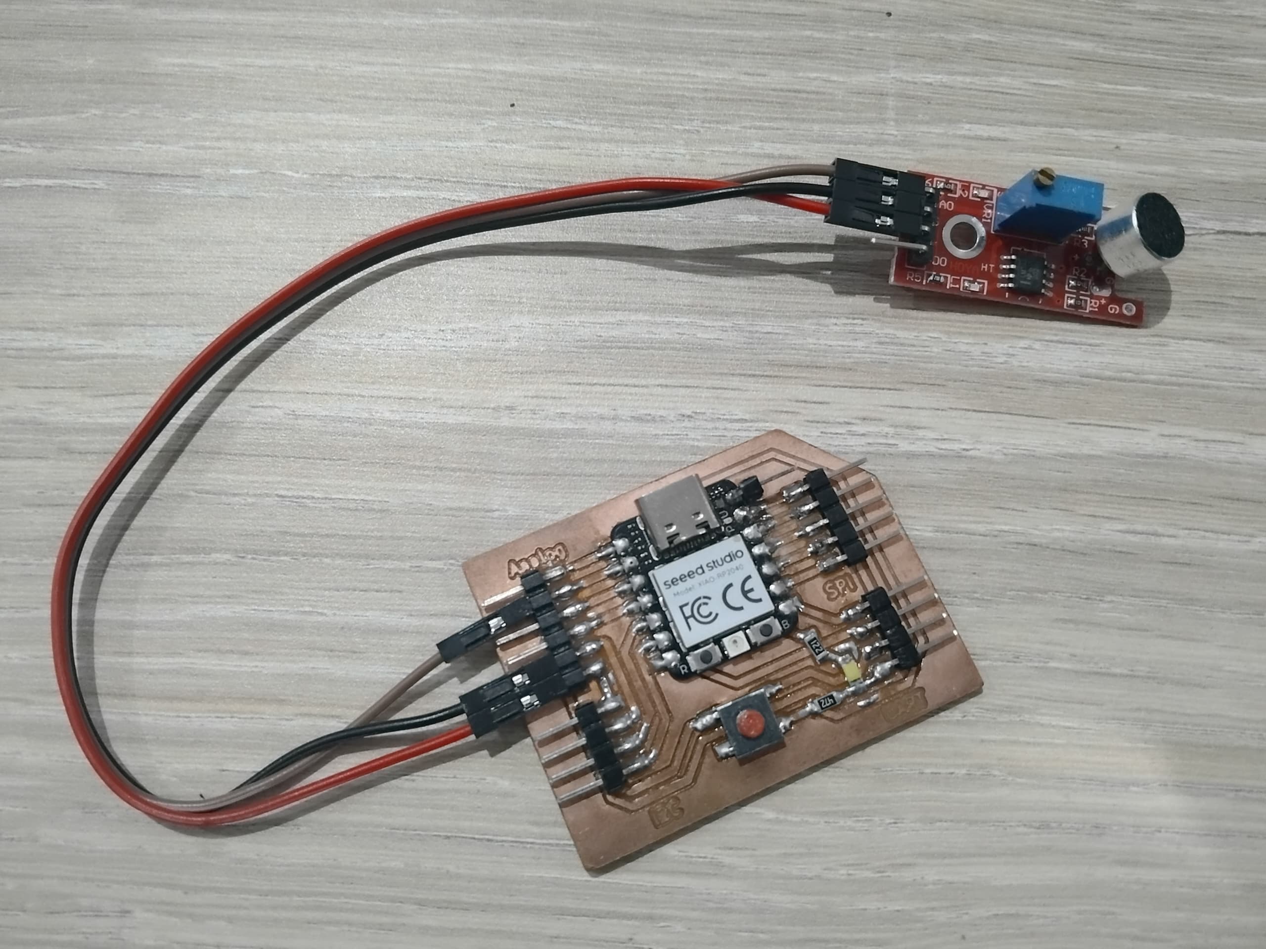
For the individual assignment, I used the development board I designed during Week 06 - Electronics Design. To fulfill the task of "Measure something: add a sensor to a microcontroller board that you have designed and read it," I chose to measure a microphone module. The microphone module was integrated with my development board to capture and analyze sound signals.
This process involved connecting the microphone module to the appropriate pins on the board, writing code to read the analog signals from the microphone, and processing the data to observe sound levels. By using my development board, I was able to test the microphone module's functionality and ensure accurate readings. This assignment allowed me to deepen my understanding of sensor integration and signal processing while utilizing the board I had previously designed.
Understanding Input Devices
Input devices are components or peripherals that allow a system, such as a microcontroller or computer, to receive data from the external environment. These devices play a crucial role in enabling interaction between the physical world and digital systems by converting physical signals into data that can be processed.
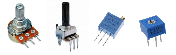
Analog Input Devices: These devices provide continuous signals that vary over time. Examples include sensors like temperature sensors, microphones, and light-dependent resistors (LDRs). Analog input devices typically output a range of values, which are often converted to digital signals using an Analog-to-Digital Converter (ADC) for processing.
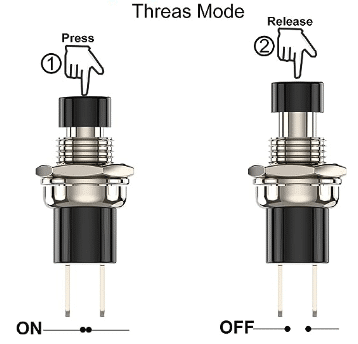
Digital Input Devices: These devices provide discrete signals, typically in the form of binary values (0 or 1). Examples include push buttons, digital switches, and infrared sensors. Digital input devices are straightforward to interface with microcontrollers as they do not require conversion and can be directly read as HIGH or LOW states.
In summary, input devices are essential for capturing data from the environment. Analog input devices provide continuous signals and require conversion for processing, while digital input devices provide discrete signals that are easier to interface with digital systems.
Microphone Module
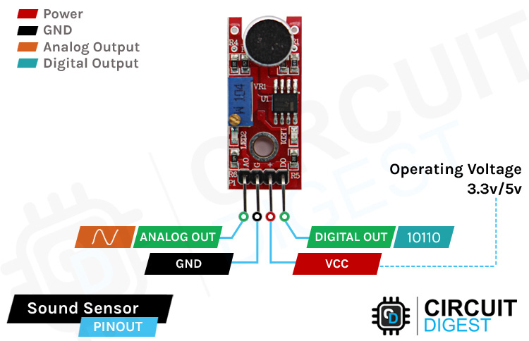
The microphone module is a type of input device that captures sound waves and converts them into electrical signals. It is commonly used in various applications, including audio recording, voice recognition, and sound level measurement. The microphone module typically consists of a microphone element, an amplifier circuit, and output pins for connecting to a microcontroller or other devices.
In this project, I used a microphone module to measure sound levels. The module outputs an analog voltage signal that corresponds to the sound intensity. By connecting the microphone module to my development board, I was able to read the analog signal and process it using the microcontroller's ADC.
The microphone module typically has three pins: VCC (power supply), GND (ground), and OUT (output). The VCC pin is connected to the power supply, the GND pin is connected to ground, and the OUT pin is connected to an analog input pin on the microcontroller. The output voltage from the microphone module varies based on the sound intensity, allowing for sound level measurement.
To read the microphone module's output, I wrote a simple program that continuously samples the analog signal from the OUT pin. The program converts the analog voltage to a digital value using the microcontroller's ADC and displays the sound level on a serial monitor. This setup allowed me to observe real-time sound levels and analyze the microphone module's performance.
Overall, the microphone module is a versatile input device that enables sound measurement and analysis. By integrating it with my development board, I was able to explore its functionality and gain insights into sound signal processing.
Code
Here is the code I used to read the microphone module's output and display the sound level on a serial monitor:
int micPin = D1;           // Analog pin connected to the microphone module
int micValue = 0;          // Variable to store the microphone value
void setup() {
  pinMode(micPin, INPUT);
  Serial.begin(9600);      // Initialize serial communication at 9600 baud rate
}
void loop() {
  micValue = analogRead(micPin);        // Read the analog value from the microphone module
  Serial.print("Microphone Value: ");
  Serial.println(micValue);             // Print the microphone value to the serial monitor
  delay(500);                           // Delay for half a second for smoother output
}
This code initializes the serial communication, reads the analog value from the microphone module, and prints it to the serial monitor. The delay allows for a smoother output.
By running this code on my development board, I was able to observe the microphone module's output in real-time and analyze the sound levels captured by the module.
Demonstration
Here is a video demonstrating the microphone module in action, capturing sound levels and displaying the output:
This video showcases the setup and functionality of the microphone module, providing a visual representation of its performance.
RFID Scanner
The RFID scanner is a digital input device that uses radio frequency identification technology to read data stored on RFID tags. It is commonly used in access control systems, inventory management, and other applications requiring wireless identification.
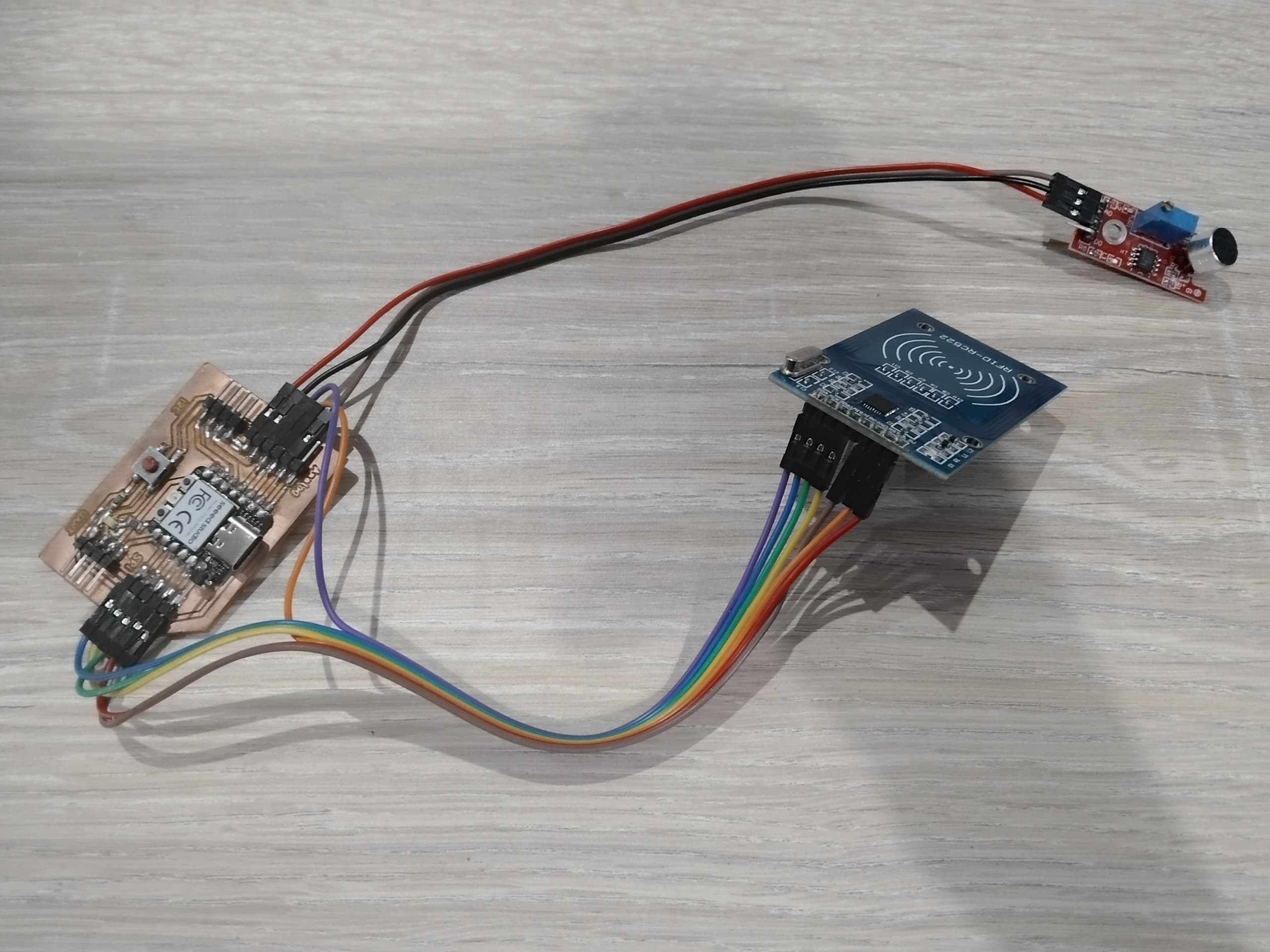
In this project, I integrated an RFID scanner with my development board to read RFID tags. The scanner communicates with the microcontroller using the SPI (Serial Peripheral Interface) protocol, which is a synchronous serial communication interface commonly used for short-distance communication between microcontrollers and peripherals.
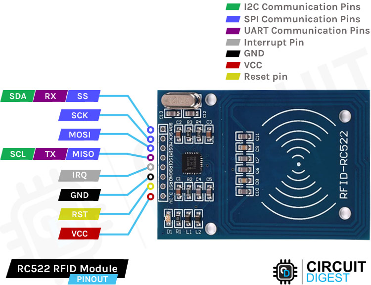
The SPI interface typically consists of four main lines: SCK (Serial Clock), MOSI (Master Out Slave In), MISO (Master In Slave Out), and SS (Slave Select). The RFID scanner's pins include VCC (power supply), GND (ground), SCK, MOSI, MISO, and SS, which are connected to the corresponding SPI pins on the microcontroller for communication.
To read data from the RFID scanner, I wrote a program that initializes the SPI interface and communicates with the scanner to retrieve the tag's unique identifier. When an RFID tag is scanned, the scanner sends the tag's data over the SPI interface to the microcontroller, which processes and displays the data on the serial monitor.
Here is the code I used to interface with the RFID scanner:
#include <SPI.h>
#include <MFRC522.h>

// RFID setup
#define RST_PIN D3
#define SS_PIN D2
MFRC522 rfid(SS_PIN, RST_PIN);

// Microphone setup
int micPin = D1; // Analog pin connected to the microphone module
int micValue = 0;

void setup() {

  pinMode(micPin, INPUT);

  // Initialize RFID
  SPI.begin();
  rfid.PCD_Init();

  // Initialize Serial
  Serial.begin(9600);
}

void loop() {
  // Read microphone value
  micValue = analogRead(micPin);


  Serial.print("Mic Value:");
  Serial.println(micValue);
  delay(500);

  // Check for RFID card
  if (rfid.PICC_IsNewCardPresent() && rfid.PICC_ReadCardSerial()) {


  Serial.print("RFID UID:");

  // Print UID to LCD
  for (byte i = 0; i < rfid.uid.size; i++) {
    Serial.print(rfid.uid.uidByte[i] < 0x10 ? "0" : "");
    Serial.print(rfid.uid.uidByte[i], HEX);
    if (i != rfid.uid.size - 1) Serial.print(":");
  }
  Serial.println();
  delay(3000);

  // Halt RFID card
  rfid.PICC_HaltA();
  }
}
This code initializes the RFID scanner, reads the tag data, and displays it on the serial monitor. The program processes the tag's unique identifier and resets the buffer after each scan.
By integrating the RFID scanner with my development board, I was able to explore its functionality and demonstrate its use in reading RFID tags for identification purposes.
Demo Video
Below is a demonstration video showcasing both the microphone module and RFID scanner outputting data on the serial monitor:
This video highlights the real-time data captured by the microphone module and RFID scanner, demonstrating their functionality and integration with the development board.
Conclusion
In this week's assignment, I explored the integration and functionality of input devices, including the microphone module and RFID scanner. By connecting these devices to my development board, I was able to measure sound levels and read RFID tags, gaining valuable insights into sensor integration and signal processing.
The microphone module allowed me to capture analog sound signals and process them using the microcontroller's ADC, while the RFID scanner demonstrated the ability to read digital data from RFID tags. These experiments provided a deeper understanding of how input devices interact with microcontrollers and how they can be used in various applications.
You can find the Arduino code used for this project at the following links: