Tested runout, alignment, fixturing, speeds, feeds, materials, and toolpaths for our machine.
Documented our work on the group work page and reflected on what we learned on our individual pages.
Individual Project
Designed, milled, and assembled something big (meter scales of size).
Group Assignment
Note: This week, cutting and assembly were not possible because the CNC machines were unoperable. As a result, the group assignment was put on halt. Updates will follow as soon as the machines are available.
For more details and group documentation, visit the Group Assignment Page.
Individual Assignment
For the individual assignment, I designed a table using SolidWorks, a powerful 3D CAD software. I started by sketching the table components—such as the tabletop and legs—in SolidWorks, carefully defining their dimensions and features. After creating the individual parts, I assembled them virtually to ensure proper fit and stability. Once the design was complete, I exported the parts as DXF files suitable for CNC cutting. These files were then used to generate toolpaths for the CNC machine, allowing me to fabricate the table components from sheet material. Finally, I assembled the cut pieces to complete the table, verifying that the design translated accurately from the digital model to the physical product.
Below is a step-by-step guide of how I designed my table in SolidWorks, exported the DXF files, and created the toolpaths for CNC cutting:
Initial Concept & Sketching:
Defined the table dimensions and basic design requirements (height, width, length, leg style, joinery type).
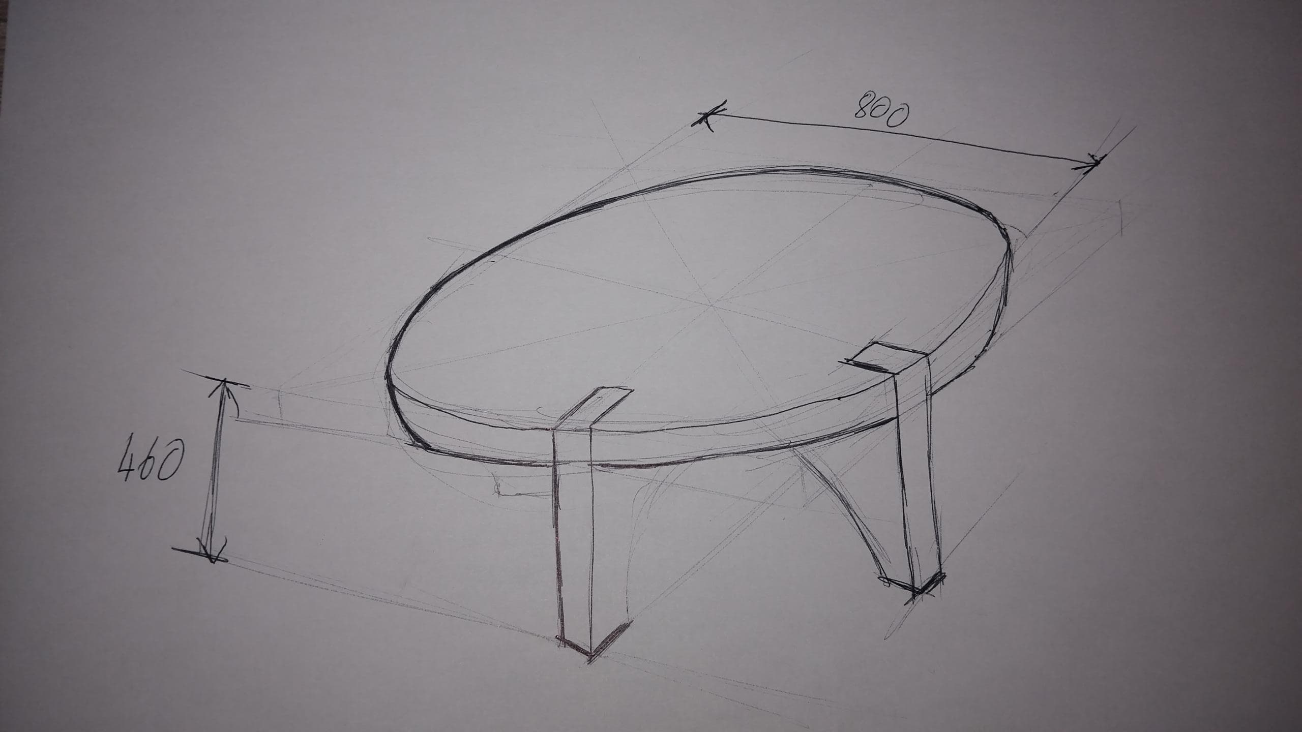
Sketched a rough layout of the tabletop and legs on paper to visualize the assembly.
Sketch Example:
Figure: Hand-drawn sketch of the table concept showing dimensions and basic structure.
Part Design in SolidWorks:
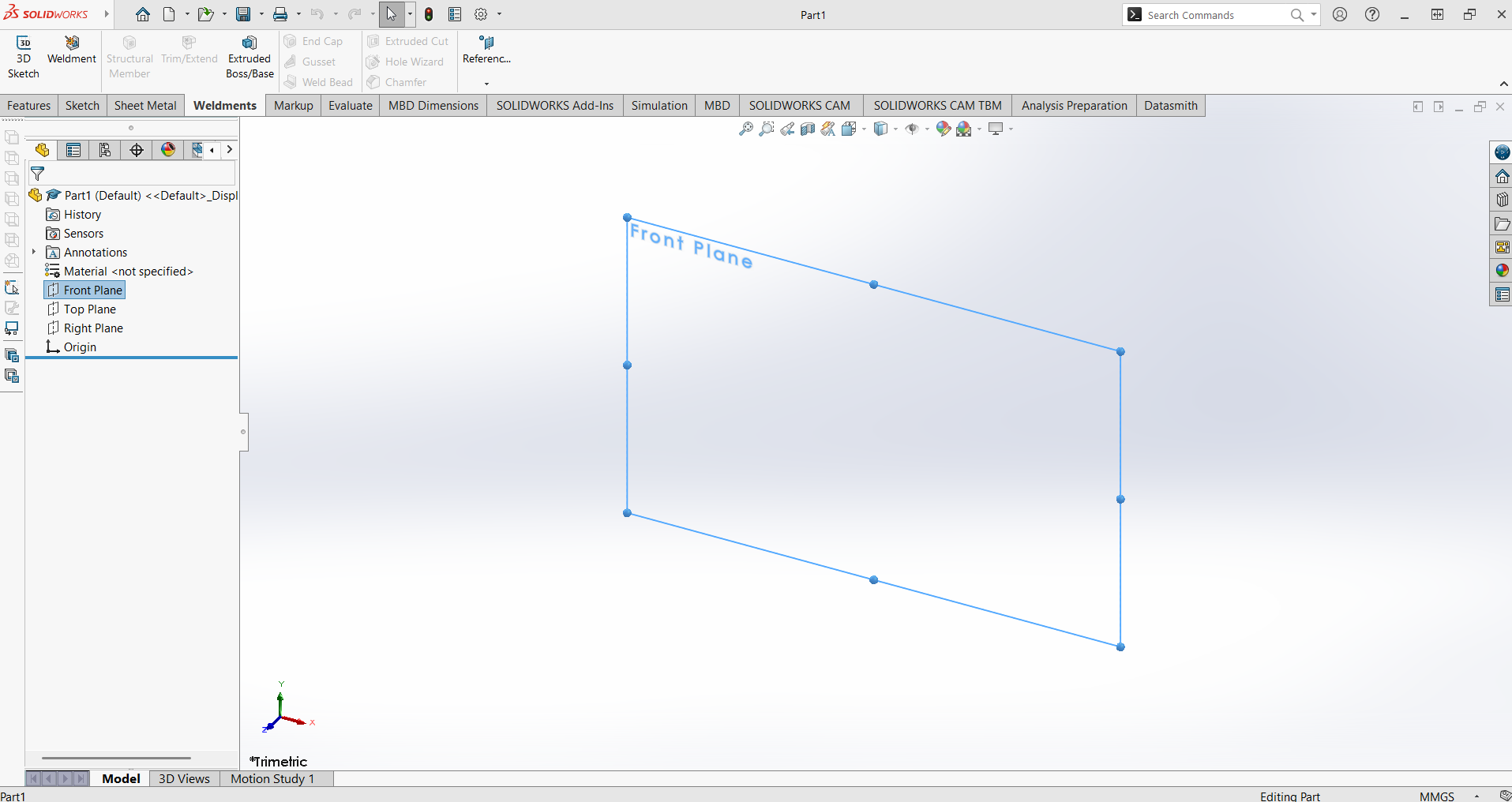
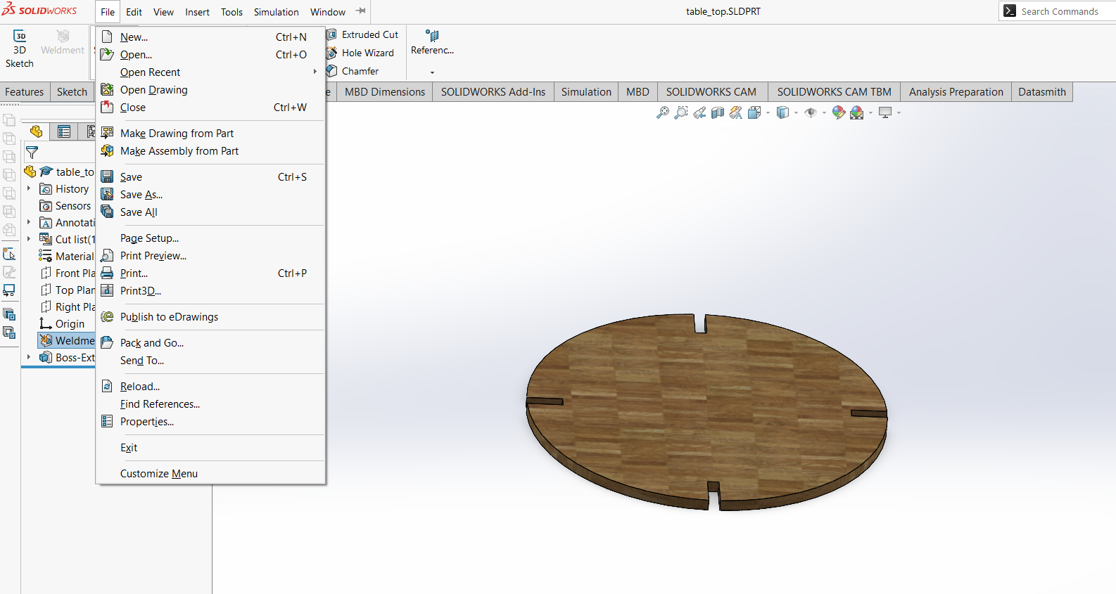
Opened SolidWorks and created a new part file for each table component (tabletop, feet).
Top Part
Foot 1
Foot 2
Figure: Creating new part files for the tabletop and feet in SolidWorks.
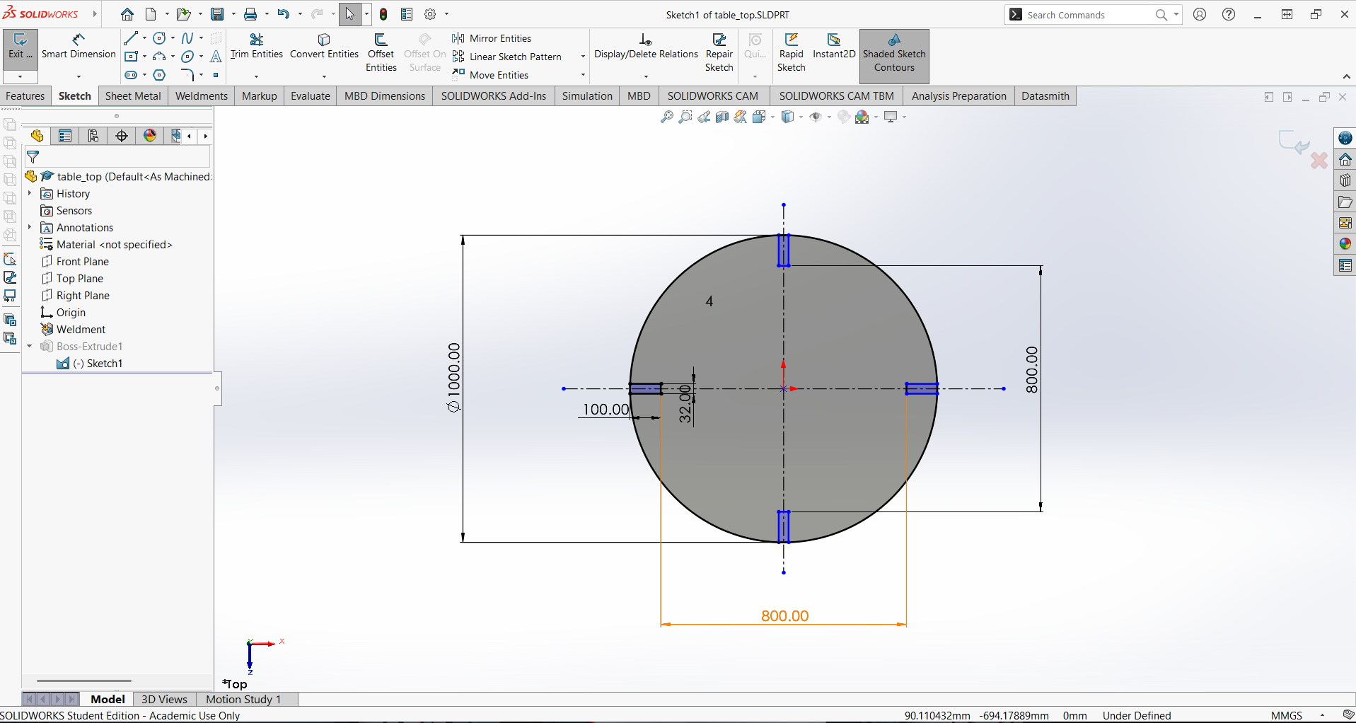
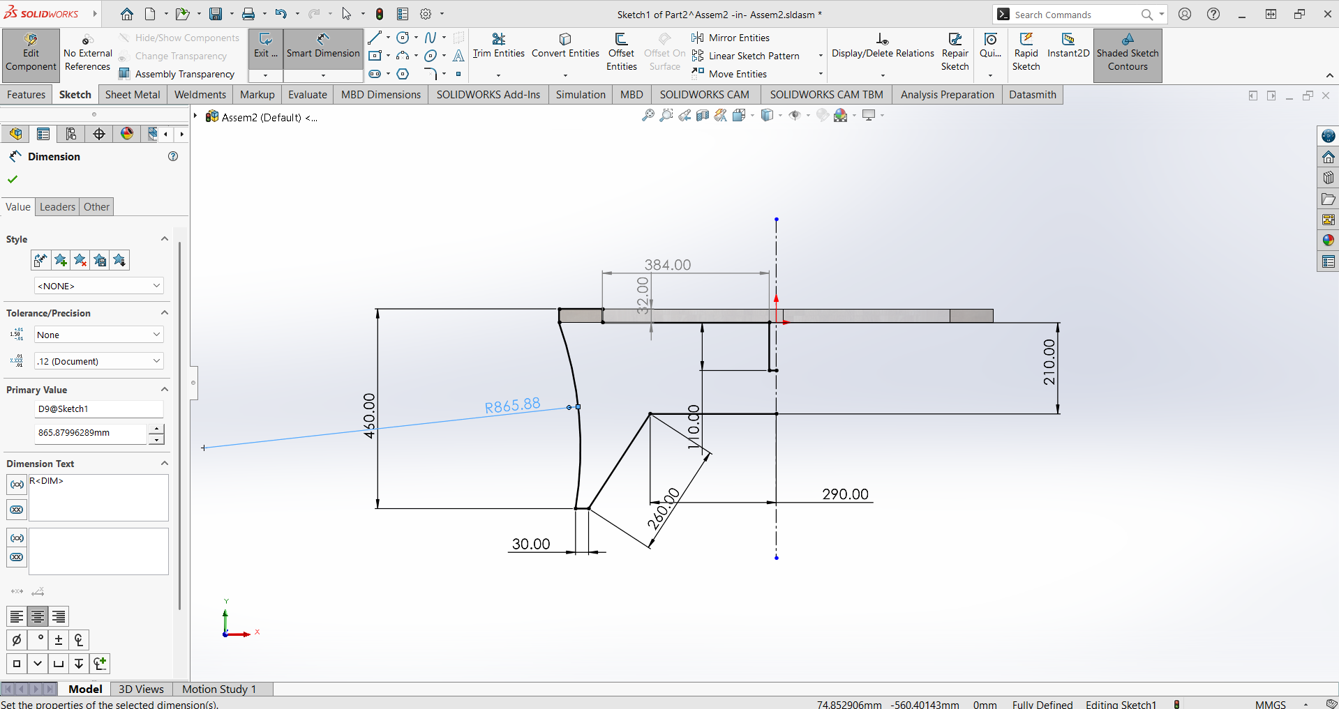
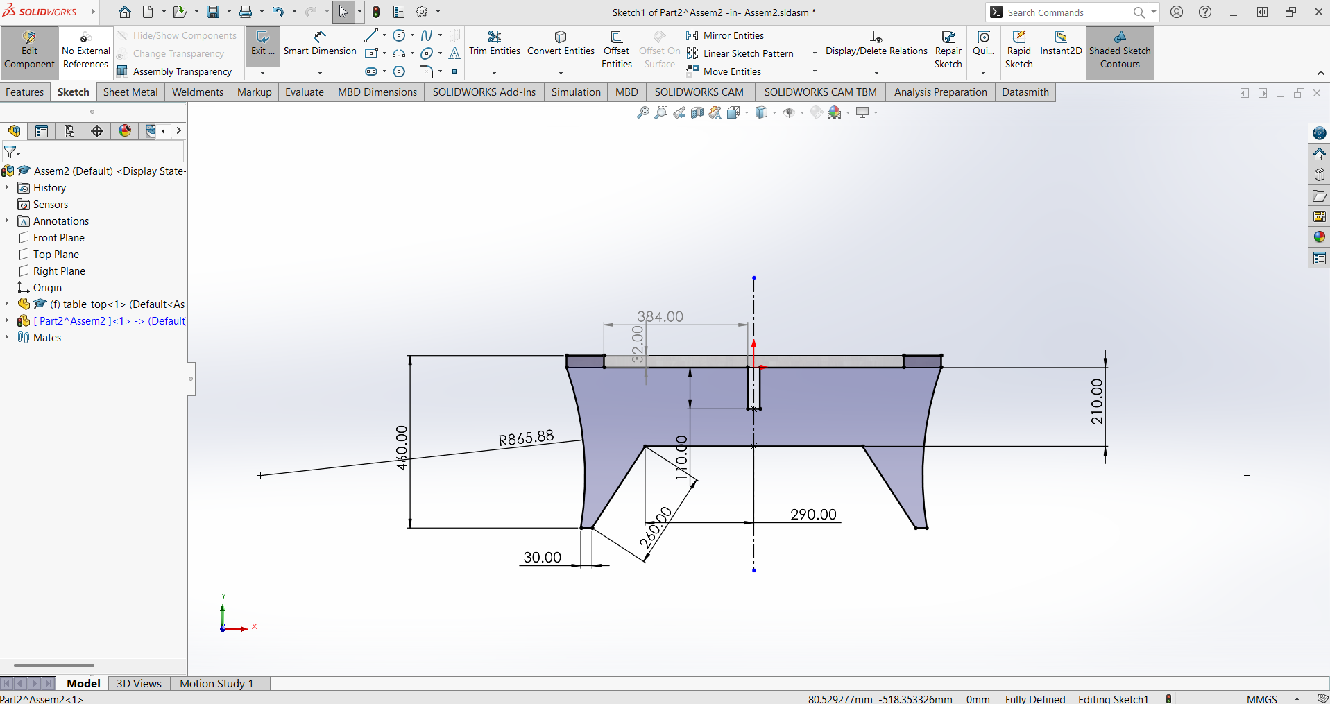
Used the Sketch tool to draw the 2D profile of each part, specifying precise dimensions.
Top Sketch
Foot 1 Sketch
Foot 2 Sketch
Figure: Drawing the 2D profiles for each part using the Sketch tool.
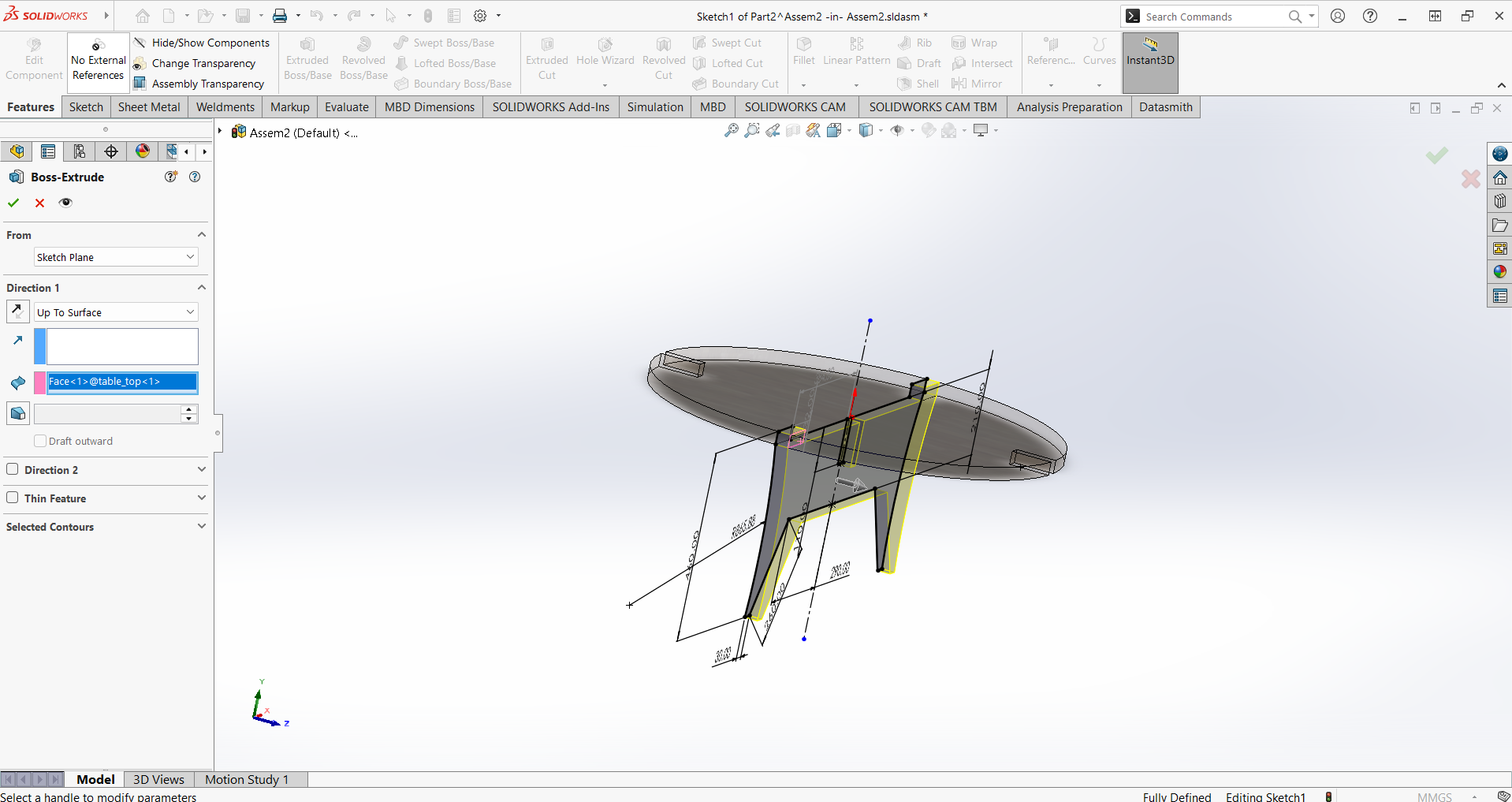
Extruded the sketches to the required thickness using the Extrude Boss/Base feature.
Top Extrude
Foot 1 Extrude
Foot 2 Extrude
Figure: Extruding each sketch to create 3D parts.
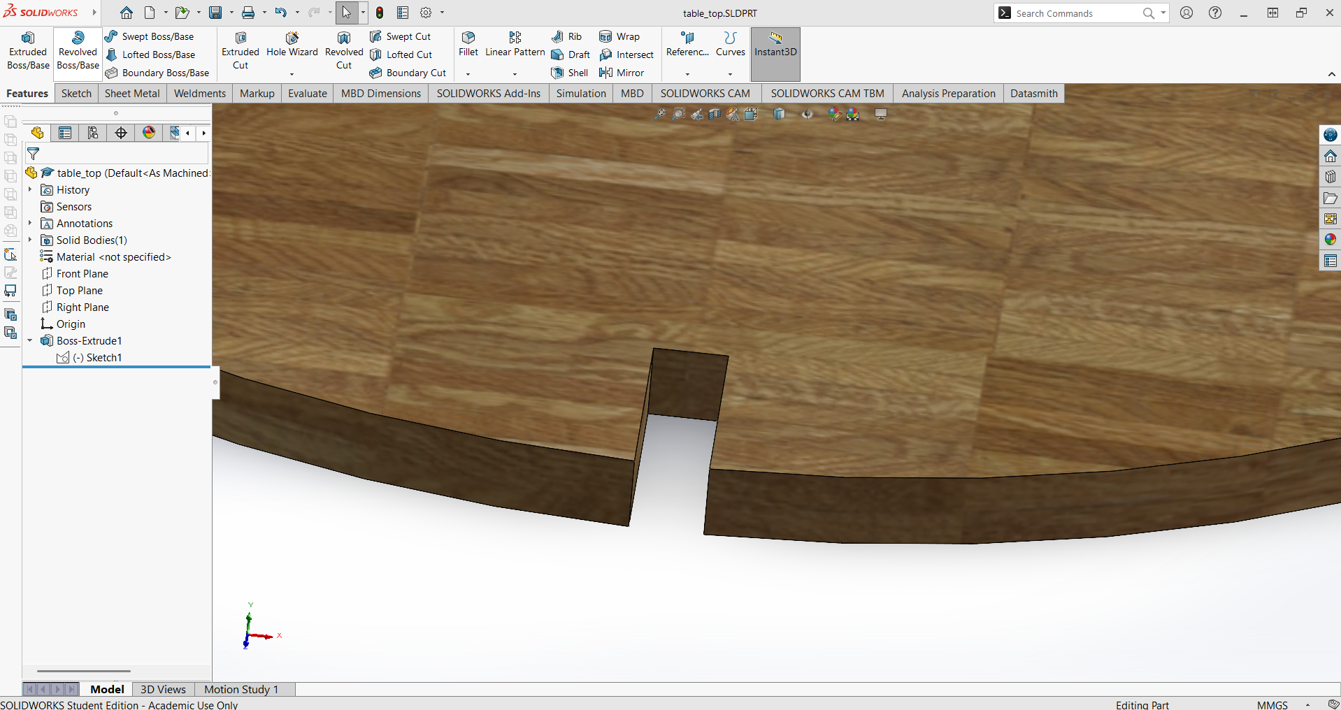
Added features such as slots, tabs, and holes for joinery and assembly.
Top Features
Foot 1 Features
Foot 2 Features
Figure: Adding slots, tabs, and holes for assembly to each part.
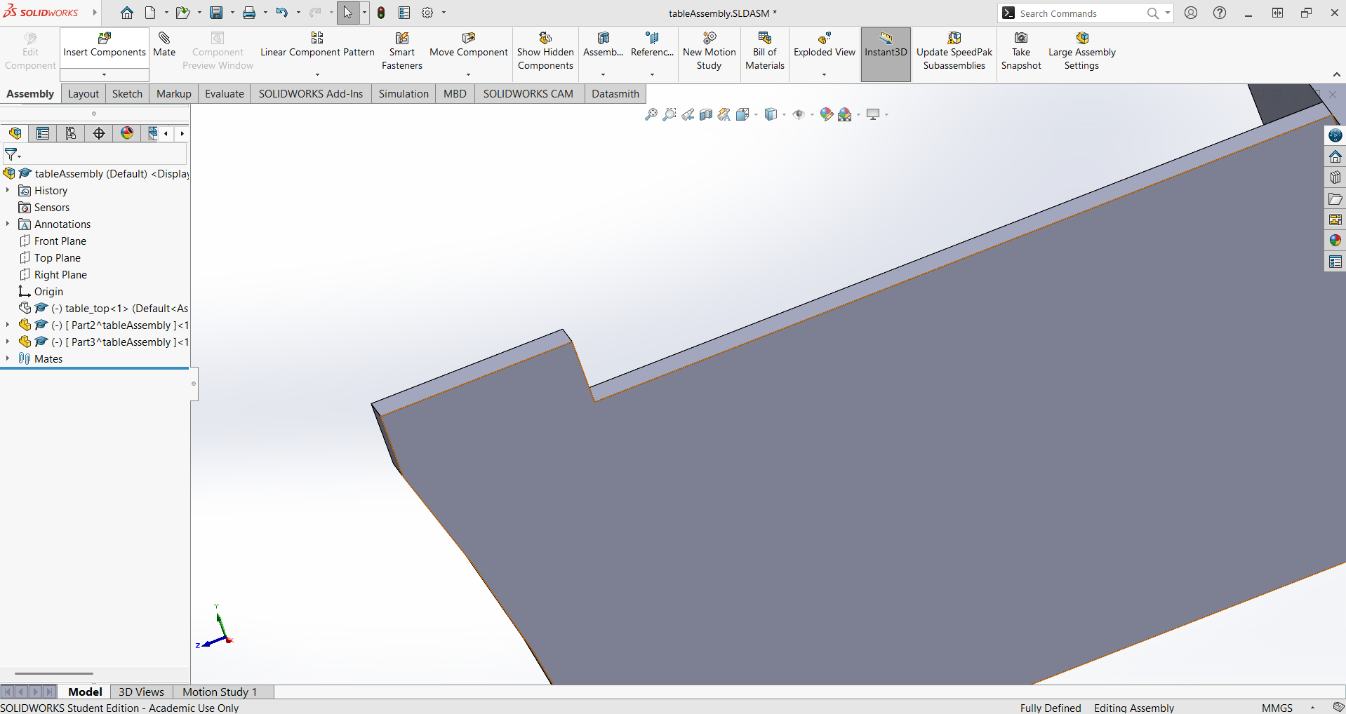
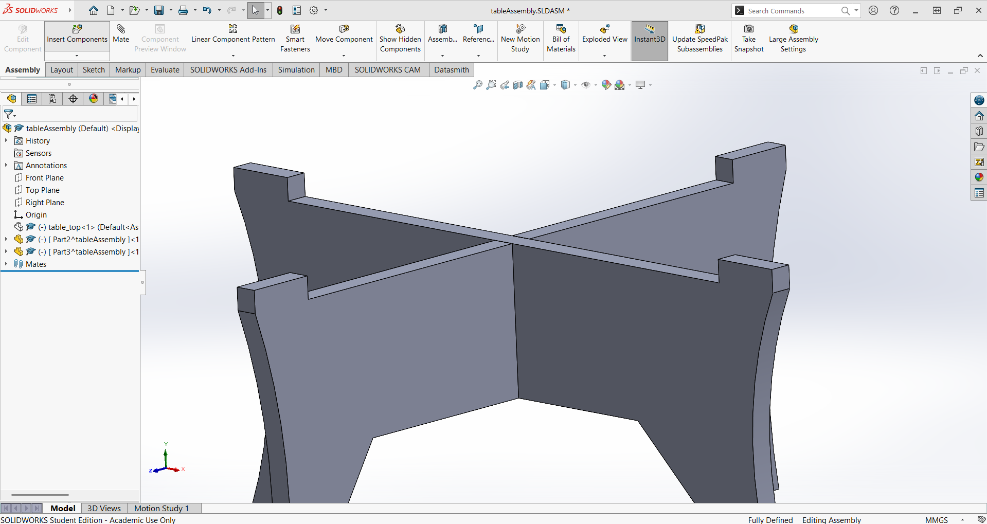
Assembly in SolidWorks:
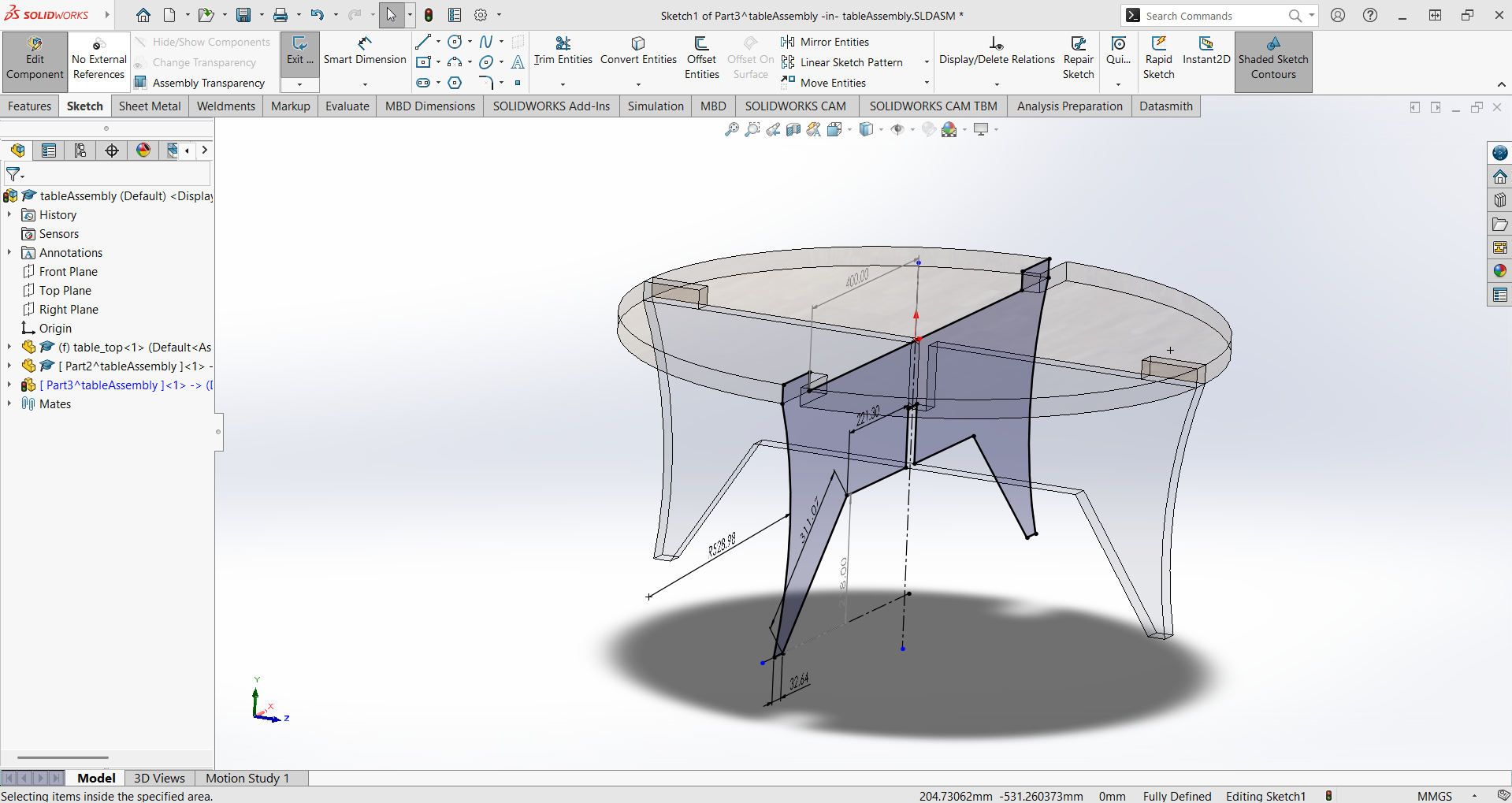
Created a new Assembly file and inserted all the individual parts.
Used Mate constraints to position and align the parts, ensuring proper fit and stability.
Checked for interferences and made adjustments to part dimensions if necessary.
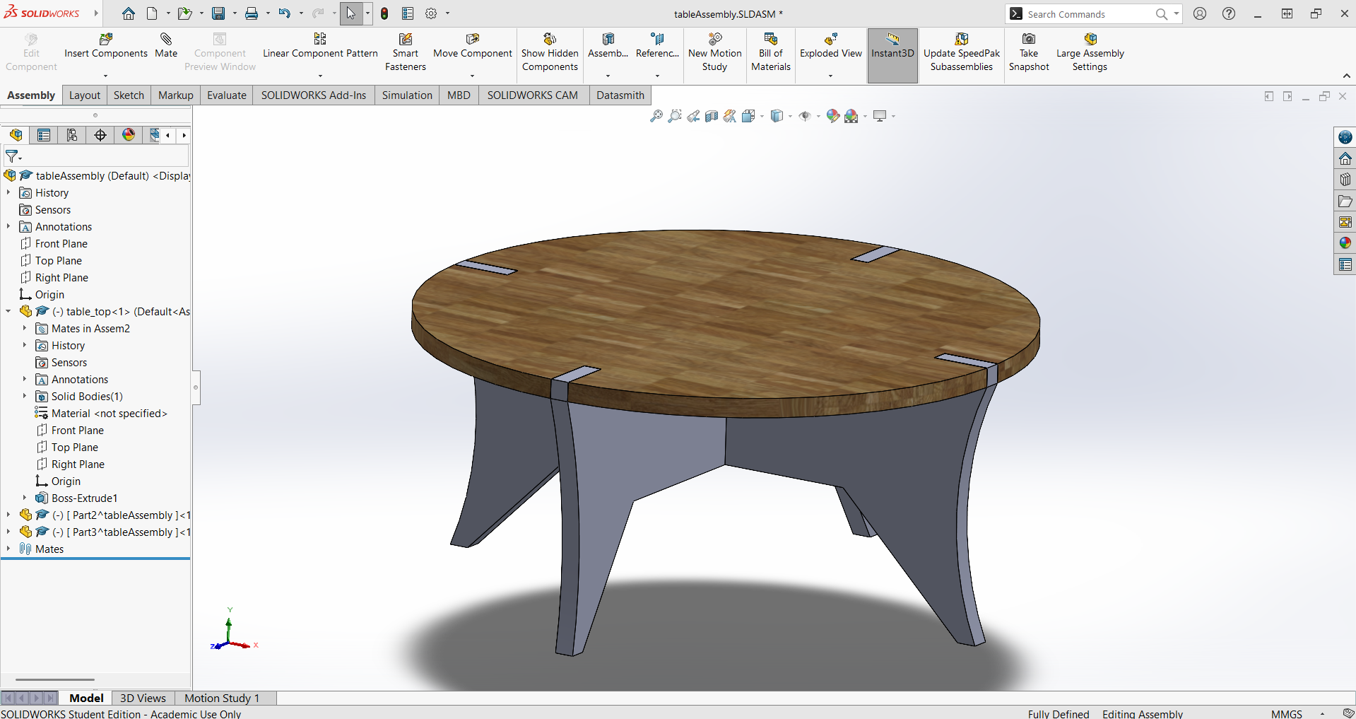
Assembly View:
Figure: Assembly view in SolidWorks showing all table parts fitted together.
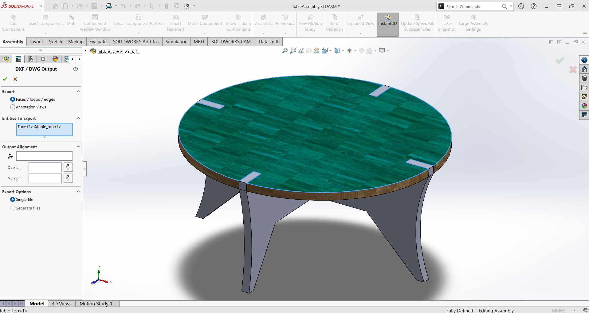
Exporting DXF Files:
I went to file, save as, and selected DXF. Next all i needed was to select the face to be saved as dxf for each part
Export to DXF/DWG option in SolidWorks
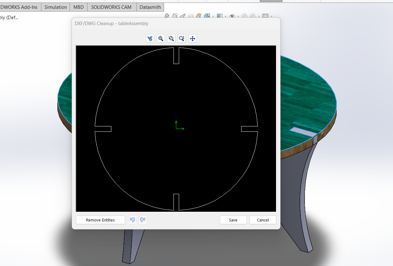
Chose the DXF format and saved each part's outline as a separate DXF file.
Saving part outline as DXF
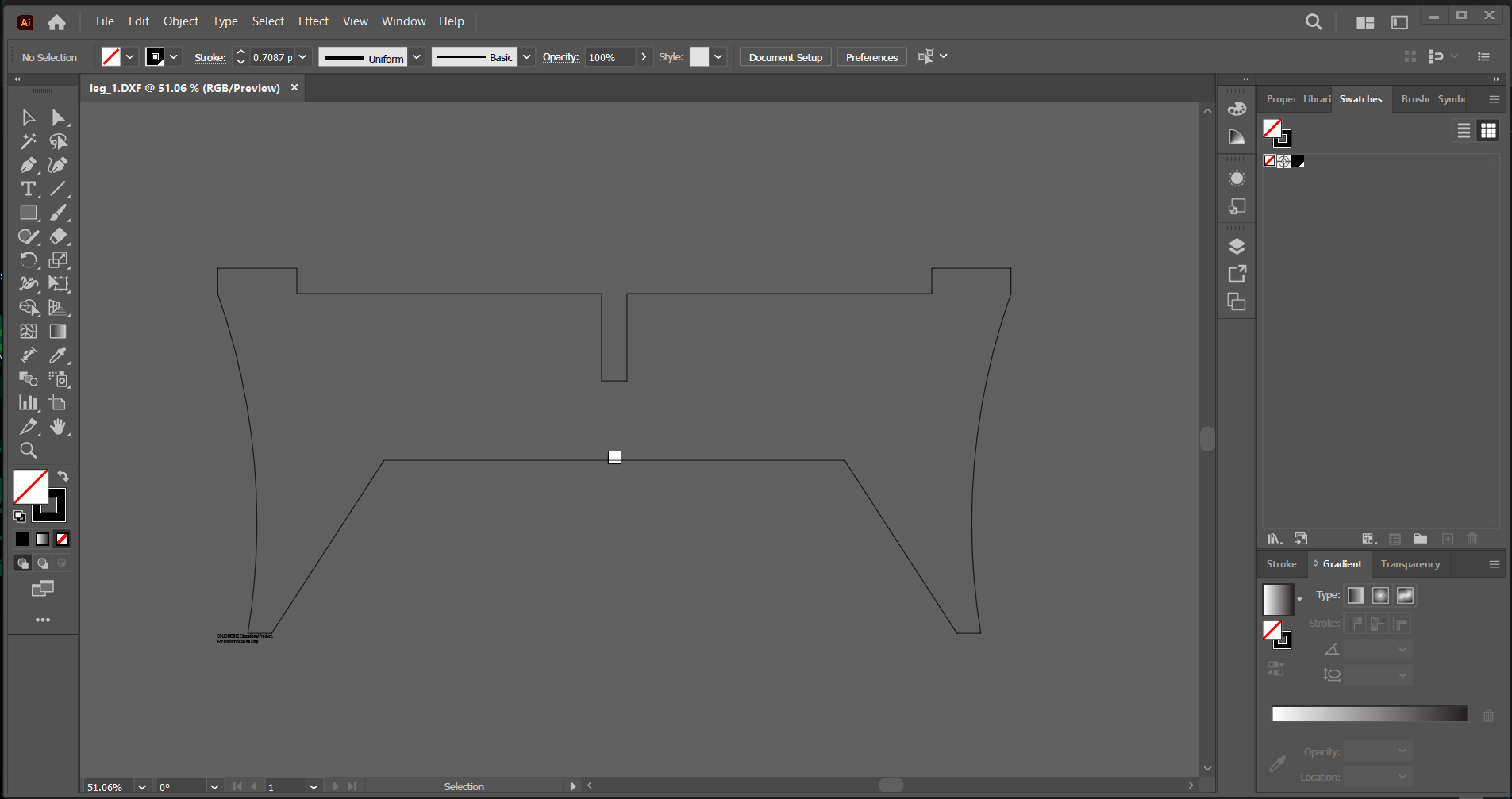
Verified the exported DXF files in a vector editing program (like Adobe Illustrator) to ensure accuracy and correct scaling.
Checking DXF in Illustrator
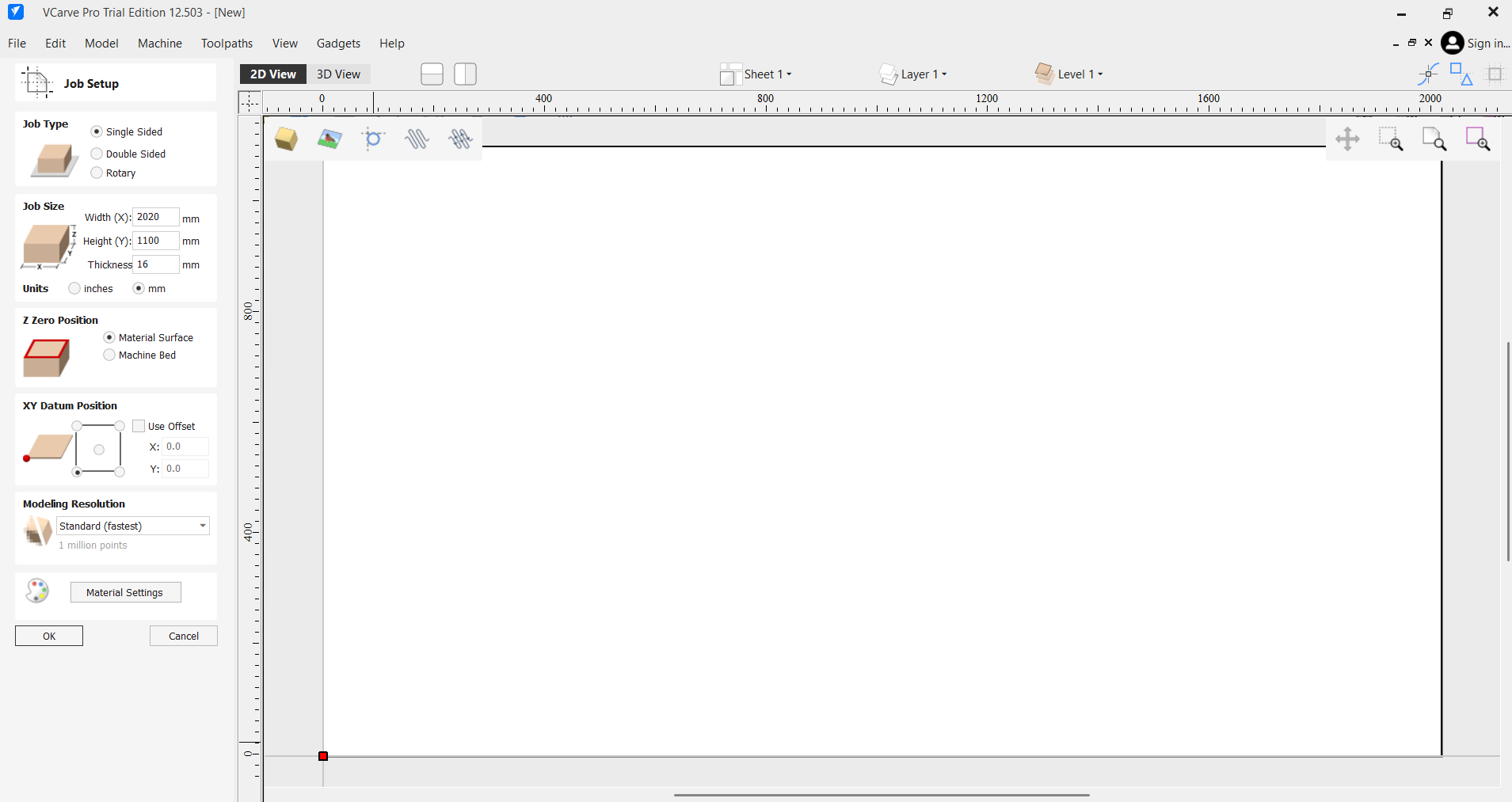
Creating Toolpaths for CNC:
First seting up, job type to single side, job size to the size of my flat pack coffee table and z zero to material surface.
Setting up the job in VCarve
Imported the DXF files into the CAM software provided with the CNC machine (I used VCarve).
Importing DXF files into VCarve
Arranged the parts efficiently on the virtual sheet to minimize material waste (nesting).
Nesting parts on the sheet in VCarve
Selected appropriate cutting tools (end mills) and set parameters such as cut depth, feed rate, and spindle speed based on the material (e.g., plywood or MDF).
Selecting tool and setting parameters
Assigned toolpaths for each part, specifying inside/outside cuts, 12 mm tabs for holding parts, and lead-in/lead-out moves. Lead-in and lead-out are short entry and exit paths that the cutting tool follows before starting and after finishing the main cut. They help prevent marks or defects at the start and end points of the cut by allowing the tool to enter and exit the material smoothly. Each part was in a single nested configuration and had no special features, so only one tool was used for all operations.
Assigning toolpaths and tabs
A 6mm end mill was used for the cuts, with a feed rate of 1000 mm/min and a spindle speed of 18000 RPM.
Pass depth was set to 3mm, and the total cut depth was 18mm for the tabletop and 18mm for the feet as well.
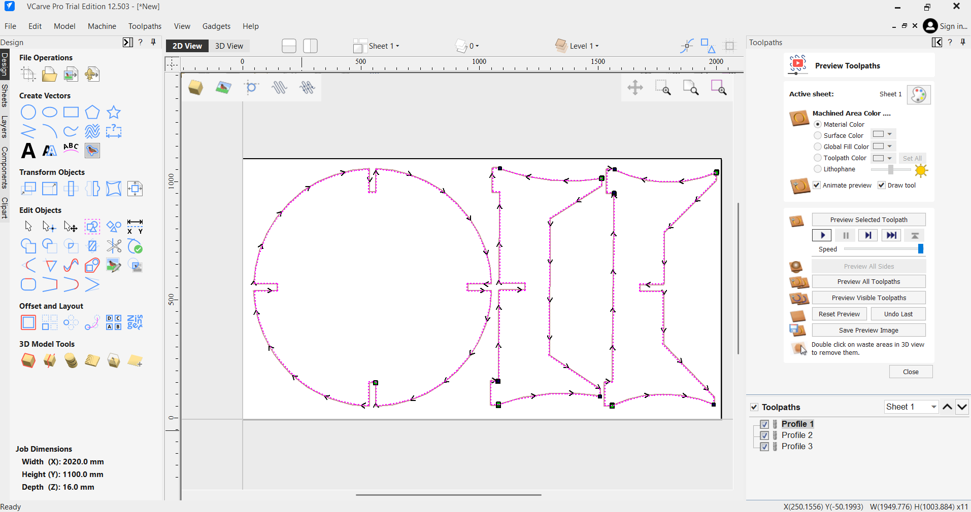
Simulated the toolpaths to check for errors or collisions.
Simulating toolpaths in VCarve
Simulation of the CNC toolpaths in VCarve
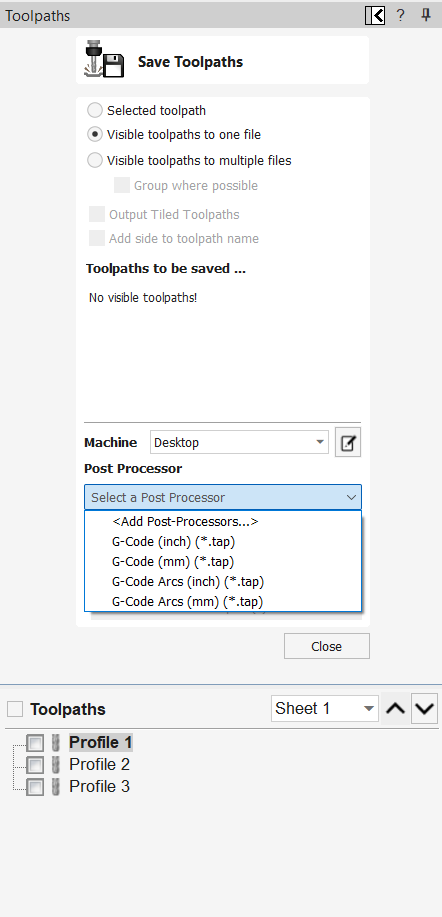
Exported the final G-code or machine file for the CNC router.
Exporting G-code for CNC
Fabrication & Assembly:
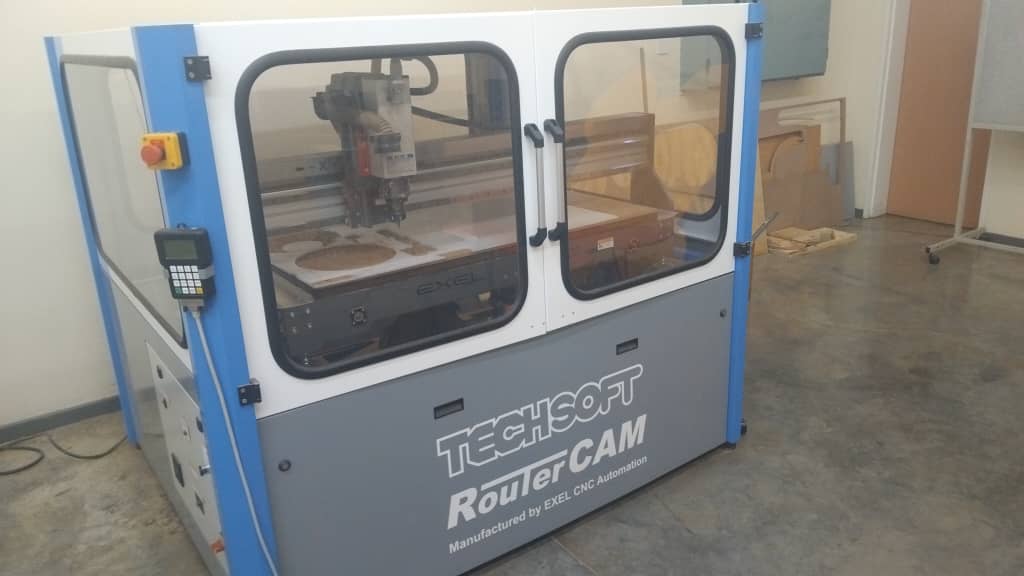
Unfortunately, our LAB's CNC machine was down during this week, and the new Unipod machines are still being commissioned and are not yet operational.
LAB CNC machine currently out of service
Unipod machines in the process of commissioning
Video: Unipod CNC machines being set up in the lab
As a result, I was unable to fabricate and assemble my table this week. Once the machines are operational, I will proceed with the cutting and assembly steps as planned.
Download Project Files
You can download all the design files (SolidWorks parts, DXF exports, and toolpaths) used for this project as a ZIP archive:
 Top Part
 Top Sketch
 Foot 1 Sketch
 Foot 2 Sketch
 Top Extrude
 Foot 1 Extrude
 Foot 2 Extrude
 Top Features
 Foot 1 Features
 Foot 2 Features
 Export to DXF/DWG option in SolidWorks
 Saving part outline as DXF
 Checking DXF in Illustrator
 Setting up the job in VCarve
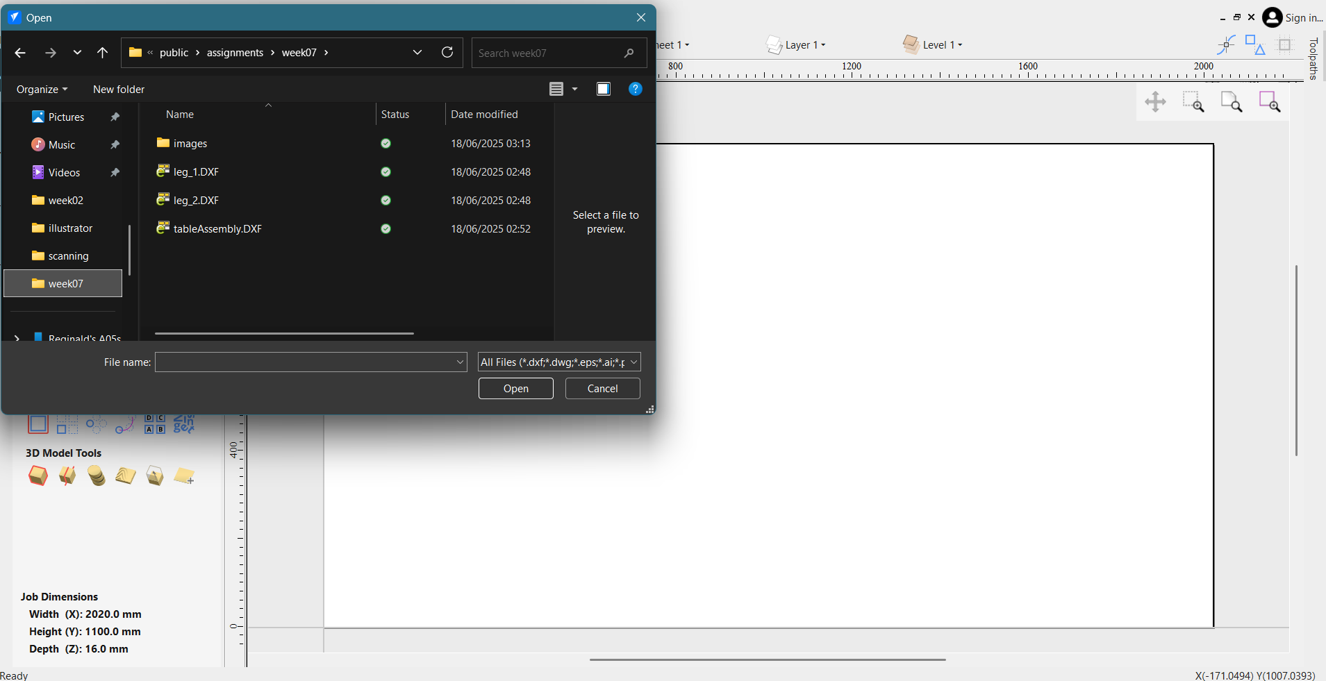 Importing DXF files into VCarve
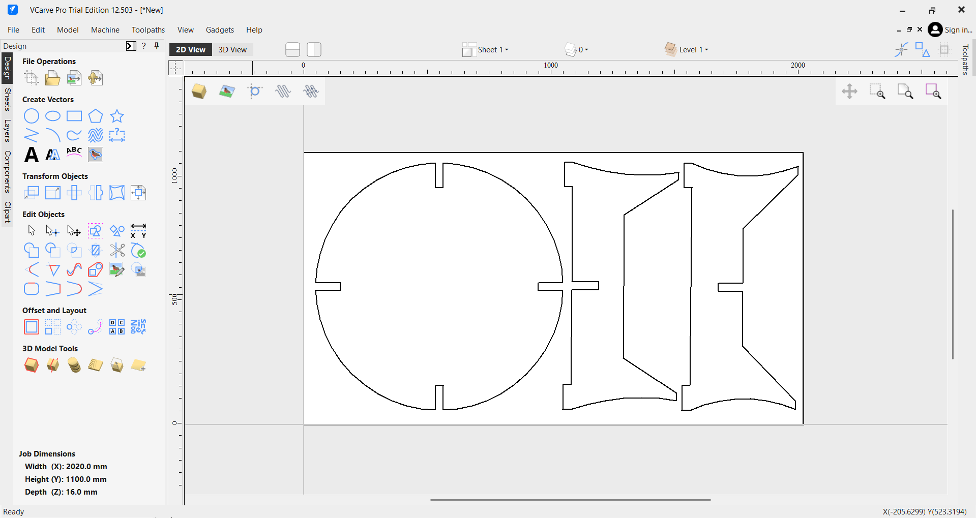 Nesting parts on the sheet in VCarve
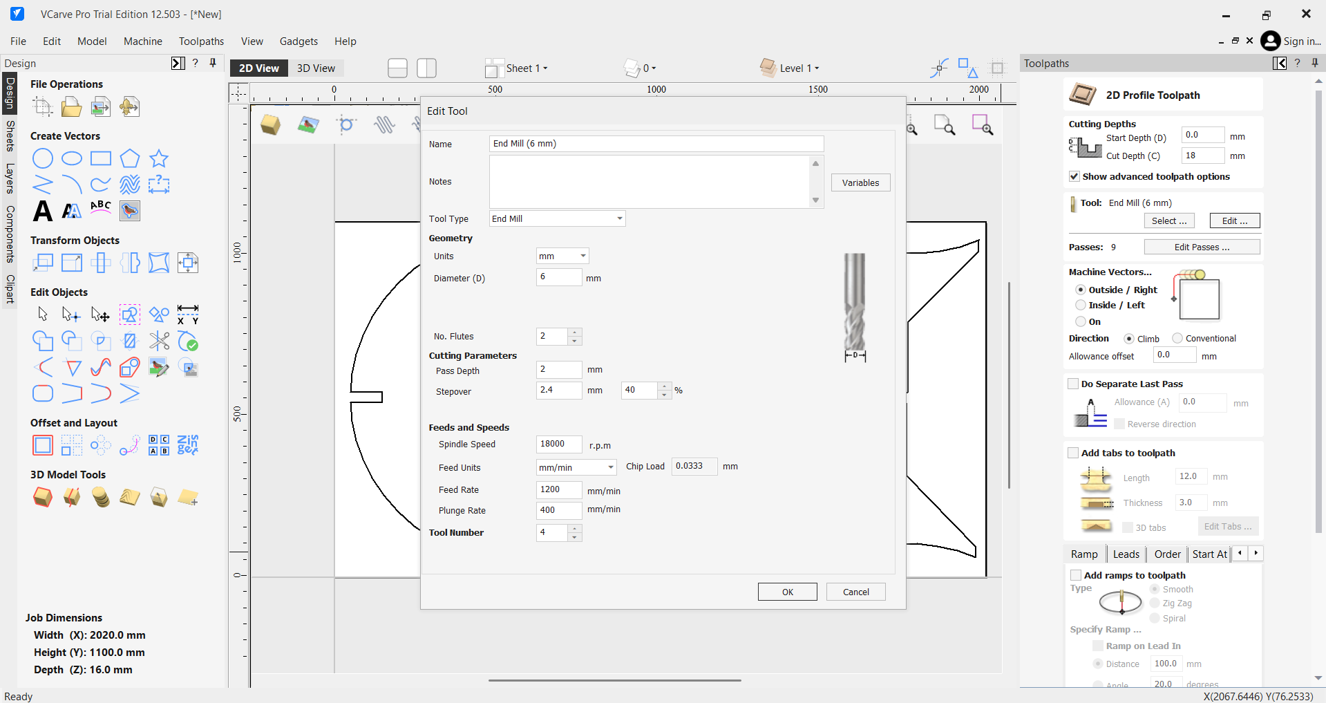 Selecting tool and setting parameters
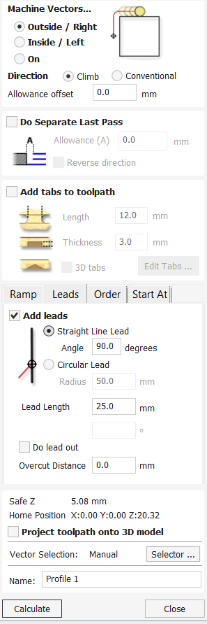 Assigning toolpaths and tabs
 Simulating toolpaths in VCarve
 Exporting G-code for CNC
 LAB CNC machine currently out of service
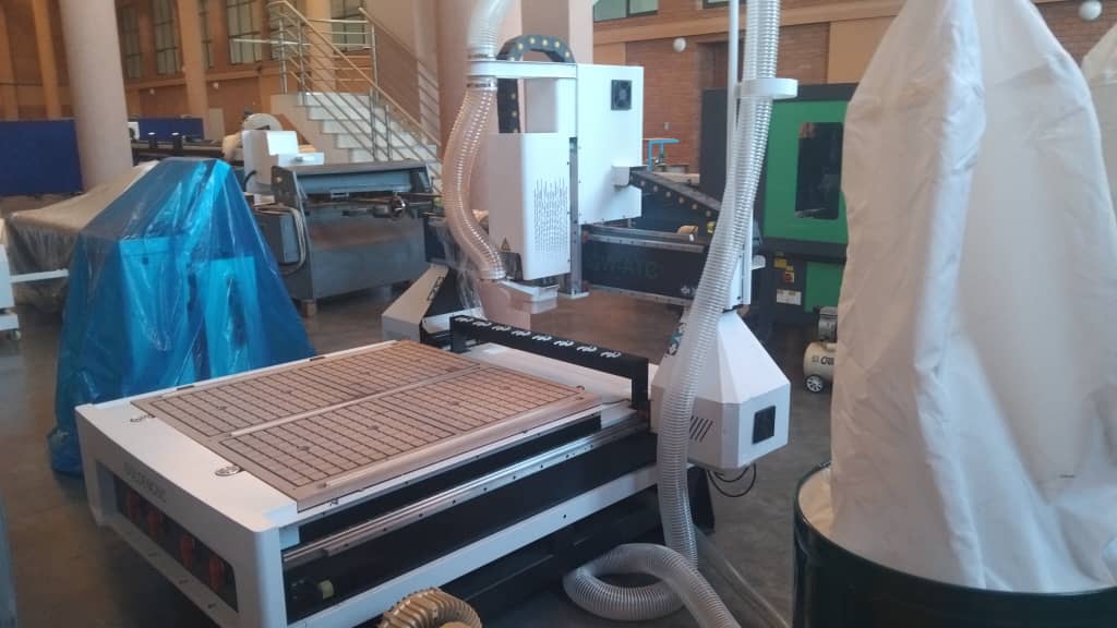 Unipod machines in the process of commissioning