This week focuses on exploring 3D printing and scanning technologies. The assignments are divided into two parts: a group assignment and an individual assignment.
In the group assignment, we tested the design rules for our 3D printer(s) to understand their capabilities and limitations. This involved evaluating parameters such as layer height, overhangs, bridging, and resolution. Our findings and observations are documented on the group work page, with personal reflections included on our individual pages.
For the individual assignment, we designed and 3D printed an object that could not be easily made using subtractive manufacturing methods. Additionally, we 3D scanned an object to explore the process of digitizing physical objects. These tasks helped us learn about the design considerations for additive manufacturing and the workflows for 3D scanning and printing.
Group Assignment
For the group assignment, we tested the design rules for our 3D printer(s) to understand their characteristics and limitations. We documented our findings on the group work page and reflected on our individual pages about what we learned regarding the capabilities of our printer(s). The group work documentation can be found here.
Individual Assignment
For the individual assignment, we designed and 3D printed an object (small, a few cm³, limited by printer time) that could not be easily made using subtractive manufacturing methods. This task helped us identify the advantages and limitations of 3D printing, such as its ability to create complex geometries and the constraints of layer-based fabrication. Additionally, we 3D scanned an object to explore how scanning technology can be used to digitize physical objects, demonstrating the workflows and considerations involved in the process.
The Task At Hand?
Subtractive manufacturing methods, such as milling or turning, are limited in their ability to create certain geometries. For example, objects with internal cavities, intricate lattice structures, or overhangs that lack support cannot be easily produced using these methods. 3D printing, on the other hand, excels at creating such complex shapes due to its layer-by-layer additive approach.
Bellow is a list of features that categorize parts or shapes that can only be made through 3d printing:
Internal cavities or hollow structures that are inaccessible by cutting tools.
Complex lattice or mesh designs for lightweight yet strong components.
Overhangs and unsupported geometries that would collapse in subtractive processes.
Organic or freeform shapes that are difficult to machine.
Interlocking parts or assemblies printed in one go without requiring assembly.
Making An Object
Designing a Complex Mechanical Heart in SolidWorks
Below are the steps I followed to design a complex mechanical heart in SolidWorks, along with the considerations I took at each step to ensure it could be 3D printed in one piece with moving parts:
Research and Conceptualization:
I started by researching and studying existing mechanical designs. This helped me understand the key components and movements I needed to replicate. I also considered the limitations of 3D printing, such as minimum feature size and tolerances for moving parts.
I watched a video by Make With Tech (MakeWithTech) on YouTube that provided a detailed overview of the design process for an object with moving parts for 3D printing. The video covered the design considerations, assembly, and printing process, which helped me understand the complexities involved in creating such a model.
This video showed different toys from simple to complex that could not be made with subtractive manufacturing methods because they had cavities and overhangs whcih facilitated joints and moving parts which were not possible with subtractive manufacturing methods. and this is where i got the idea to recplicate from scratch the mechanical heart that was shown in the video.
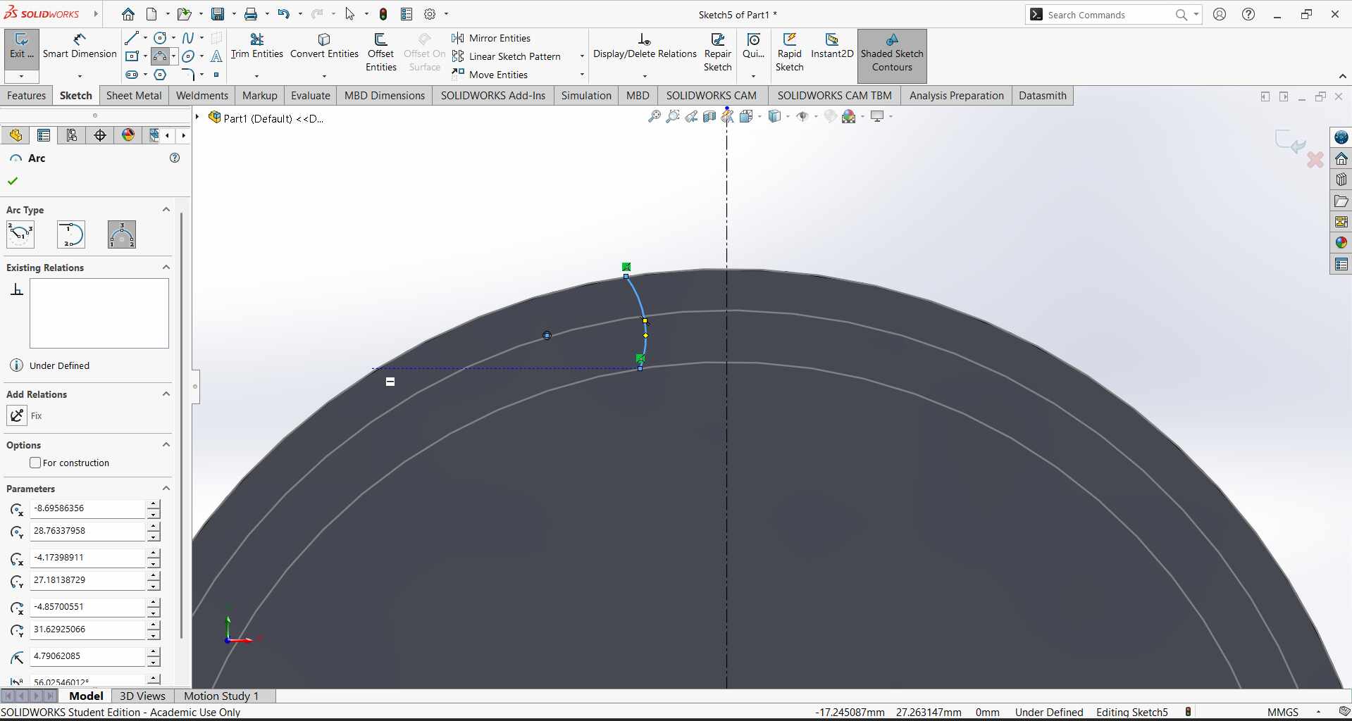
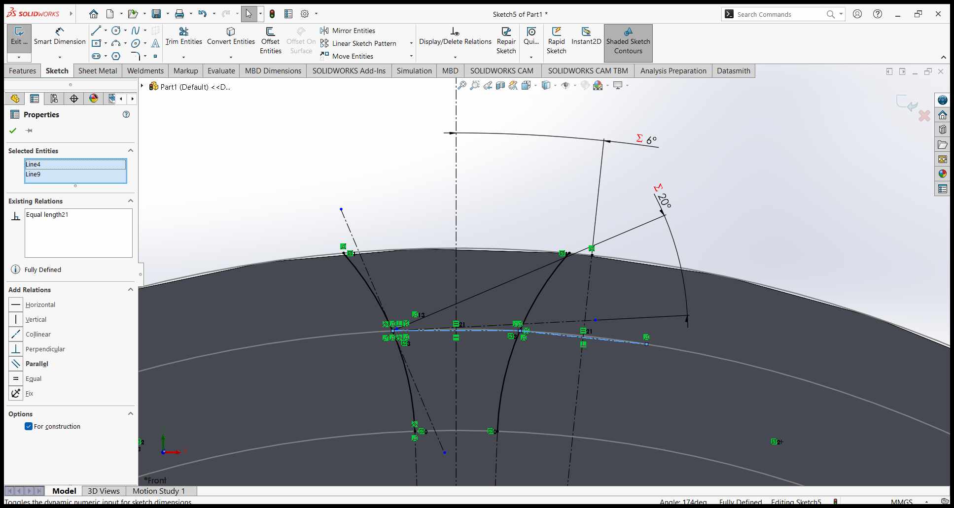
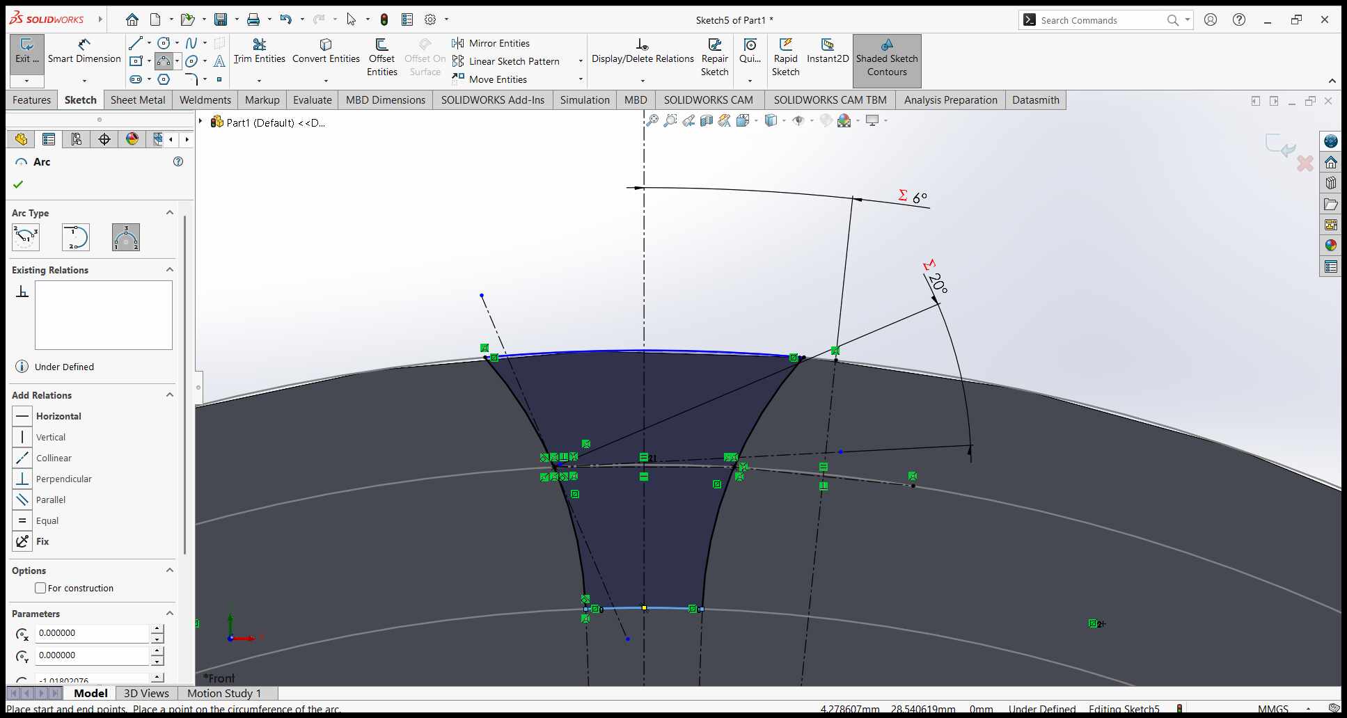
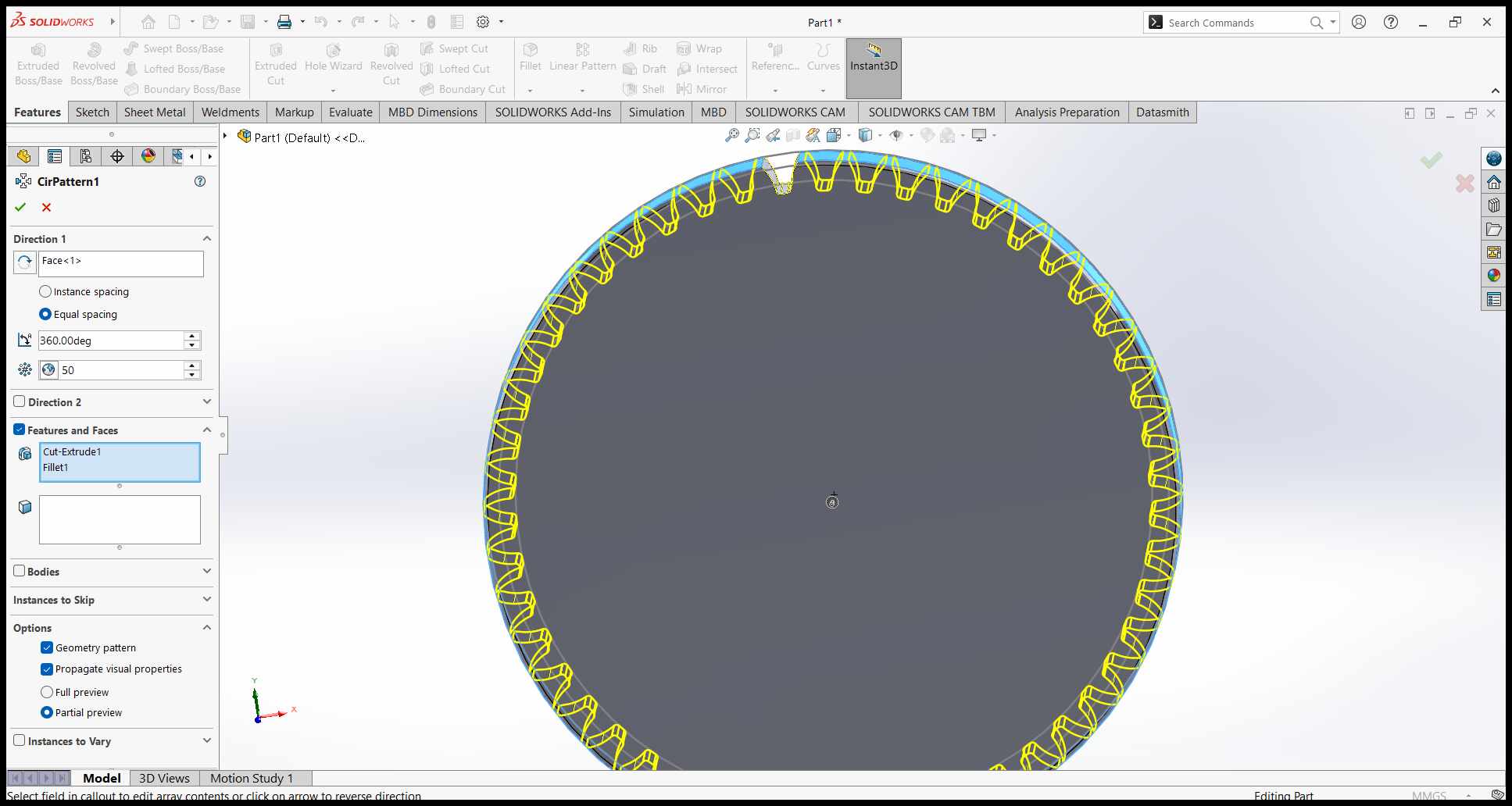
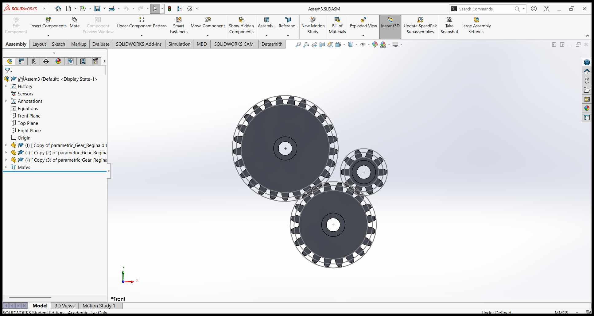
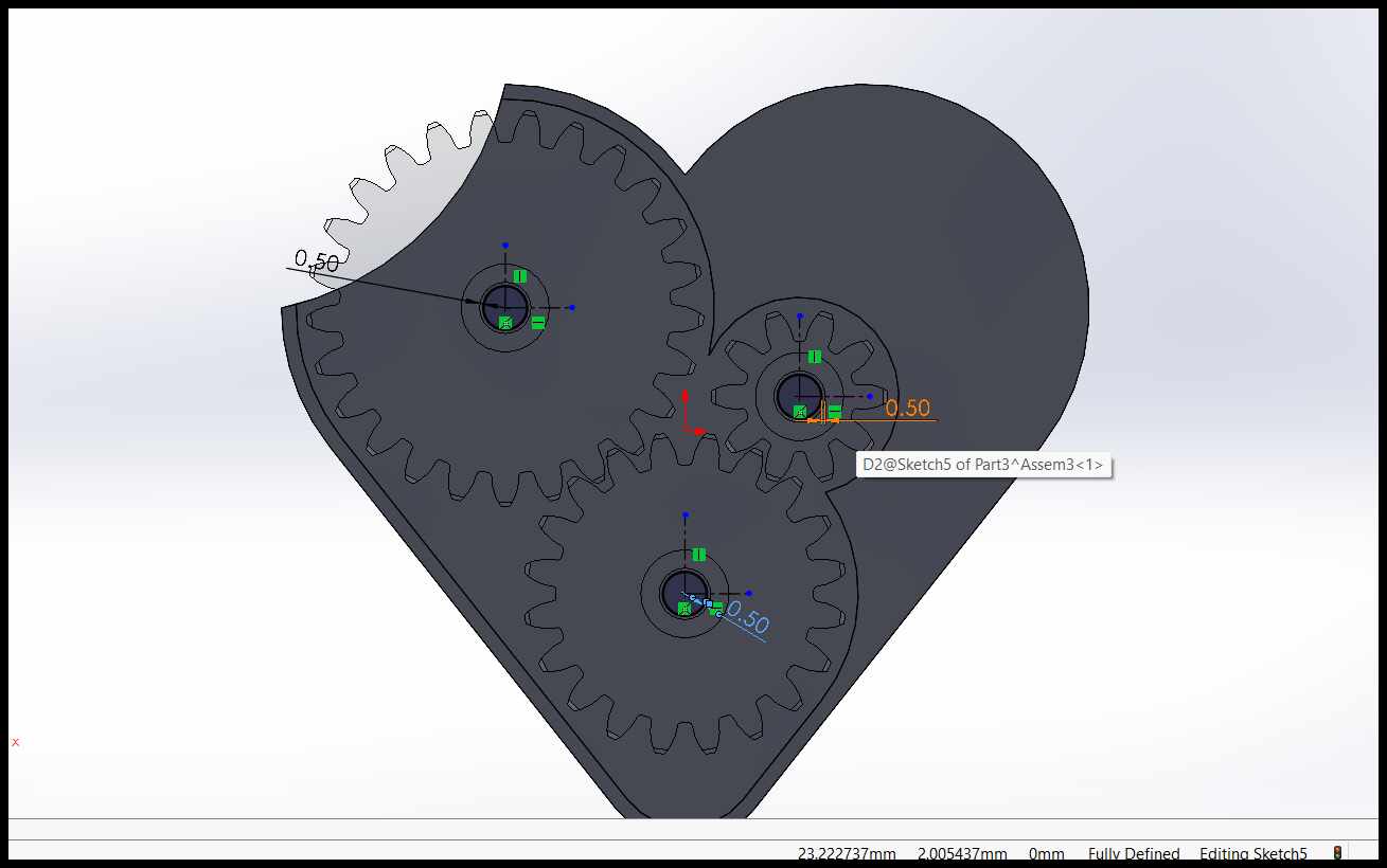
Sketching a Parametric Gear
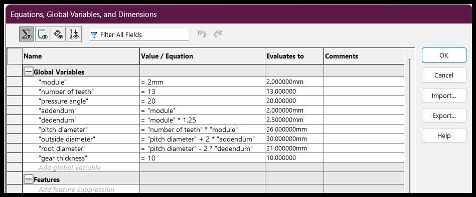
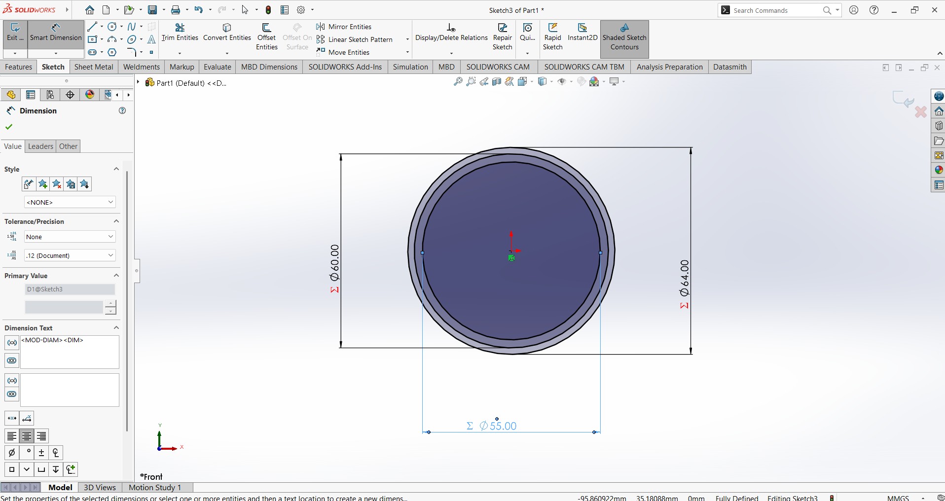
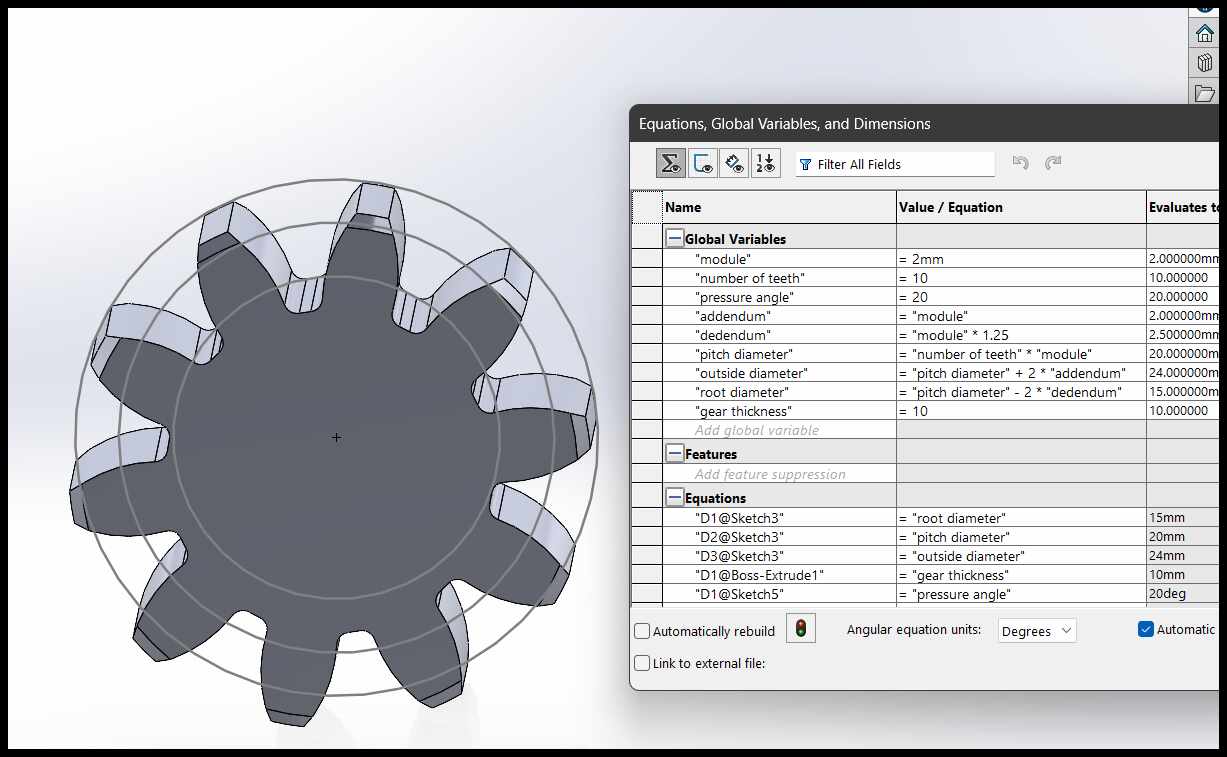
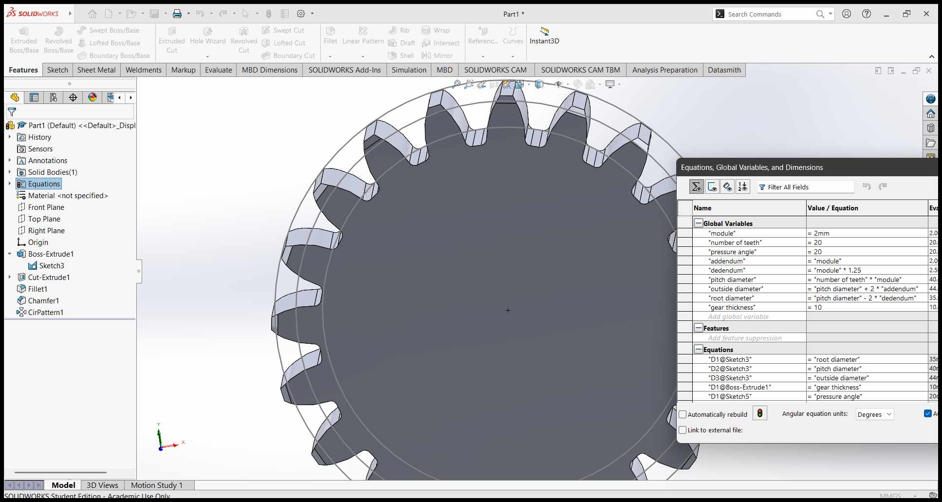
I started by sketching a parametric gear in SolidWorks. This involved defining the gear's parameters, such as the number of teeth, pitch diameter, and pressure angle. I used equations to ensure that the gear could be easily modified later if needed. This is because I need the gears of my mechanical heart to be different sized so this approach prevents redrawing every gear.
Parameters for the gears?
Module:
The module is the size of the gear teeth. It is calculated as the ratio of the pitch diameter to the number of teeth. A larger module means bigger teeth.
Number of Teeth:
This is the total count of teeth on the gear. It determines how the gear meshes with other gears and affects the gear ratio.
Pressure Angle:
The pressure angle is the angle between the gear tooth and the line of action. It affects the strength and smoothness of the gear's operation.
Addendum:
The addendum is the height of the gear tooth above the pitch circle. It defines how far the teeth extend outward.
Dedendum:
The dedendum is the depth of the gear tooth below the pitch circle. It defines the space between the teeth for meshing with another gear.
Pitch Diameter:
The pitch diameter is the diameter of the pitch circle, where the teeth of two gears effectively mesh. It is a key dimension for gear design.
Outside Diameter:
The outside diameter is the total diameter of the gear, including the tips of the teeth. It is larger than the pitch diameter.
Root Diameter:
The root diameter is the diameter of the base of the gear teeth, excluding the teeth themselves. It is smaller than the pitch diameter.
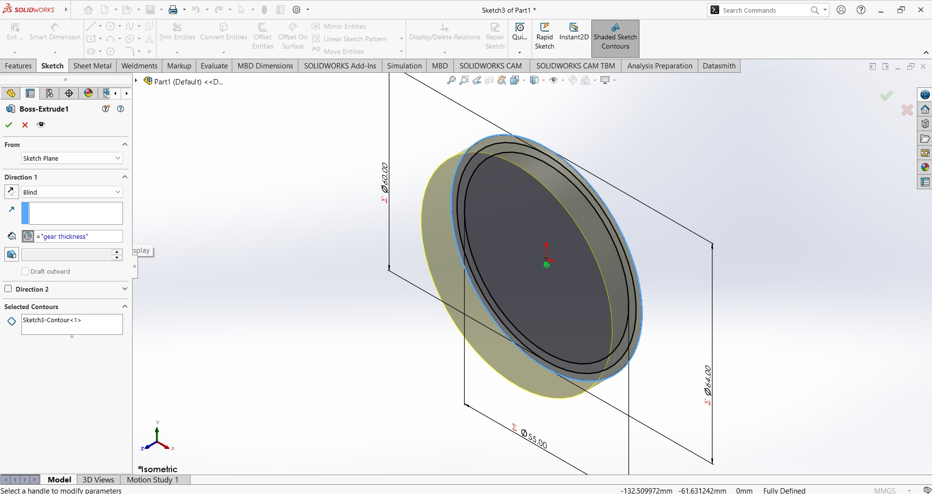
Gear Thickness:
The gear thickness is the width of the gear along its axis. It determines the strength and durability of the gear.
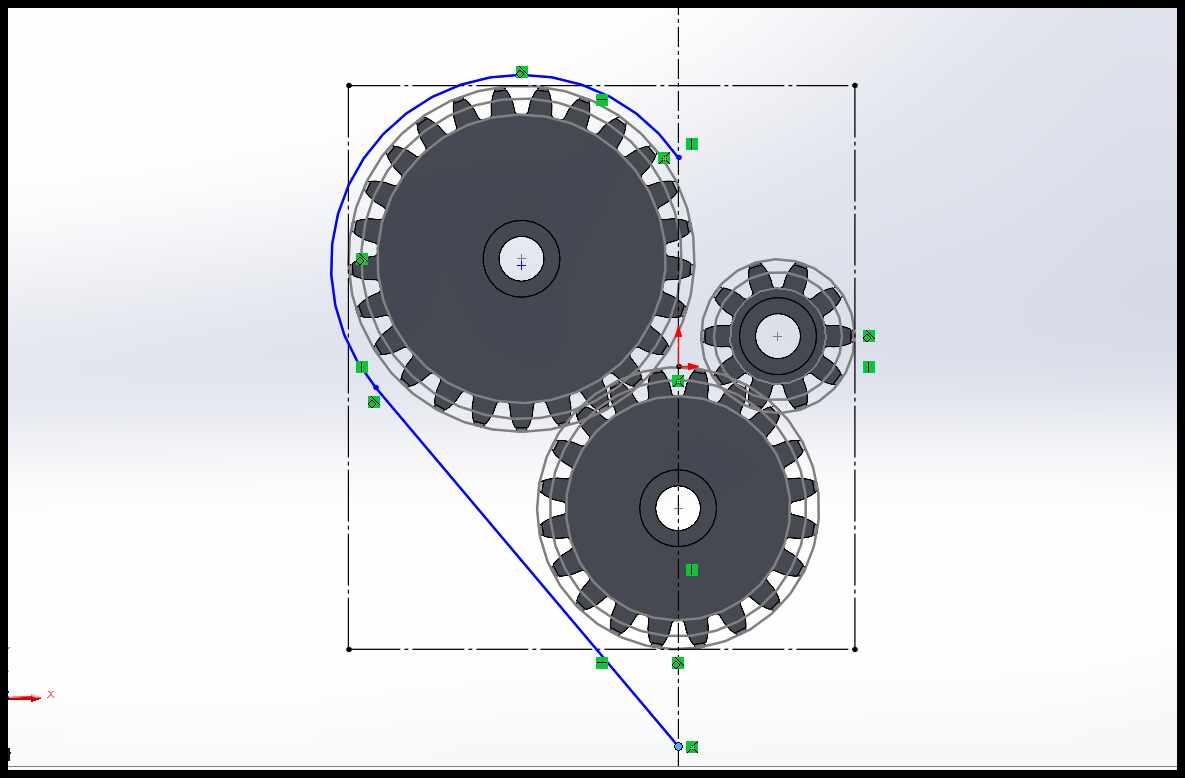
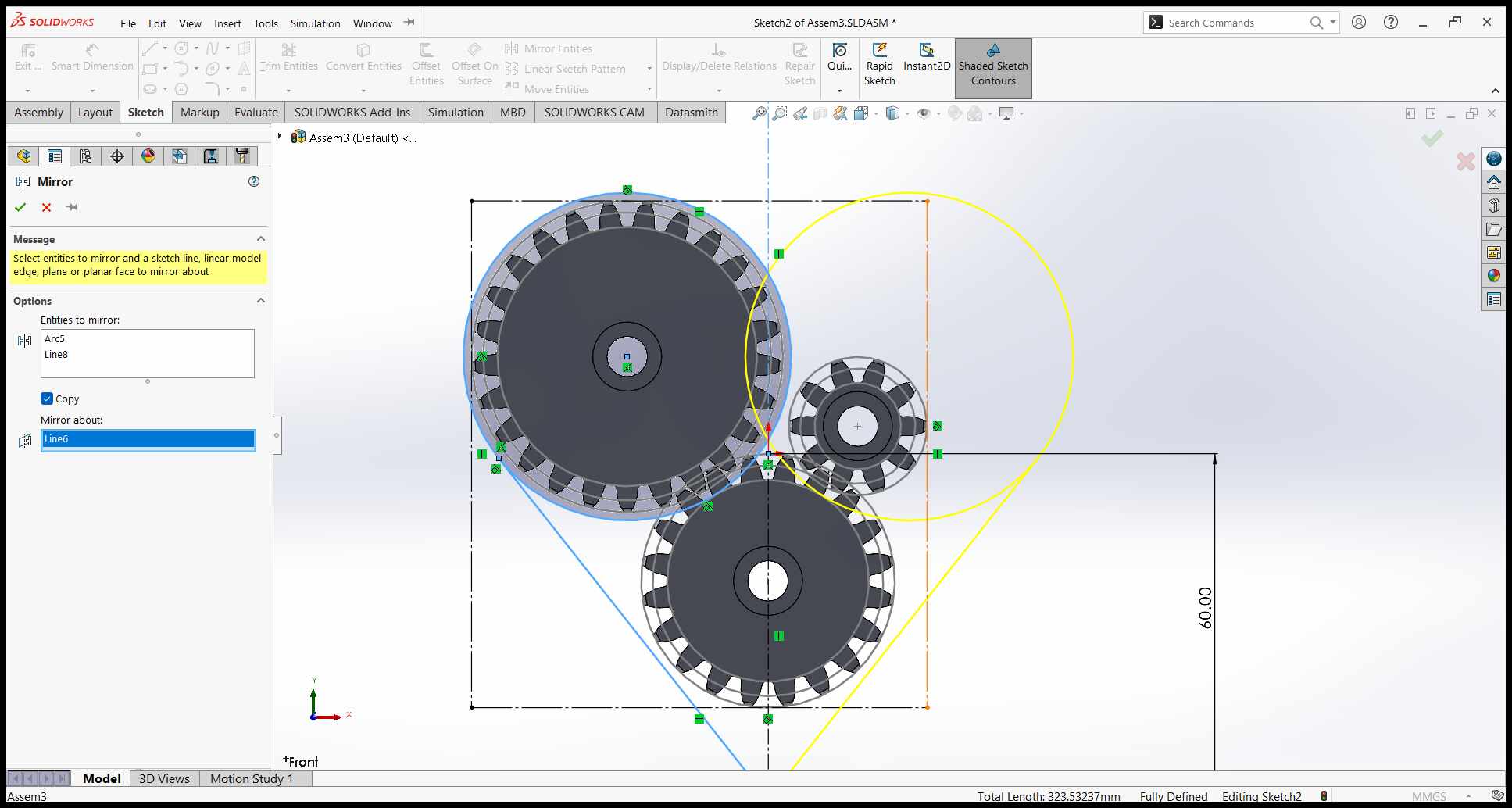
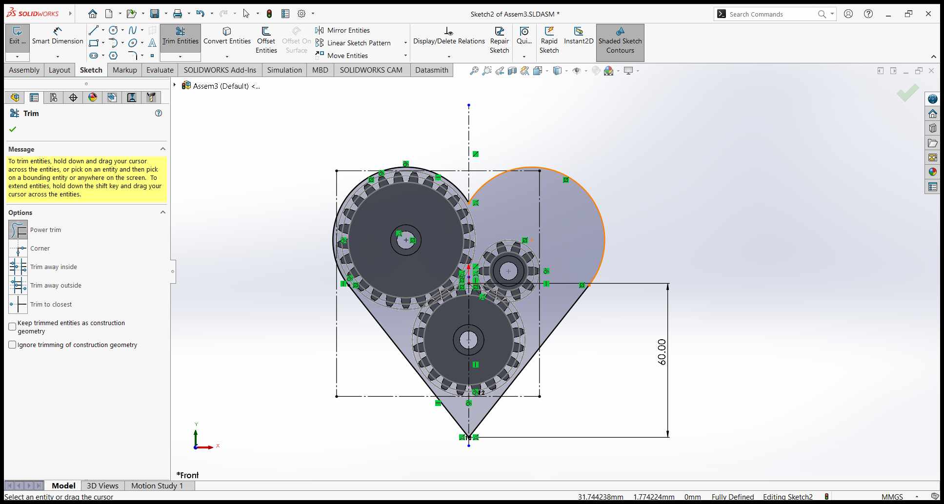
Sketching the Base Shape:
Using SolidWorks, I created a 2D sketch of the heart's outer shape. I ensured the design was symmetrical and accounted for the overall size constraints of the 3D printer's build volume.
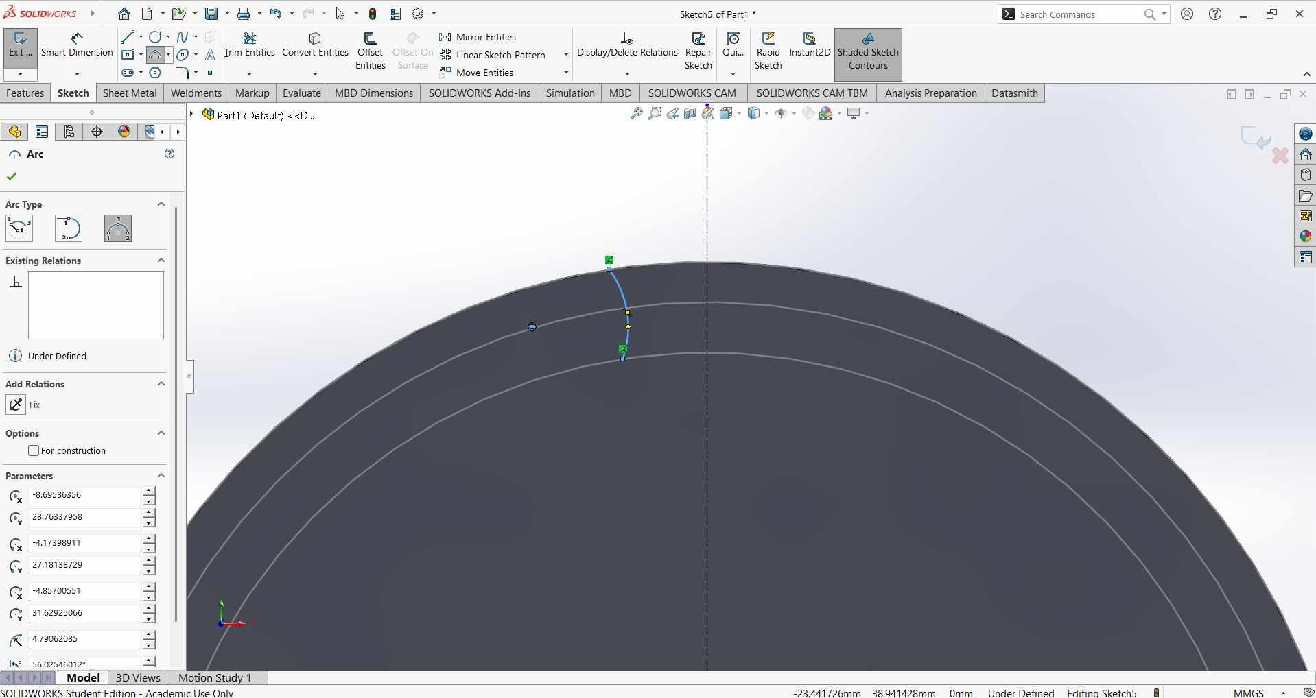
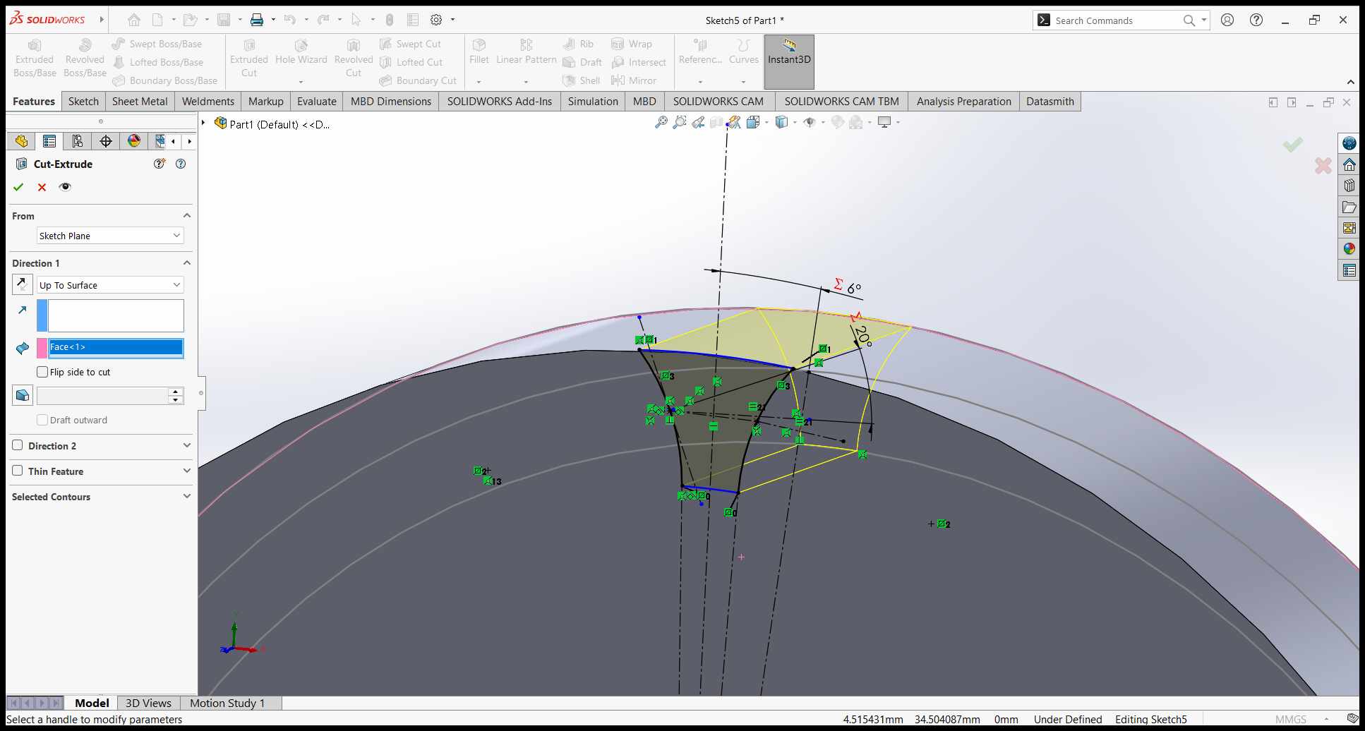
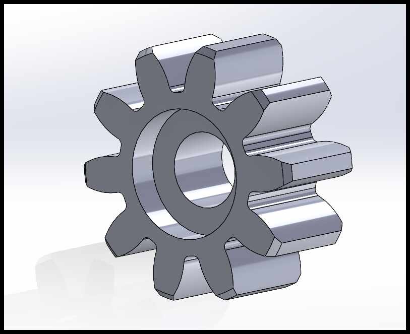
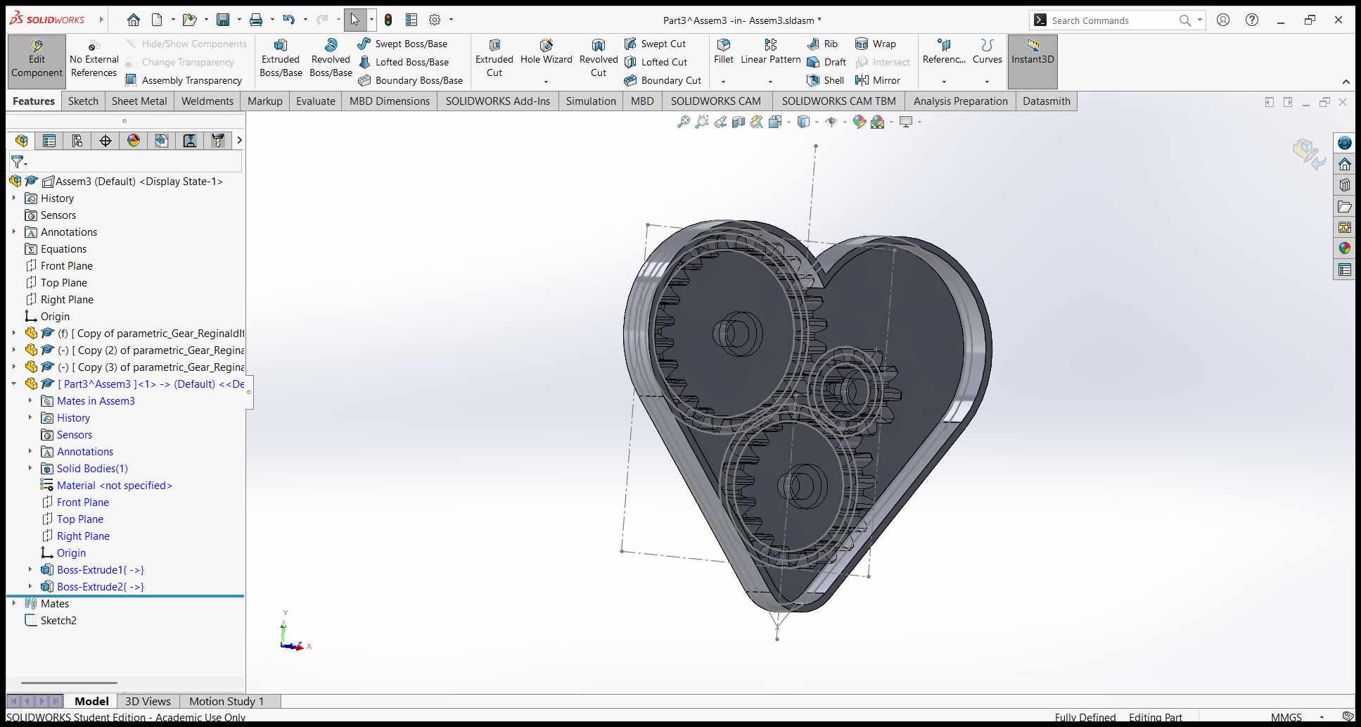
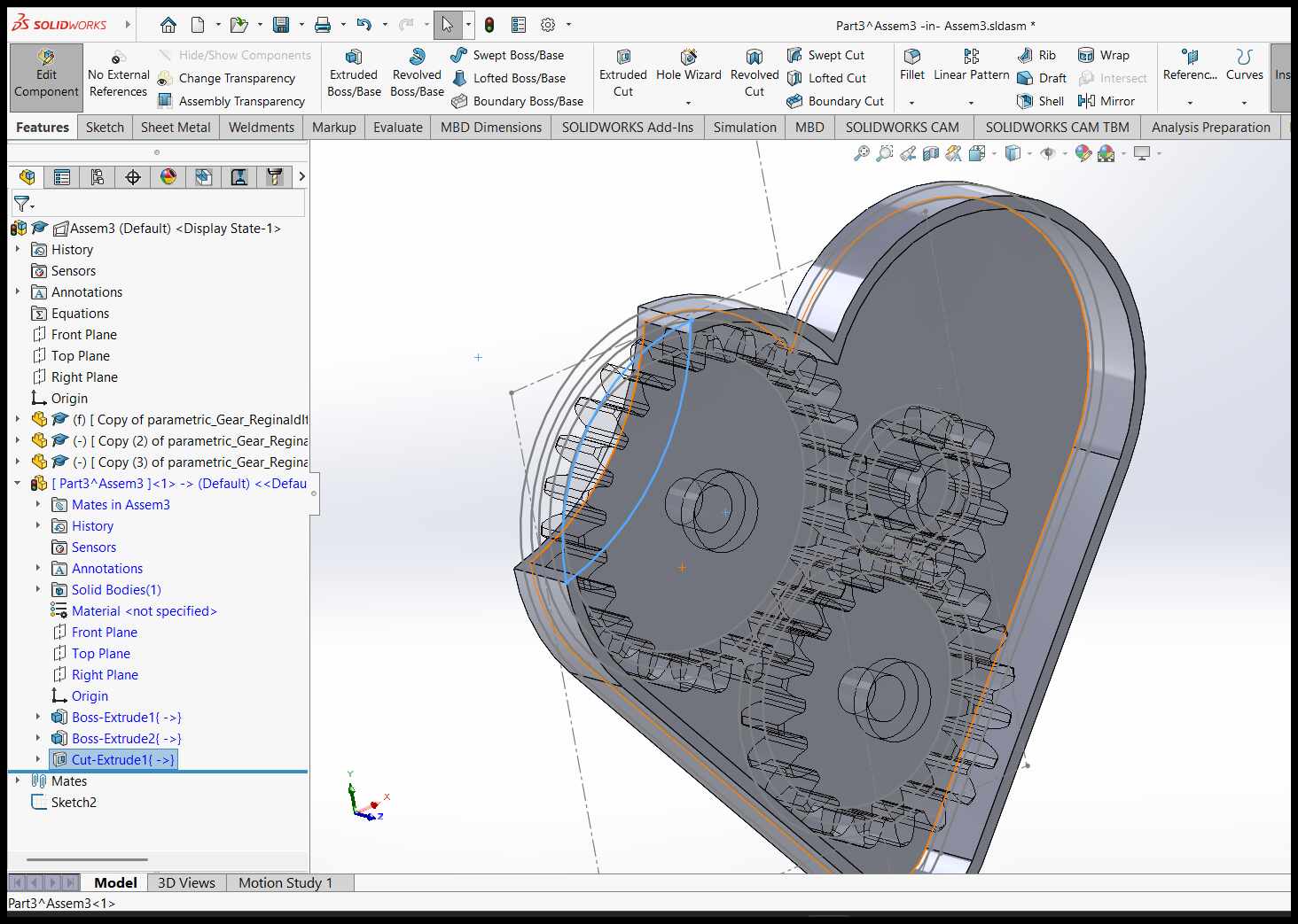
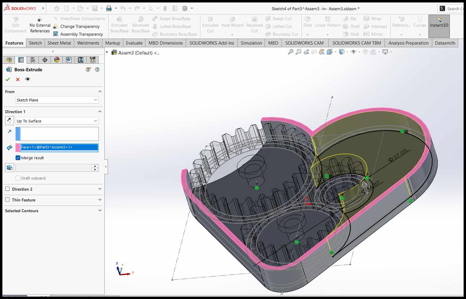
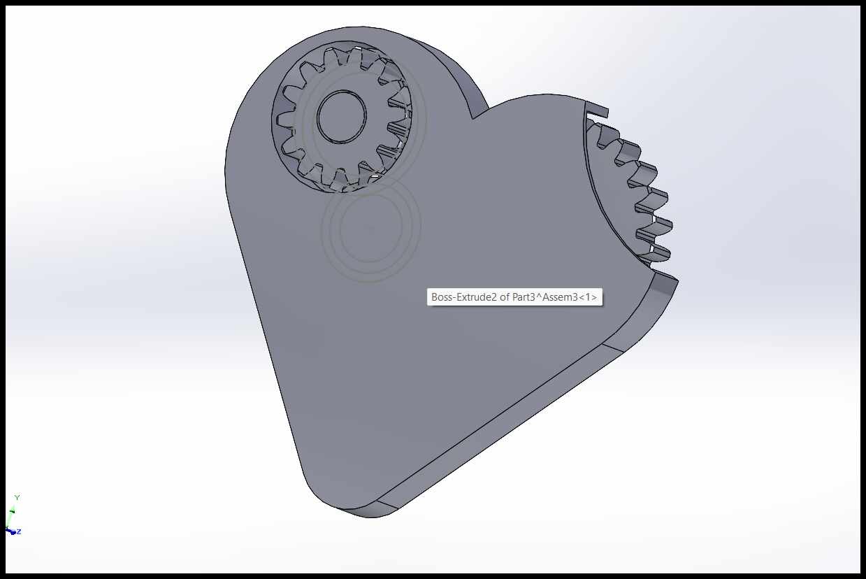
Building the 3D Model:
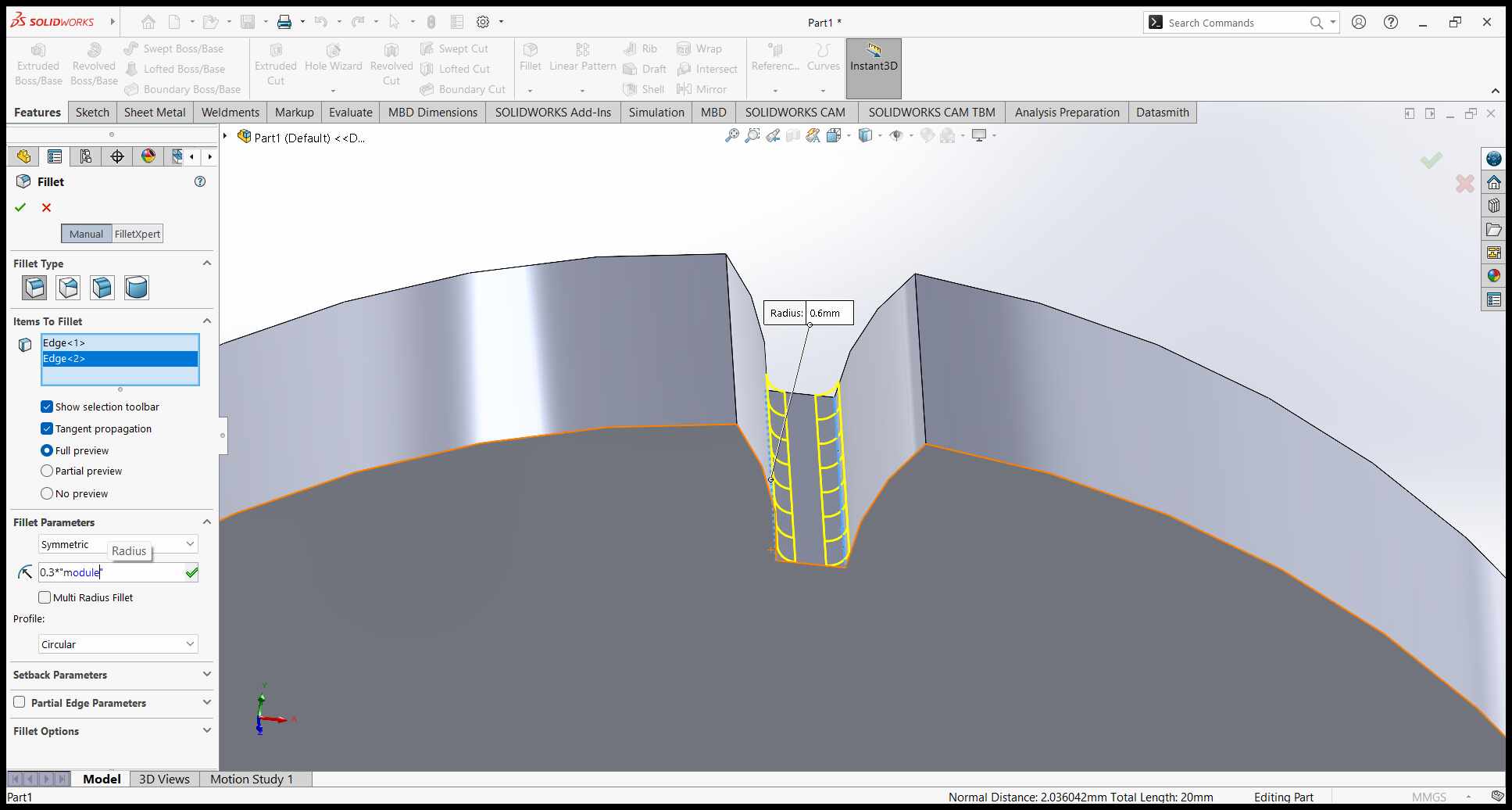
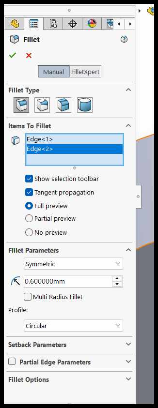
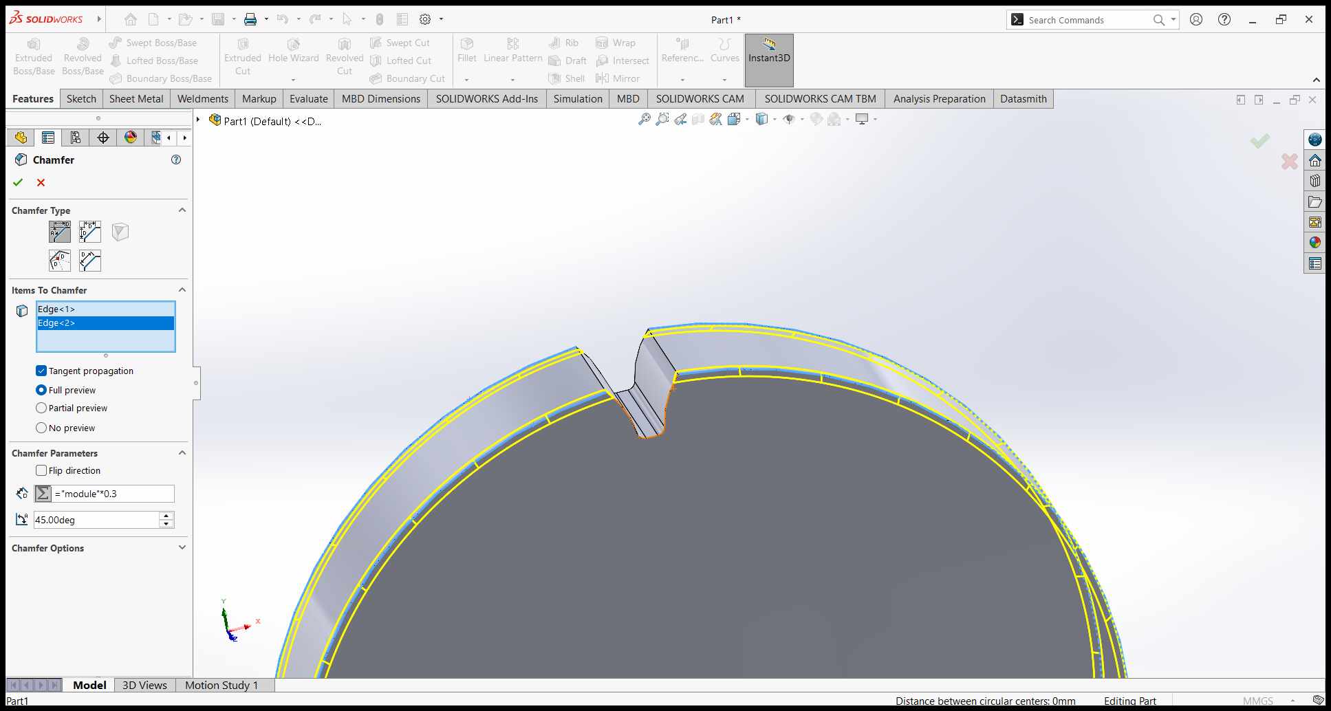
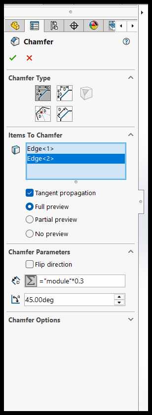
I used extrusion, lofting, and filleting tools to create the 3D shape of the heart. I ensured smooth transitions between surfaces to avoid overhangs that would require excessive support material during printing.
Exporting the Model:
Finally, I exported the model as an STL file, ensuring the resolution was high enough to capture all details. I also double-checked the file for errors using a mesh repair tool to ensure it was ready for 3D printing.
By following these steps and carefully considering the design constraints, I was able to create a functional mechanical heart that could be 3D printed in one piece with fully moving parts.
Failed Prints and Lessons Learned
During the process of 3D printing the mechanical heart, I encountered two failed prints before achieving a successful result. These failures provided valuable insights into the importance of print orientation and support placement.
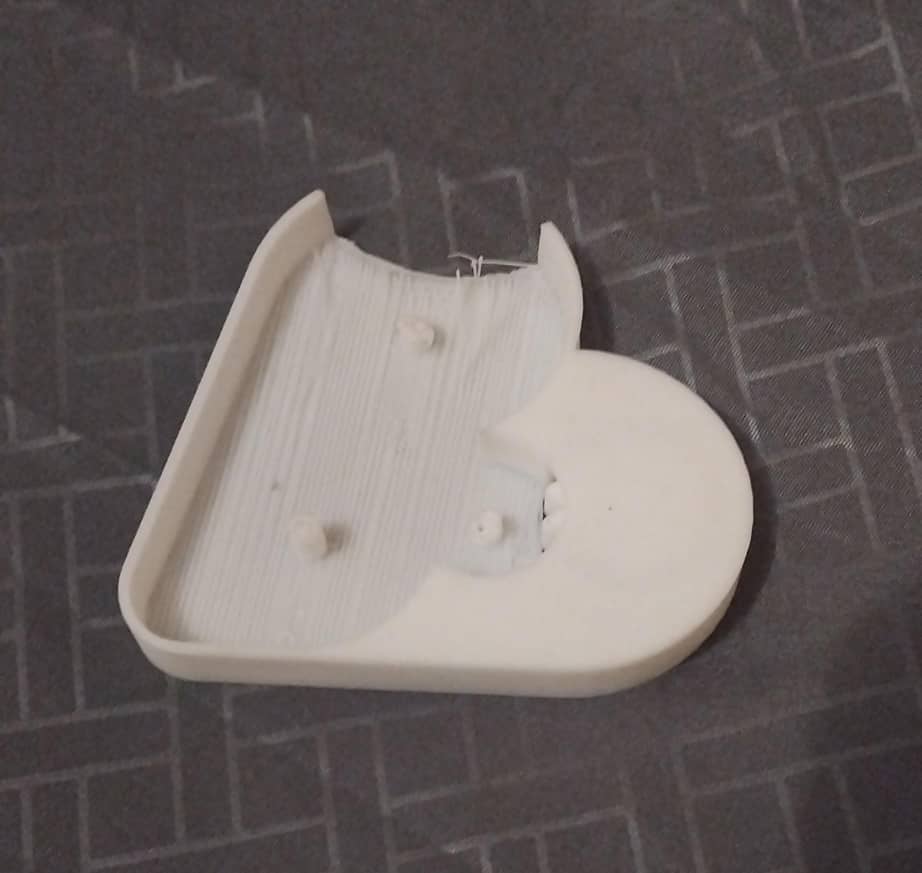
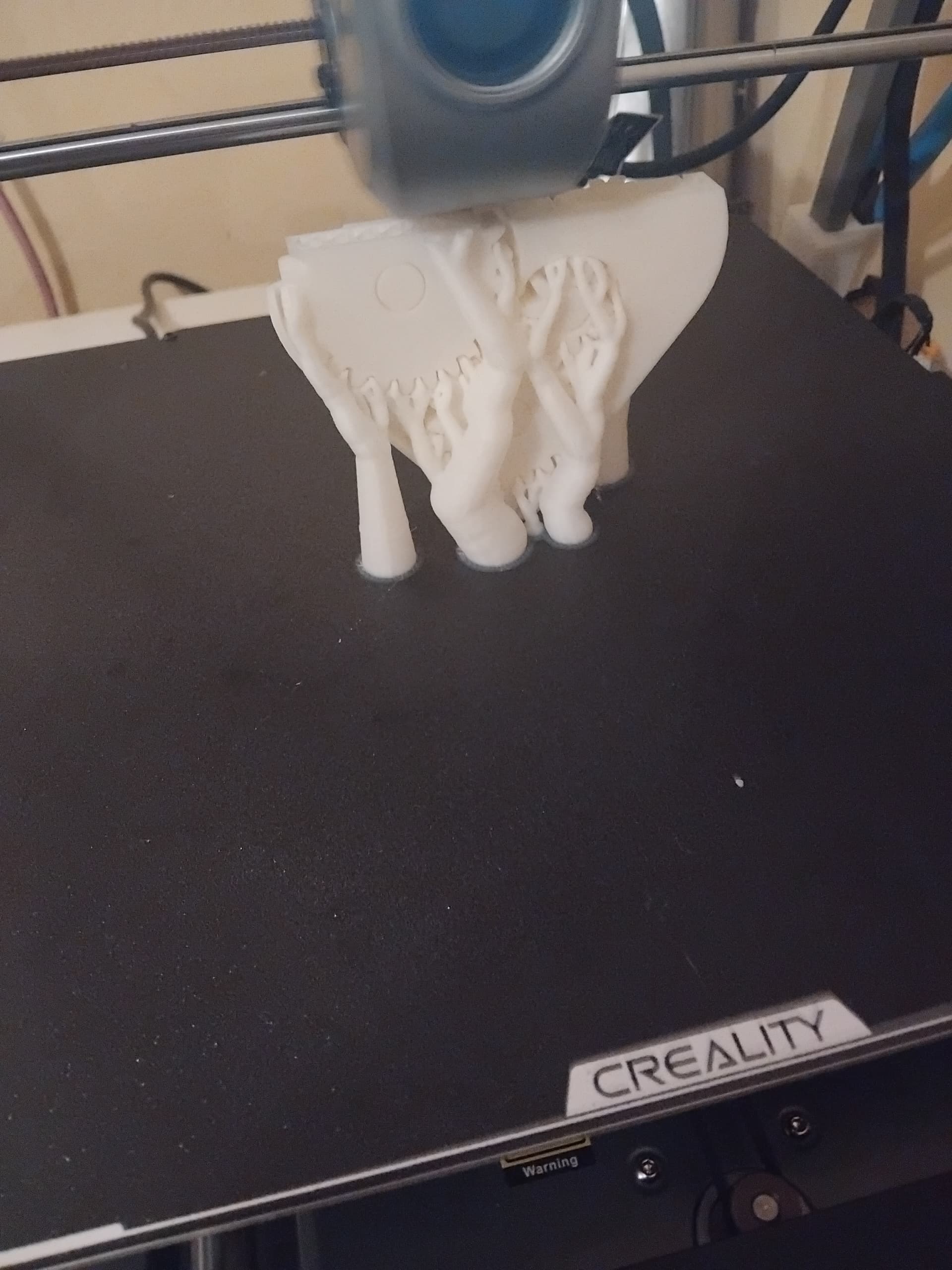
First failed print: The heart was oriented flat, leading to poor layer adhesion and warping.
Second failed print: Insufficient supports caused the overhangs to collapse.
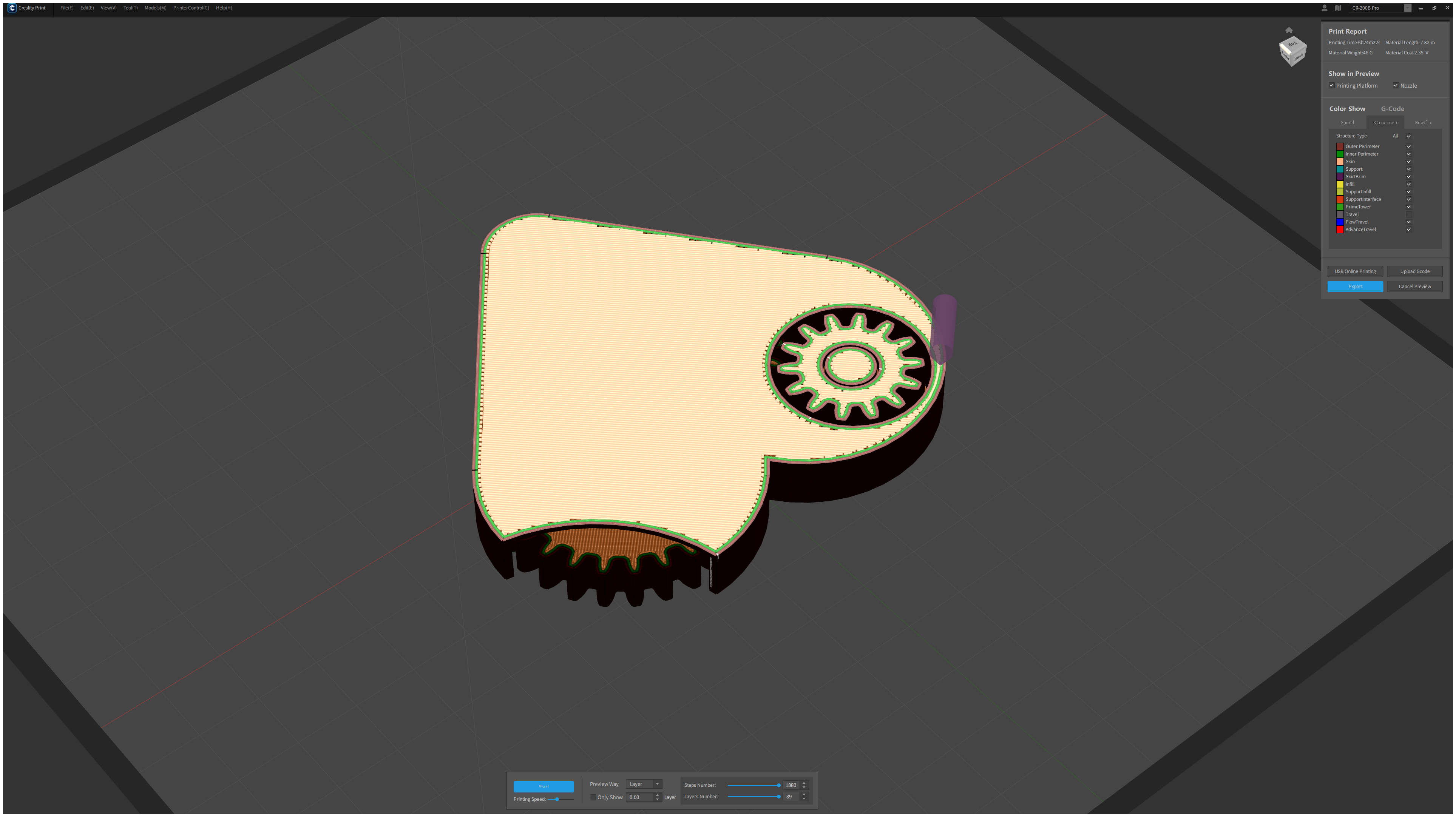
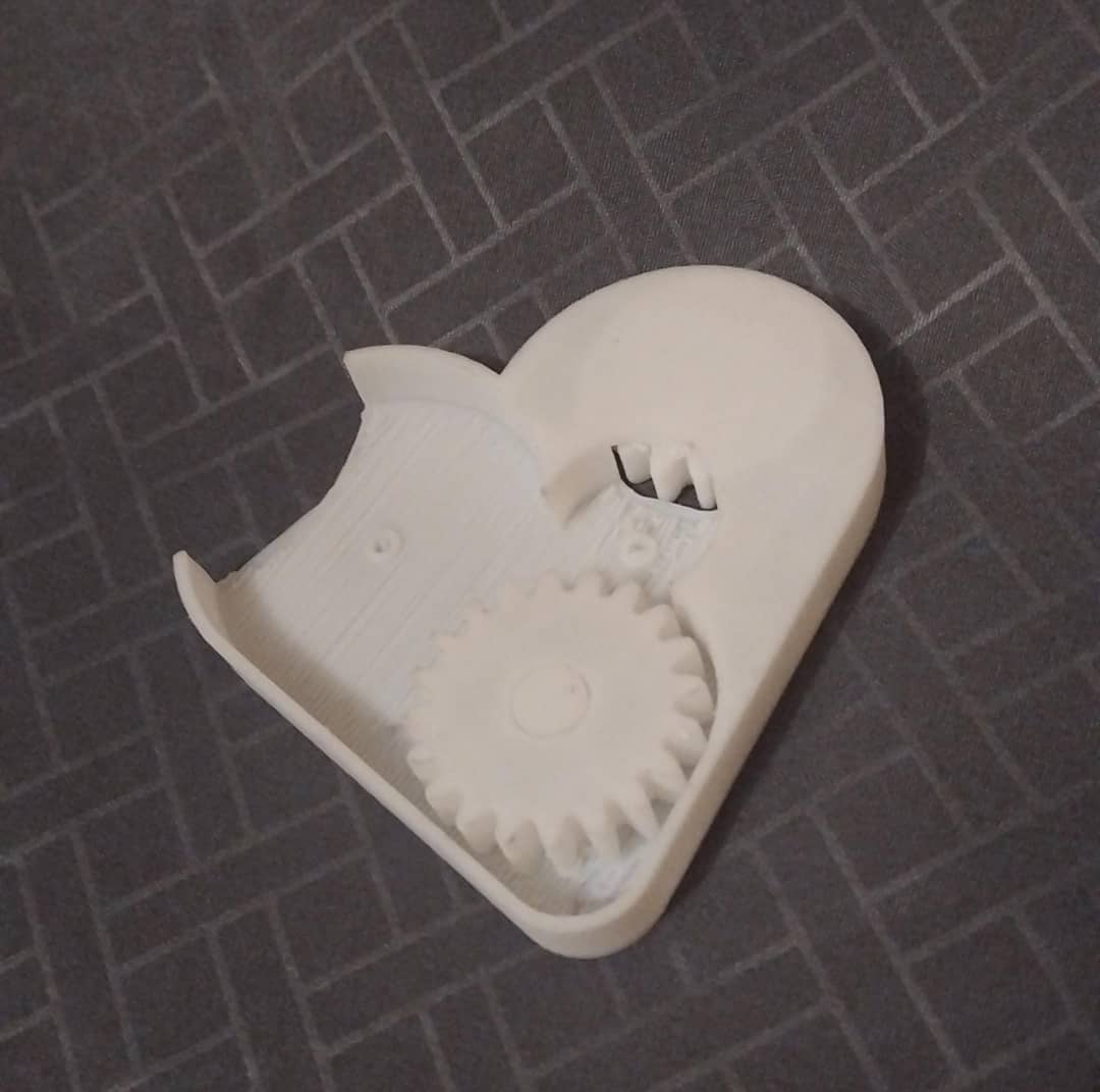
After analyzing the failures, I decided to change the orientation of the model and print the mechanical heart upright. This adjustment improved the support structure and layer bonding, resulting in a successful print with clean details and fully functional moving parts.
Successful print: The heart printed upright with excellent detail and movement.
Video demonstration of the finished mechanical heart with moving parts.
3D Scanning an Object Using Creality Scan
Below are the steps I followed to 3D scan an object using Creality Scan:
Preparing the Object:
I asked one of my colleagues to volunteer for a face scan. Since scanning a human face requires the subject to remain as still as possible, I explained the process and ensured they were comfortable. I also made sure their face was clean and free of reflective makeup or accessories, as shiny surfaces can interfere with scan accuracy.
The object prepared for 3D scanning using Creality Scan Ferret scanner.
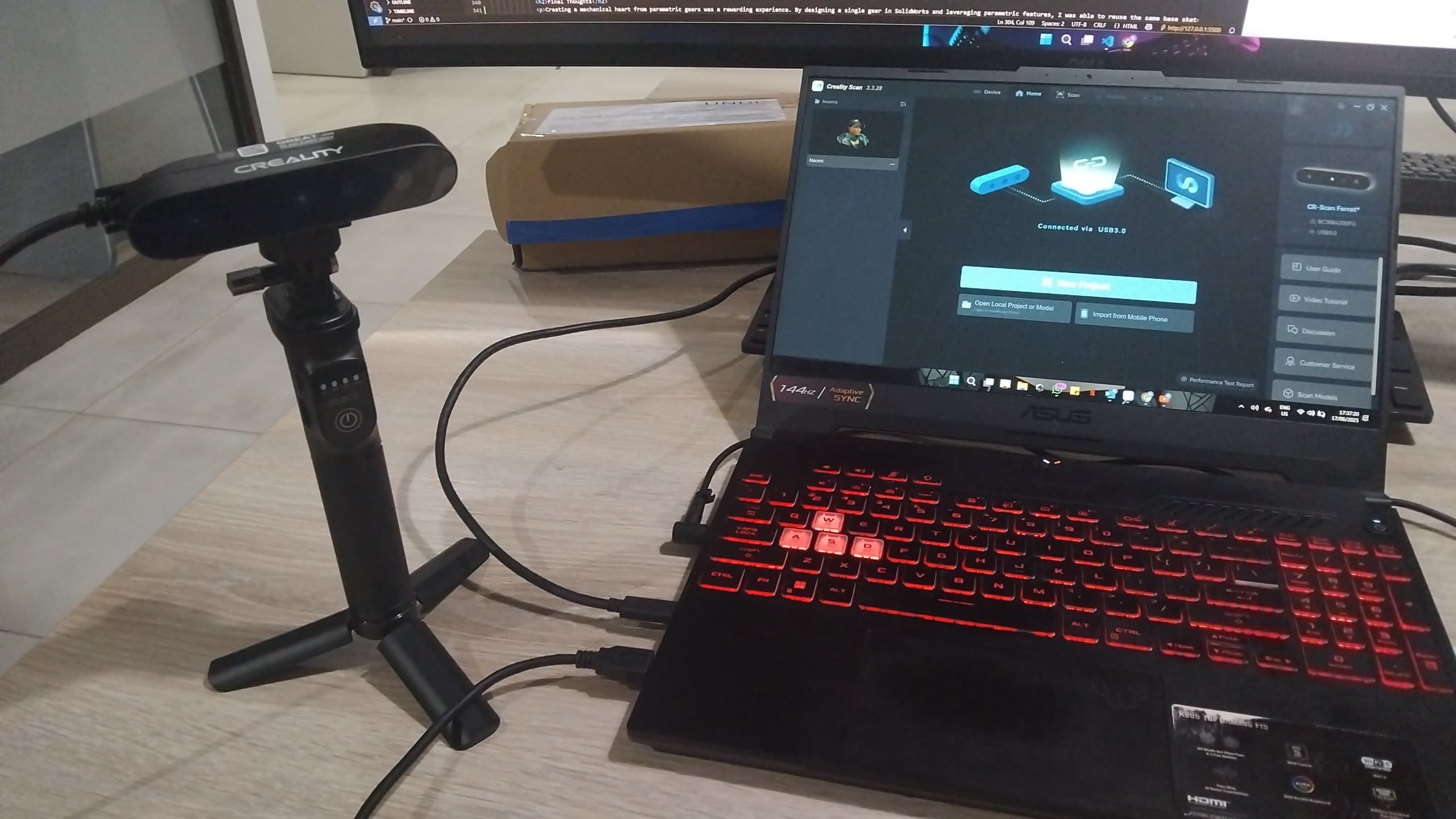
Setting Up the Scanner:
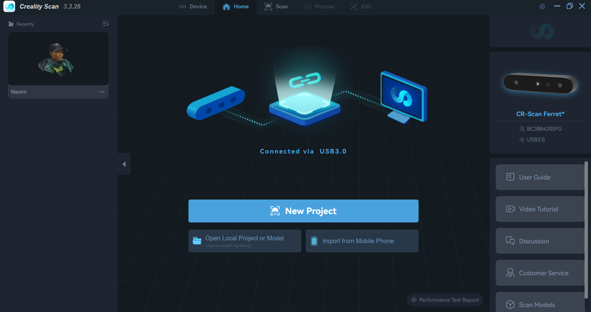
I connected the Creality scanner to my computer and installed the necessary drivers and Creality Scan software. For this scanner no callibaeration needed, ready to scan out the box.
Opened up creality scan and connected CR-Scan Ferret to the computer. Outo detected by software.
Positioning the Object:
I seated my volunteer on a rotating office chair to scan their face. Using a rotating chair allows the subject to remain still while I slowly turn the chair, enabling the scanner to capture all angles of the face without the volunteer moving their head. This helps maintain consistent positioning and reduces motion artifacts, resulting in a more accurate 3D scan.
The object prepared for 3D scanning using Creality Scan Ferret scanner.
Adjusting Scanner Settings:
First started a new scan
starting a new scan.
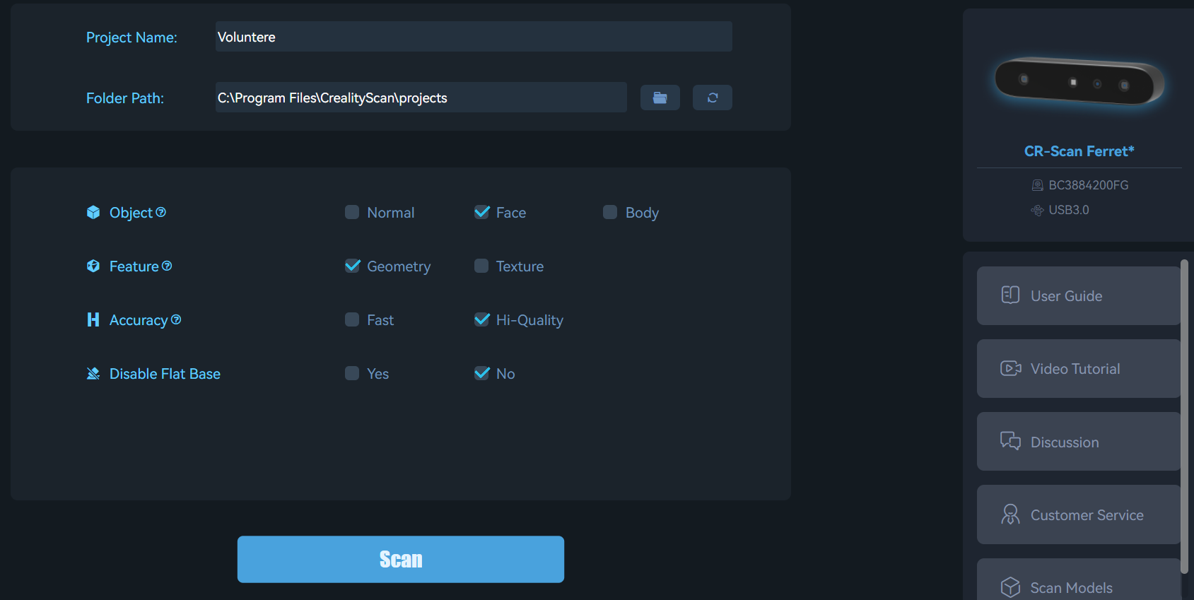
In the Creality Scan software, I adjusted the scanning settings, for object i selected Face, feature i selected geometry and accuracy was set to high-quality.
Adjustments.
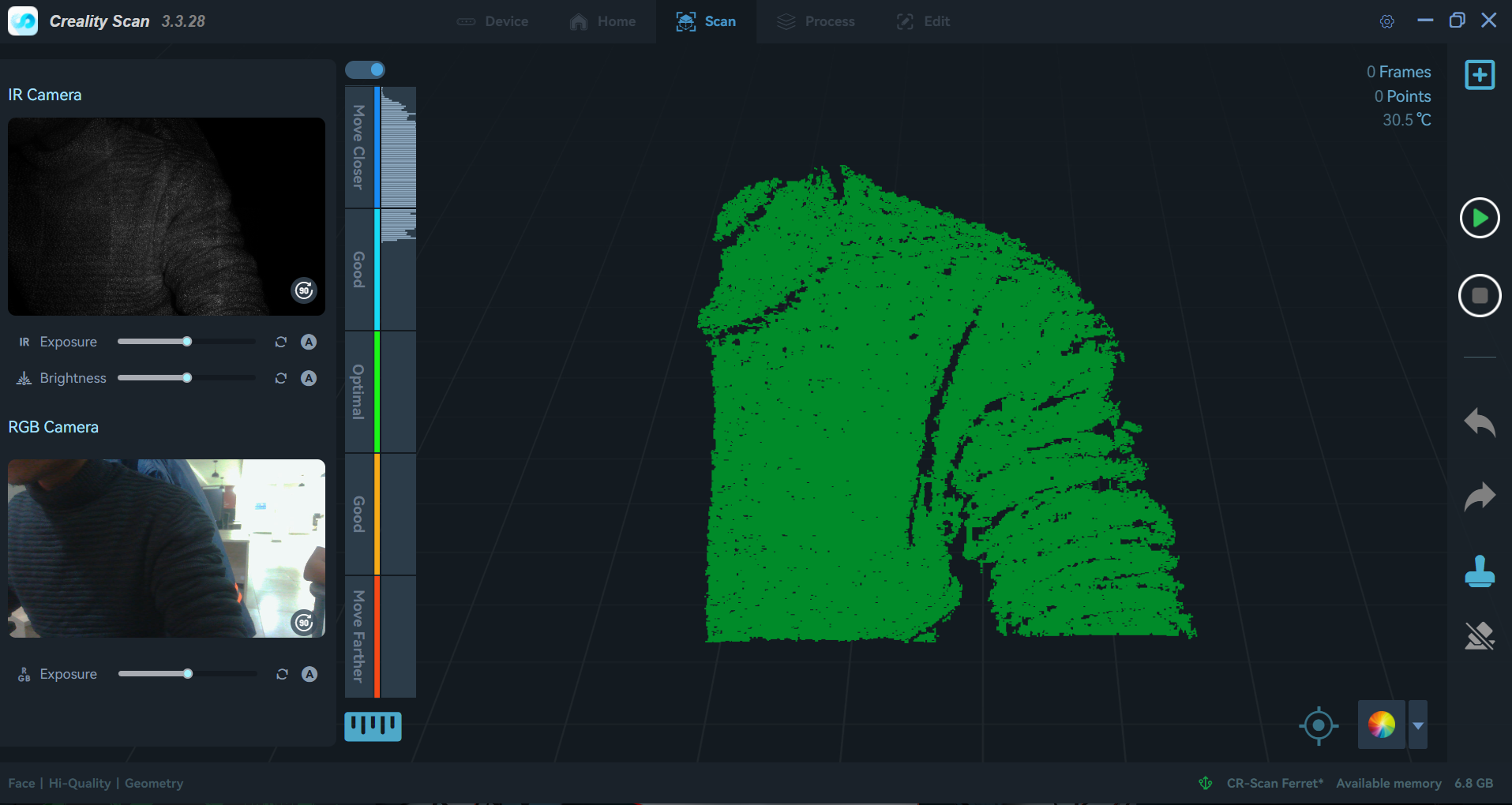
Starting the Scan:
I initiated the scanning process and monitored the progress in the software. The scanner captured multiple angles of the object as the turntable rotated. I ensured that the scanner maintained a consistent distance from the object for optimal results.
Starting the Scan
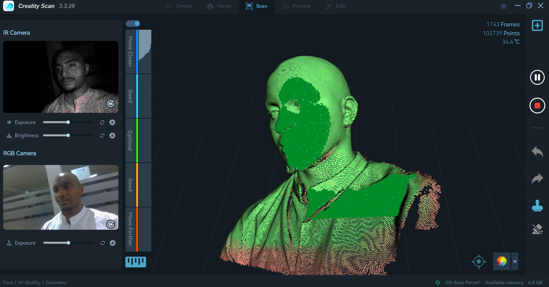
During scan
Video of the scanning process using the Creality Scan Ferret scanner.
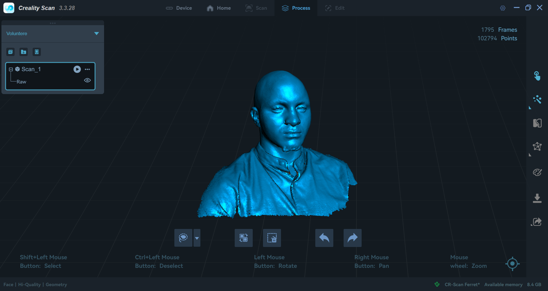
Post-Processing the Scan:
Once the scan was complete, I used the Creality Scan software to clean up the 3D model. This included removing noise, filling holes, and smoothing surfaces to create a watertight mesh.
Point cloud information after scanning.
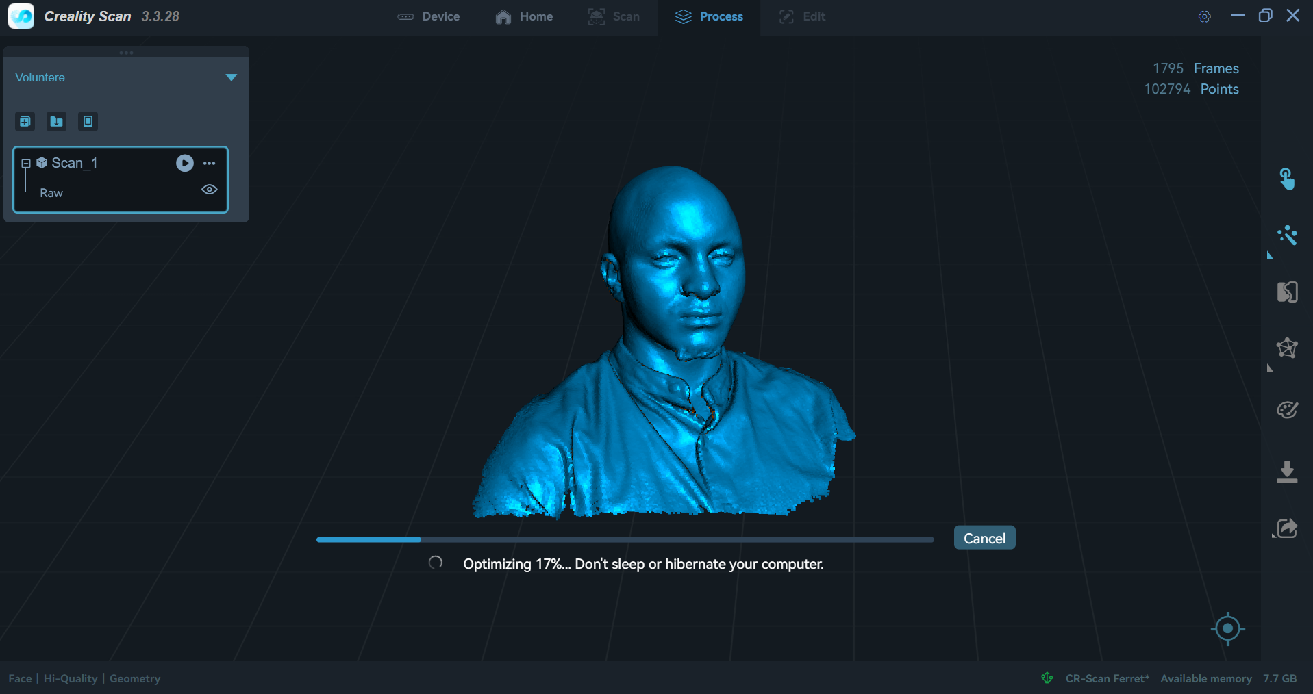
To begin the post processing i selected the One-Click Process button which does all the processing automatically.
Post-processing options in Creality Scan software started.
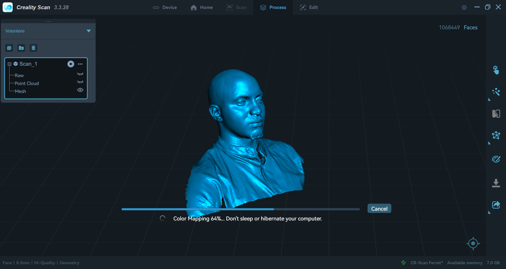
After optimizing the meshing operation started..
Immediately after, color mapping began.
Exporting the Model:
Finally, I exported the 3D model as an STL file for further use. The file was ready for 3D printing or additional editing in CAD software. I was only interested in the face scan so the shoulders can be edited out in blender or other software
Video showcasing the final 3D scan of the face using Creality Scan.
By following these steps, I successfully created a high-quality 3D scan of the object, which could be used for various applications such as 3D printing, animation character development, or digital archiving.
Final Thoughts
Creating a mechanical heart from parametric gears was a rewarding experience. By designing a single gear in SolidWorks and leveraging parametric features, I was able to reuse the same base sketch to generate multiple gears of different sizes and tooth counts. This approach saved significant time and ensured consistency throughout the design.
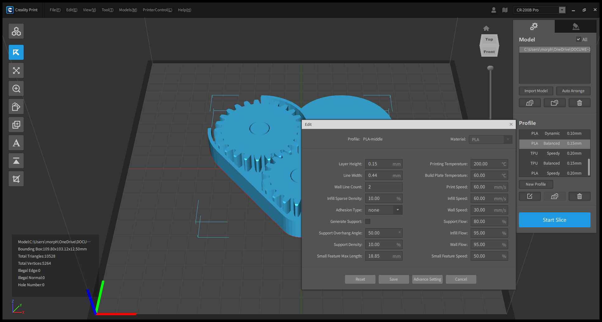
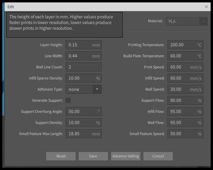
Through this project, I gained valuable insights into 3D printing, especially how adjusting print parameters like orientation, supports, and layer height can dramatically affect the final outcome. Experimenting with these settings helped me achieve a successful print with moving parts, and deepened my understanding of both CAD design and additive manufacturing processes.
Assignment Files
Download Assignment Files
You can download a ZIP archive containing the SolidWorks mechanical heart assembly, STL files, and the Creality 3MF print file below: