This week was all about learning embedded programming. Embedded programming involves writing software to control machines or devices that are not typically thought of as computers. These devices, known as embedded systems, can range from small gadgets like digital watches and MP3 players to large systems like industrial robots and avionics. The software written for these systems is usually highly specialized and optimized to perform specific tasks efficiently and reliably.
For this week, I was tasked with programming a board to do something, and I chose to program a Raspberry Pi Pico W to control an LED. The Raspberry Pi Pico W is a low-cost, high-performance microcontroller board with flexible digital interfaces. It features the RP2040 microcontroller chip, which includes a dual-core ARM Cortex-M0+ processor, 264KB of SRAM, and 2MB of flash memory. It also has built-in Wi-Fi, making it ideal for IoT projects.
Before I explored the features of the Raspberry Pi Pico W, there was a group assignment where we had to demonstrate and compare the toolchains and development workflows for available embedded architectures. This exercise provided a comprehensive understanding of different embedded systems and their respective development environments, which was crucial in selecting the right tools and methods for our individual projects.
Group Assignment
For the group assignment, we were tasked with demonstrating and comparing the toolchains and development workflows for available embedded architectures. This exercise provided a comprehensive understanding of different embedded systems and their respective development environments, which was crucial in selecting the right tools and methods for our individual projects.
A toolchain is a set of software tools used to compile, build, and debug software for a specific platform or architecture. It typically includes a compiler, linker, debugger, and other utilities that help developers write, test, and deploy code for embedded systems.
-
Compiler
A compiler is a program that translates source code written in a high-level programming language into machine code that can be executed by a computer's processor. It checks the code for errors and optimizes it for performance.
-
Linker
A linker is a tool that combines multiple object files generated by the compiler into a single executable file. It resolves references between different parts of the program and ensures that all necessary code and data are included in the final executable.
-
Building
Building is the process of compiling and linking source code to create an executable program. It typically involves several steps, including preprocessing, compiling, assembling, and linking, to transform the source code into a runnable application.
-
Debugging
Debugging is the process of identifying and fixing errors or bugs in a program. It involves running the program in a controlled environment, monitoring its behavior, and using tools like debuggers to inspect the code, variables, and memory to find and resolve issues.
Our group decided to explore the development environments for the following embedded architectures:
- Arduino
- Raspberry Pi pico w
- ESP32
The full group work can be found here.
Individual Assignment
For the individual assignment, I programmed a Raspberry Pi Pico W to control an LED. The Raspberry Pi Pico W is a low-cost, high-performance microcontroller board with flexible digital interfaces. It features the RP2040 microcontroller chip, which includes a dual-core ARM Cortex-M0+ processor, 264KB of SRAM, and 2MB of flash memory. It also has built-in Wi-Fi, making it ideal for IoT projects.
-
Raspberry Pi Pico W:
Imagine a tiny computer that can fit in your hand. It's like a mini-brain that can control other gadgets.
-
Microcontroller board:
Think of it as a small circuit board that can be programmed to do specific tasks, like turning on lights or moving robots.
-
Flexible digital interfaces:
This means it can connect to many different types of gadgets and sensors, like a universal plug.
-
RP2040 microcontroller chip:
This is the brain of the Raspberry Pi Pico W. It helps it think and process information.
-
Dual-core ARM Cortex-M0+ processor:
Imagine having two brains working together to solve problems faster.
-
264KB of SRAM:
This is like the short-term memory of the board, where it stores information it needs right away.
-
2MB of flash memory:
This is like the long-term memory, where it keeps important information even when it's turned off.
-
Built-in Wi-Fi:
This allows the board to connect to the internet without needing any extra parts, like having a built-in walkie-talkie.
-
Ideal for IoT projects:
IoT stands for Internet of Things. It means you can use this board to create smart gadgets that talk to each other over the internet, like smart lights or a weather station.
I followed the steps outlined in the Adafruit guide to set up the Raspberry Pi Pico W and write a simple program to blink an LED. The guide provided detailed instructions on how to install the necessary software, set up the development environment, and write the code. I connected an LED to the GPIO pin of the Raspberry Pi Pico W and uploaded the program to the board.
After successfully blinking the LED, I experimented with different patterns and timings to create a more complex light show. I also explored the capabilities of the RP2040 microcontroller chip and learned how to use the built-in Wi-Fi to connect the Raspberry Pi Pico W to the internet.
So What Exactly Did I Do?
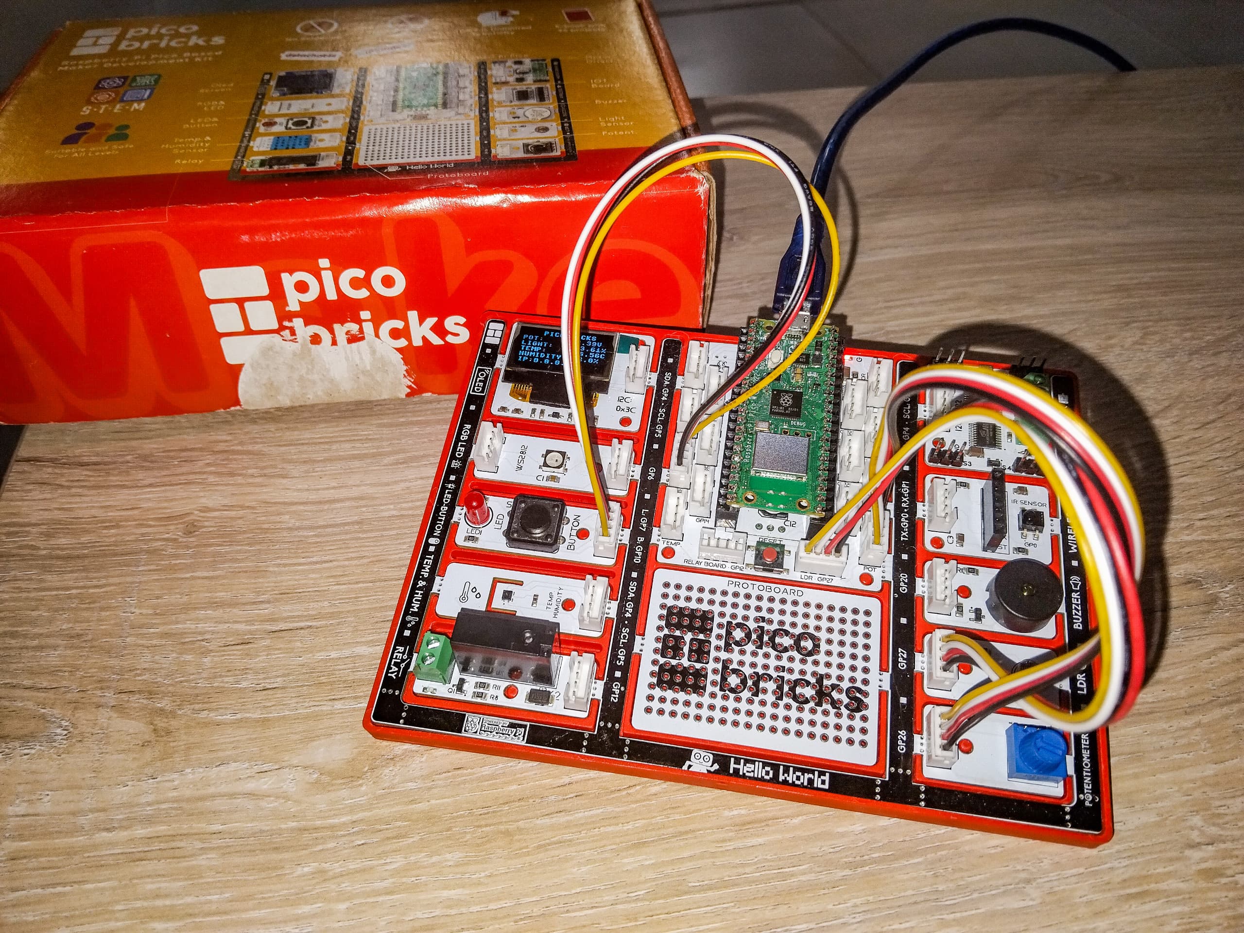
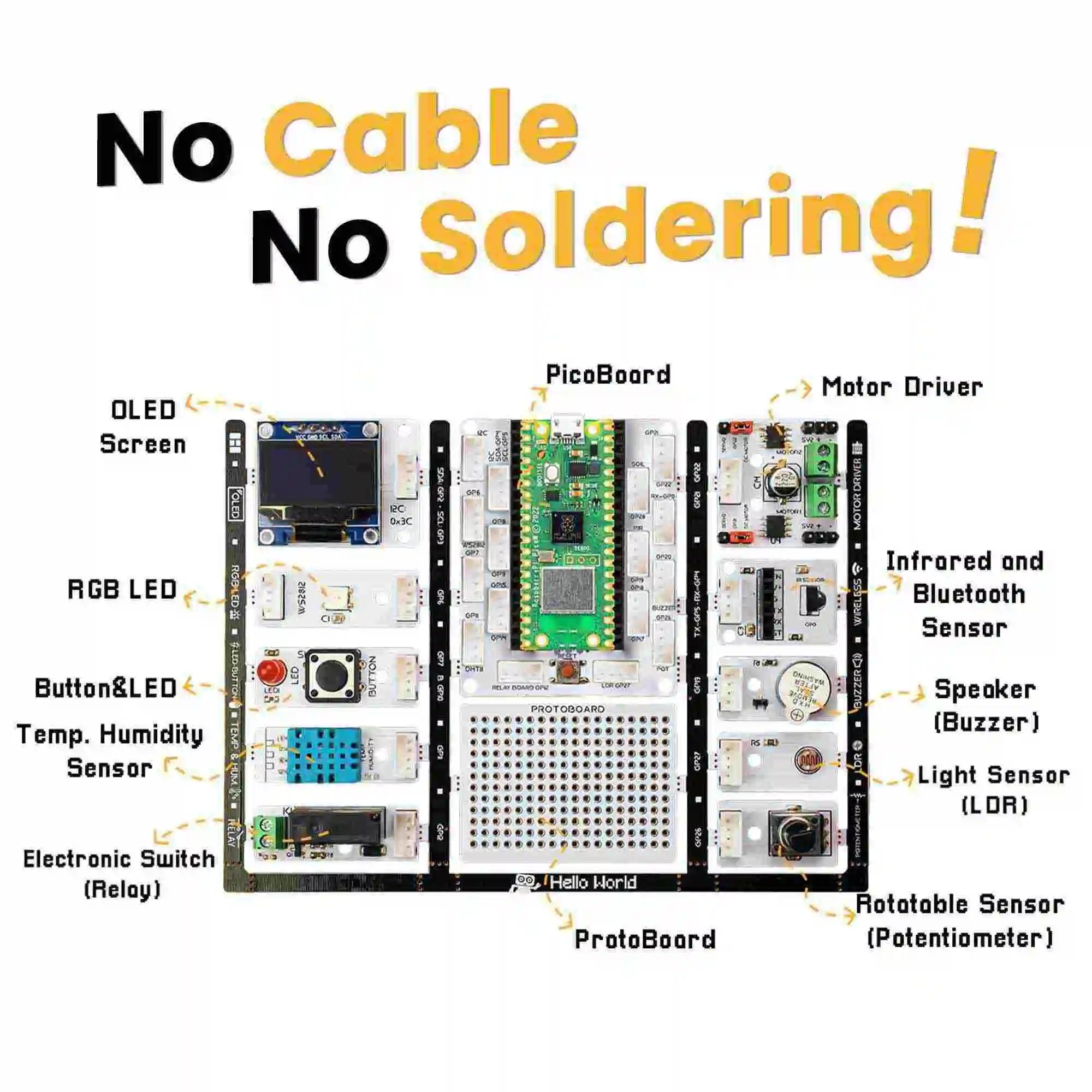
Luckily, in my FabLab, we had a Pico Bricks kit available. The Pico Bricks kit is an educational development platform designed to simplify the process of learning and prototyping with the Raspberry Pi Pico.
It includes various modules and components such as LEDs, sensors, buttons, and displays, all integrated into a single board. This made it easier for me to quickly set up and experiment with different projects without needing to connect multiple external components. I used the Pico Bricks kit to create a simple project where an LED would blink in response to a button press. This hands-on experience helped me understand the basics of embedded programming and the capabilities of the Raspberry Pi Pico W.
Bellow is the board labeled: image source picobricks.com
Bellow is the steps I followed:
-
Finding The Datasheet.
First things first, I needed to understand the device I was programming and how to program it. The kit came with a manual that explained that the Raspberry Pi Pico W is programmed using MicroPython.
MicroPython is a lean and efficient implementation of the Python 3 programming language that is optimized to run on microcontrollers and in constrained environments. I found more detailed information about MicroPython on the official website, micropython.org.
Okay so now I know what MicroPython is, now I need to understand what the pico is and what it is capable of. Through the datasheet located at Raspberry Pi Pico W Datasheet, I was able to understand how to write code for the Pico and how to power it correctly. The datasheet can be browsed bellow:
-
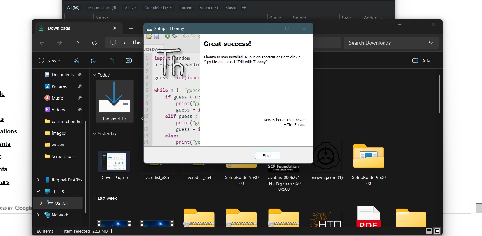
Installing The Required Software.
Before I could start programming the Raspberry Pi Pico W, I needed to install the necessary software on my computer. This included the Thonny IDE, which is a Python Integrated Development Environment (IDE) that makes it easy to write, run, and debug Python code. I also installed the CircuitPython firmware for the Raspberry Pi Pico W, which provides a high-level interface for interacting with the board's hardware.
-
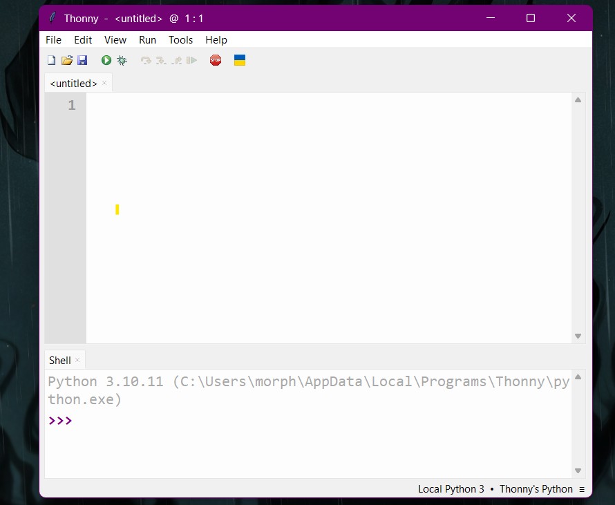
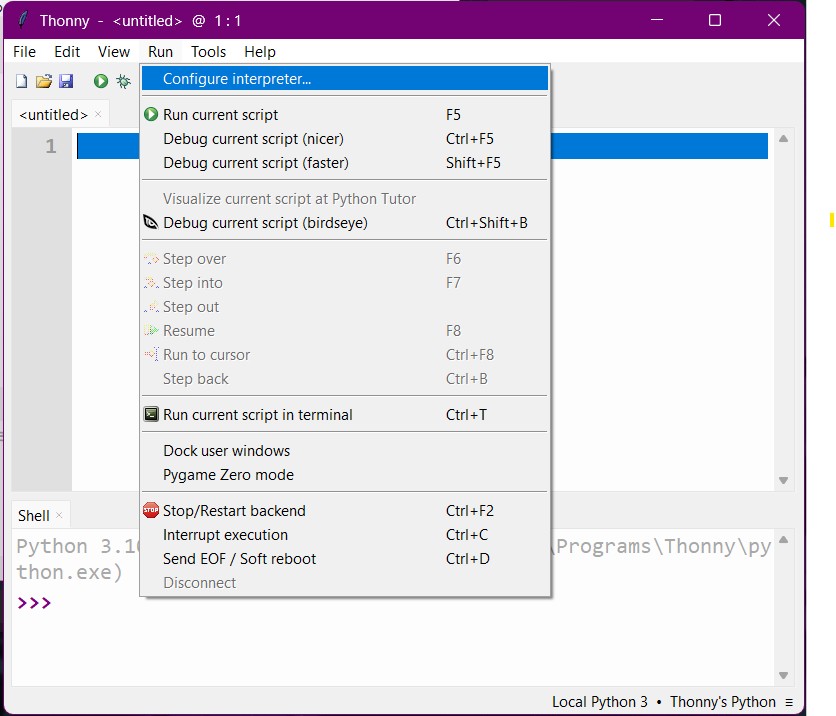
Configuring Thonny
Once Thonny was installed, I launched it and continued with the setup.
Next went to Run > Configure Interpreter..
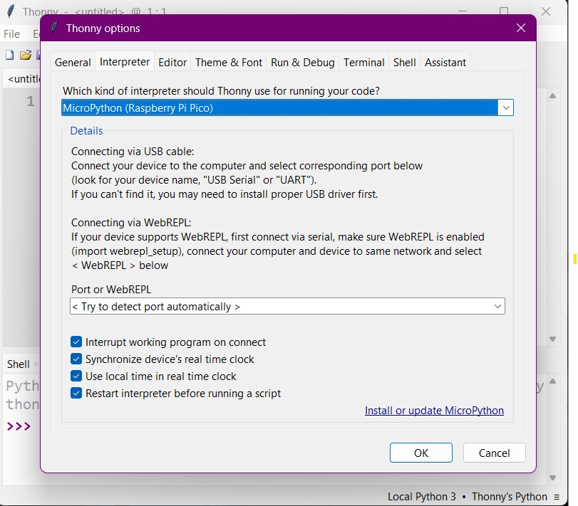
Then I selected MicroPython (Raspberry Pi Pico) from the list of interpreters.
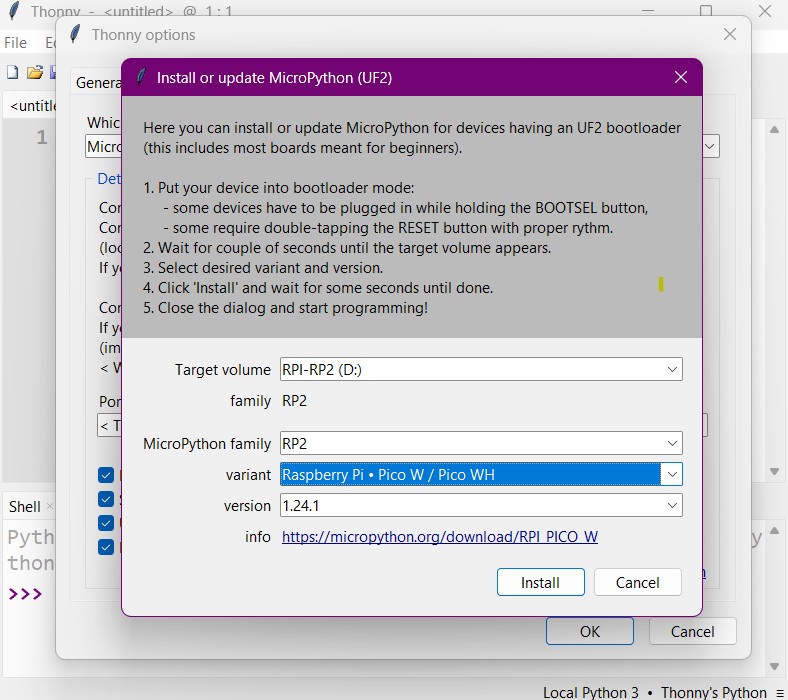
Next I clicked on Install or update MicroPython. A little window popped up with instructions that I then followed to the t.
After the installation was complete, I clicked on OK and then OK again to close the interpreter configuration window.
-
Writing Code and Figuring Out the Circuit(Wokwi Simulation).
Before diving headfirst into the world of embedded programming, I decided to take a detour through the magical land of Wokwi.
Here, I could simulate my Raspberry Pi Pico W adventures without the fear of frying any actual hardware. I spent some time tinkering with virtual LEDs and buttons, and it was like playing a video game where the high score was knowledge.
Simulating first is like having a dress rehearsal before the big show; it helps you catch all the little mistakes and understand the code better without any real-world consequences. Plus, it's a lot cheaper than buying new components every time you make a mistake!
- First, I went to the Wokwi website and created an account.
-
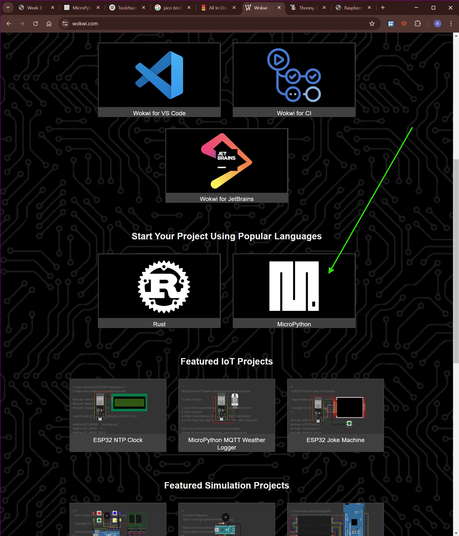
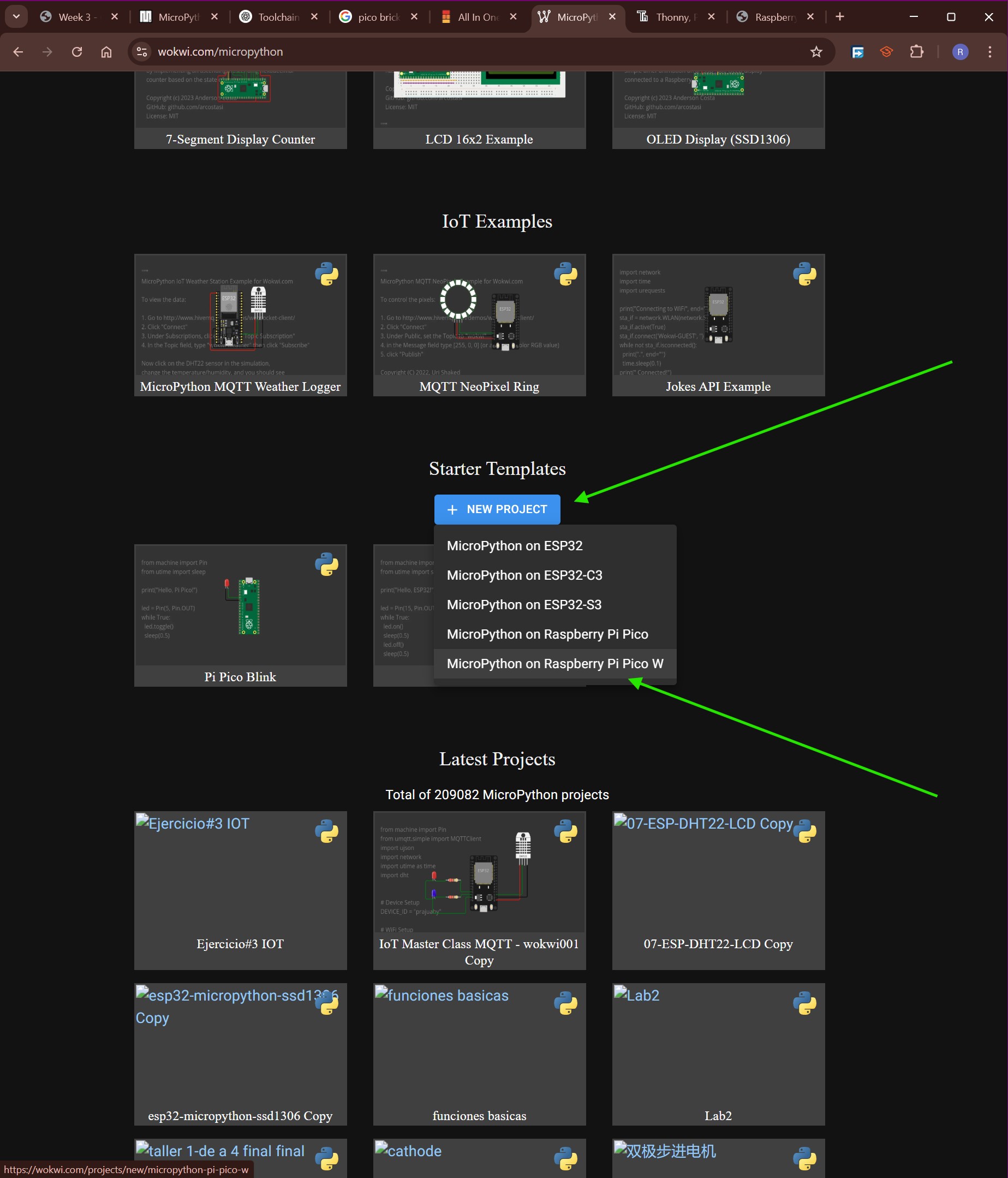
Next, form the wokwi home page I scrolled down and started a new project in MicroPython.
I clicked on the New Project button and selected the Raspberry Pi Pico W board from the list of available boards.
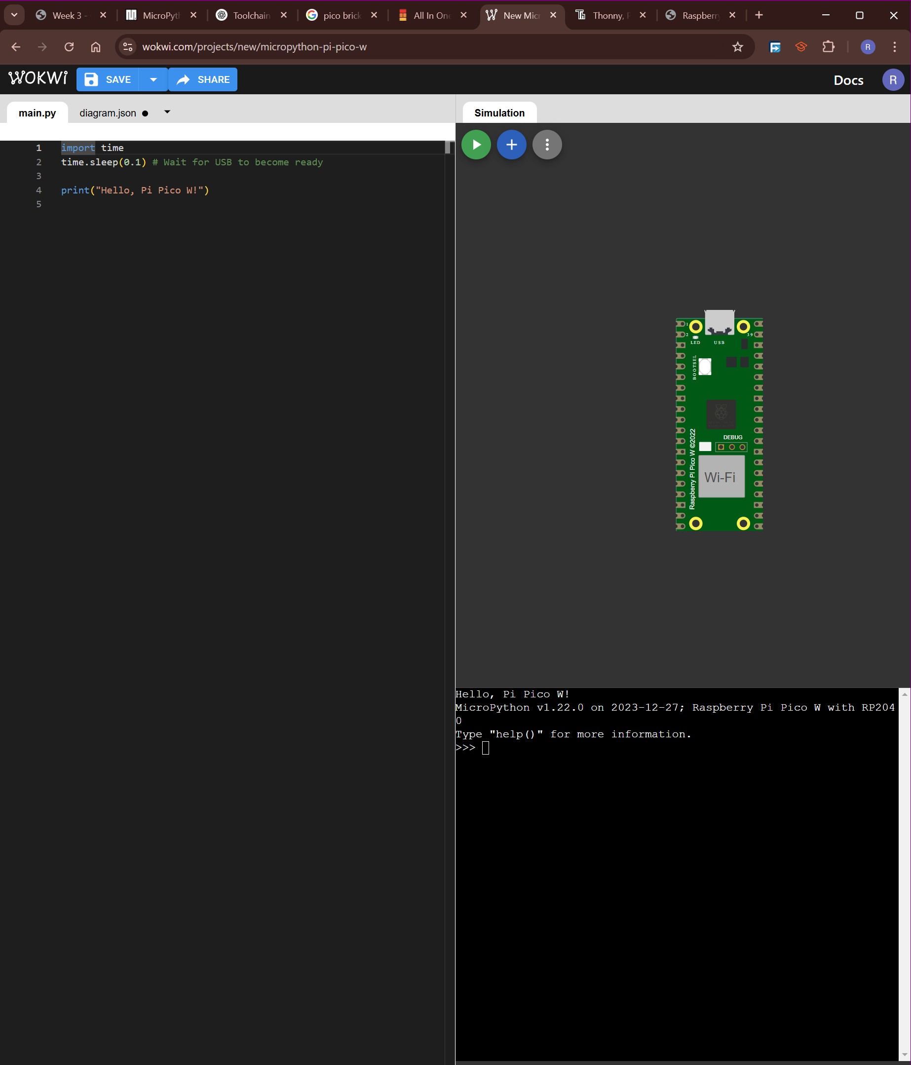
Bellow is the window that I went to next:
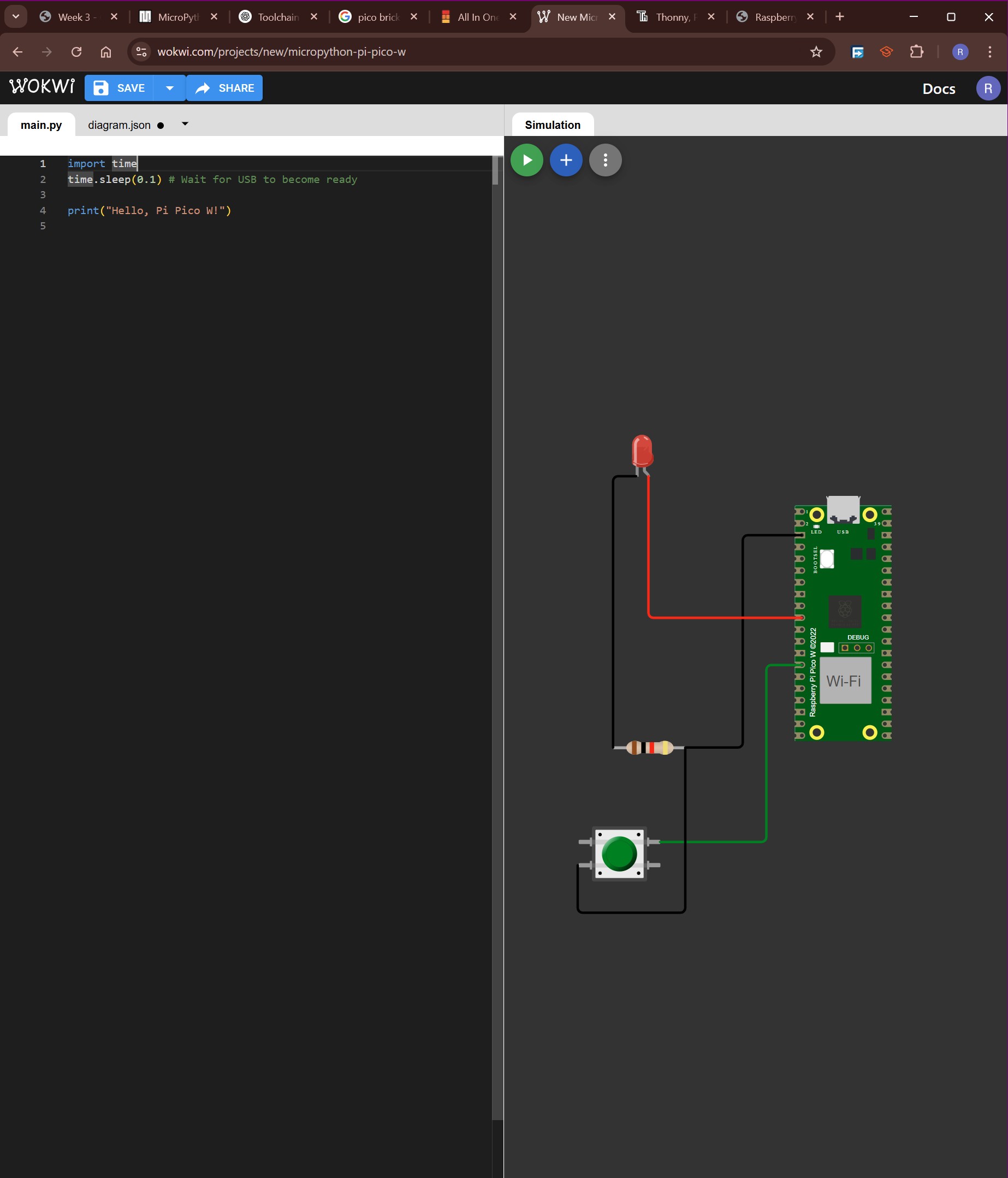
- Then I added an LED and a button to the circuit by dragging and dropping them from the components panel.
- I connected the LED to GPIO pin 7 and the button to GPIO pin 10. I connected them this way because on the pic bricks module, the button and switch are connected the same way. As shown bellow:
- Finally, I wrote a simple Python script to blink the LED when the button was pressed. The code is shown below:
from machine import Pin
import time

# Define LED and button pins
led = Pin(7, Pin.OUT)      # LED connected to GPIO 7
button = Pin(10, Pin.IN, Pin.PULL_UP)  # Button connected to GPIO 10 with internal pull-up resistor

while True:
    if not button.value():  # Button is pressed (LOW)
        led.on()            # Turn LED on
        time.sleep(0.5)     # Keep LED on for 500ms
        led.off()           # Turn LED off
        time.sleep(0.5)     # Delay before next check
-
Writing The Code (Thonny).
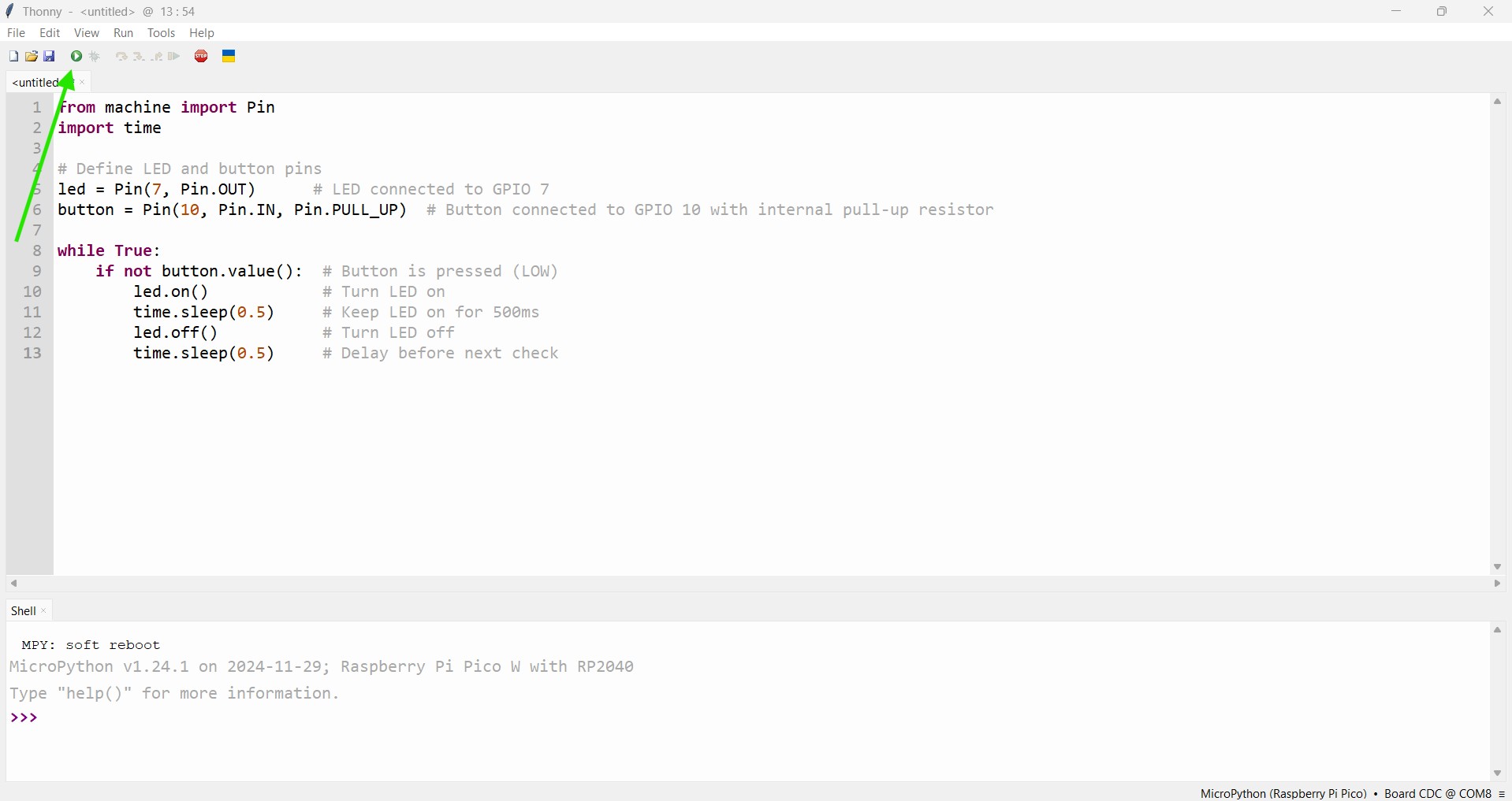
After successfully simulating the circuit on Wokwi, I was ready to write my first program for the actual Raspberry Pi Pico W. I opened a new file in Thonny and wrote a simple Python script to blink an LED connected to the board. The code is shown below:
Well actually, I just copied the code i wrote from Wokwi,I was curious to see if it will work unchanged.
After writing the code, I saved the file and clicked on the Run button to upload it to the Raspberry Pi Pico W.
Bellow is the image of the code in Thonny:
Alright, so the upload worked, but something was off. My program was working in the opposite way. Pressing the button was supposed to make the LED blink, but in my case, the LED was blinking by default and pressing the button turned it off.
The good thing is that I am experienced enough in electronics to know this means the circuit is slightly different. The button could possibly be pulling the GPIO pin high when pressed, which would in turn require the GPIO pin to have its internal pull-down resistor activated instead of the pull-up.
Only one way to find out...
The simplest solution is to alter the code instead of the circuit...
  # the plan is to change the if statement
  # by removing 'not', this will efectively flip the behaviour of the button
  if not button.value():  # original from wokwi

  if button.value():  # altred to work with the pico brick kit
After making the changes, I saved the file and uploaded it to the Raspberry Pi Pico W. This time, the LED blinked when the button was pressed, just as I had intended.
Below is the video of the final working circuit:
As someone who has experience programming embedded systems with C++, transitioning to Python for embedded systems has been an interesting journey. Initially, I was curious about how Python would compare to C++ in terms of performance and ease of use. The step-by-step guides and simulations provided a smooth transition and a solid foundation. The hands-on approach with the Raspberry Pi Pico W and the Pico Bricks kit allowed me to see the immediate results of my code, which was incredibly motivating. Each success, from blinking an LED to creating more complex interactions, has broadened my perspective and deepened my understanding of embedded programming. This journey has shown me the potential of Python in the world of embedded systems and has sparked a keen interest in exploring more advanced projects in the future.