Week 3 - Computer Controlled Cutting
This week, we are exploring the world of Computer Controlled Cutting. This is an exciting week where we get to learn about the different types of cutting machines and how they can be used to create intricate designs. We will be using a vinyl cutter to create stickers and a laser cutter to create a press-fit construction kit.
Group Assignment
This week's group assignment involves several important tasks. First, we need to complete our lab's safety training to ensure that we are familiar with all the necessary precautions and procedures. Next, we will characterize our lasercutter by examining its focus, power, speed, rate, kerf, joint clearance, and the different types of materials it can cut. Finally, we will document our findings on the group work page and reflect on what we learned on our individual pages. This will help us understand the capabilities and limitations of the lasercutter, and how to use it effectively and safely.
So, what did we do and what did I learn?
You can find the full documentation of our group work at the following link:
Group Assignment: Computer Controlled Cutting
Individual Assignment
For this week's individual assignment, we are tasked with designing, lasercutting, and documenting a parametric construction kit. The kit should account for the lasercutter kerf and be designed to be assembled in multiple ways without the need for glue or fasteners. Additionally, we will cut something on the vinyl cutter. We will document the design process, including the design files, the settings used for the laser cutter and vinyl cutter, and the final products.
Vinyl Cutting
For the vinyl cutting assignment, I decided to create a sticker of my logo. I figured I'd start with the vinyl cutter because, let's be honest, it's the easiest way to avoid setting anything on fire😂😂.
Steps to Design for Vinyl Cutting in Adobe Illustrator
-
Opening Adobe Illustrator:
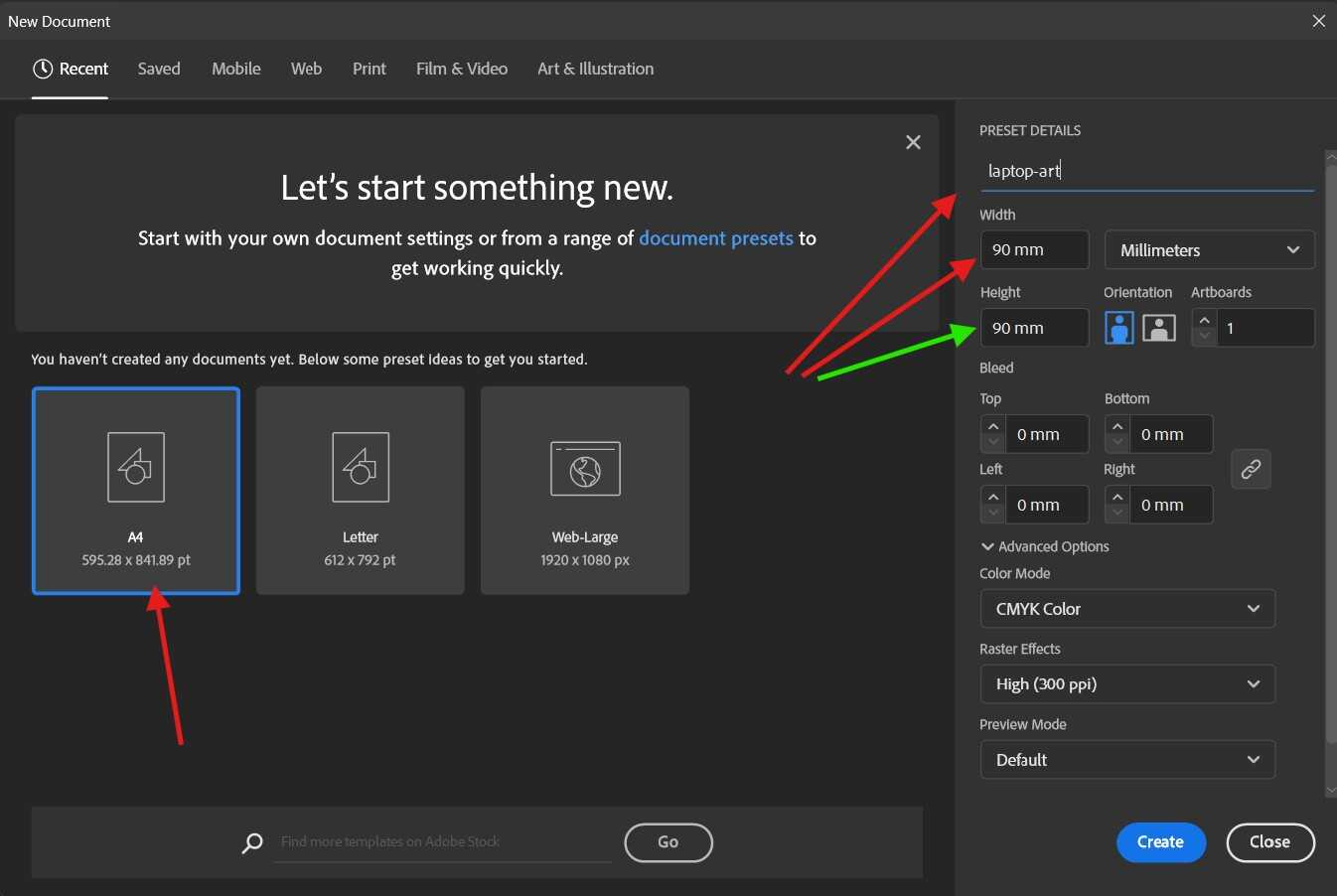
I launched Adobe Illustrator and created a new document with the desired dimensions for my design.
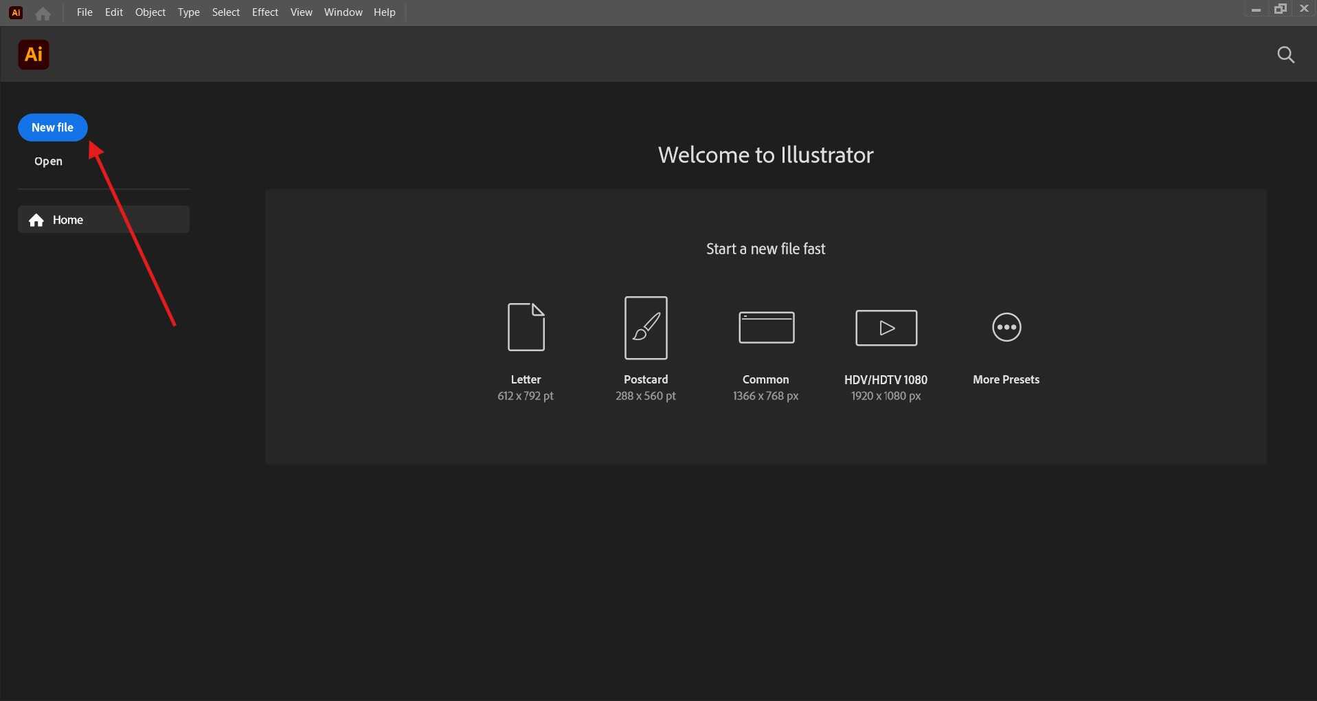
I had space on my laptop among other stickers and this space measured aproximately 90mm by 90mm. This is what I set my document size to
-
Creating My Design:
To start off this step, I went into Pngwing to look for a stock image to inspire my design. I already planned on looking for something that aligns with my love for electronics, so I found an image of a circuit. This image was then imported into Illustrator, where it was about to get a digital makeover worthy of a tech-savvy fairy godmother.
Bellow is the image I got from Pngwing:

Next step is to import the image into Illustrator and edit it by performimg image trace on the image.
What image trace does is that it converts the image into a vector image. This is important because the vinyl cutter cuts vector images. The image trace tool can be found under the window tab in Illustrator.
      What is a vector image?
      A vector image is a type of digital graphic that uses mathematical points to create an image. Unlike raster images, which are made up of pixels, vector images can be scaled to any size without losing quality. This makes them ideal for designs that need to be resized or edited frequently.

      So why do vinyl cutters use vector images?
      Vinyl cutters use vector images because they are made up of lines and curves that can be easily translated into cutting paths. This allows the cutter to follow the design precisely and create clean, sharp cuts.
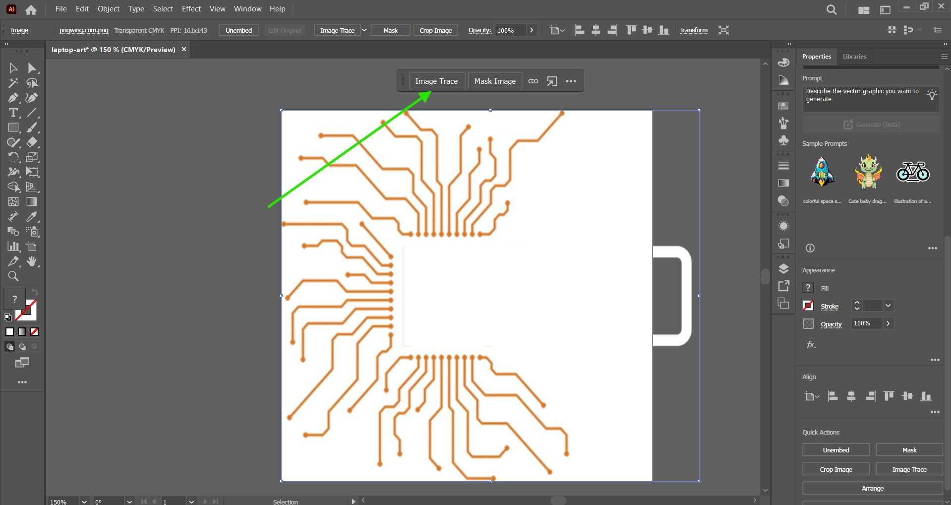
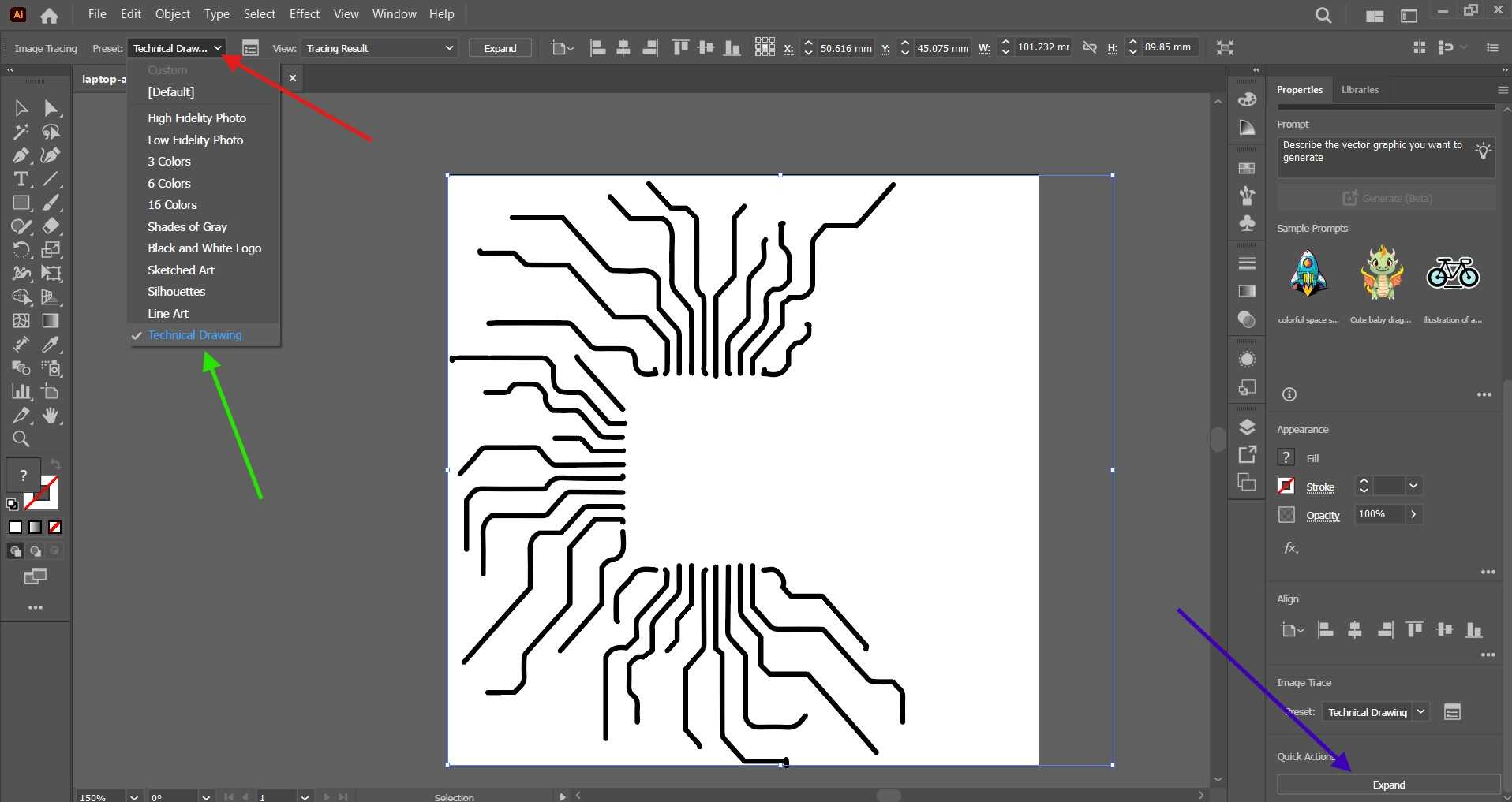
Image trace wa then set to technical
-
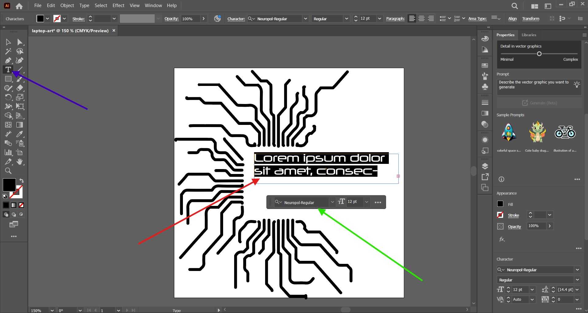
Add Text and Convert It to Outlines:
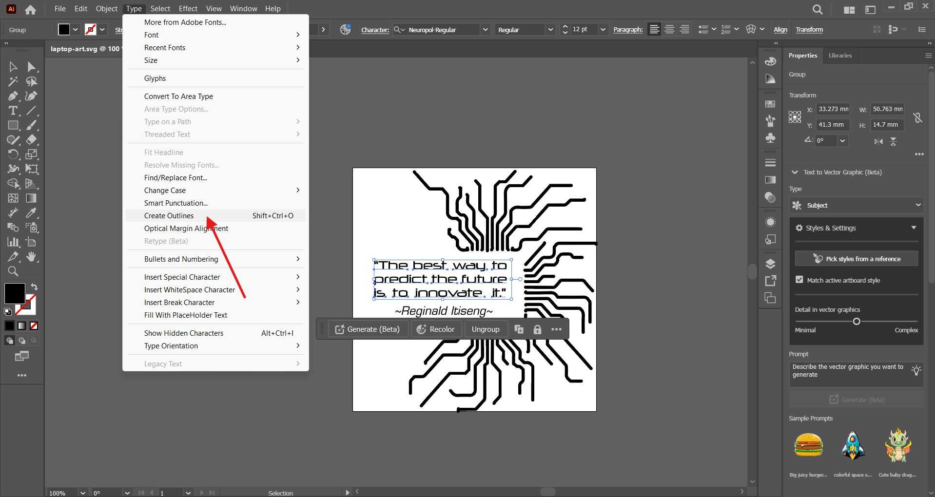
First, I added the text for my design by selecting the Text Tool and typing out the desired text. After positioning the text, I selected it and went to Type > Create Outlines to convert it to vector paths. This step is important because it ensures that the text will be cut accurately by the vinyl cutter, as the cutter can only follow vector paths and not font data.
Then the text was converted to outlines by clicking on Type > Create Outlines. This step ensures that the text is converted into vector paths, which the vinyl cutter can follow accurately.
-
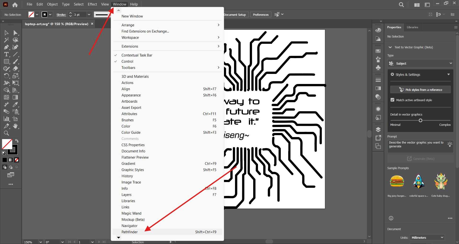
Check for Overlapping Paths:
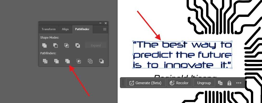
To ensure that there are no overlapping paths that could cause issues during cutting. I use the Pathfinder tool to merge or subtract paths as needed. To access the Pathfinder I went to window and found Pathfinder in the drop down menu.
After clicking on the pathfinder tool, I selected the merge option to merge the paths together. It is important to ensure the text is selected for this step to work❗❗❗
-
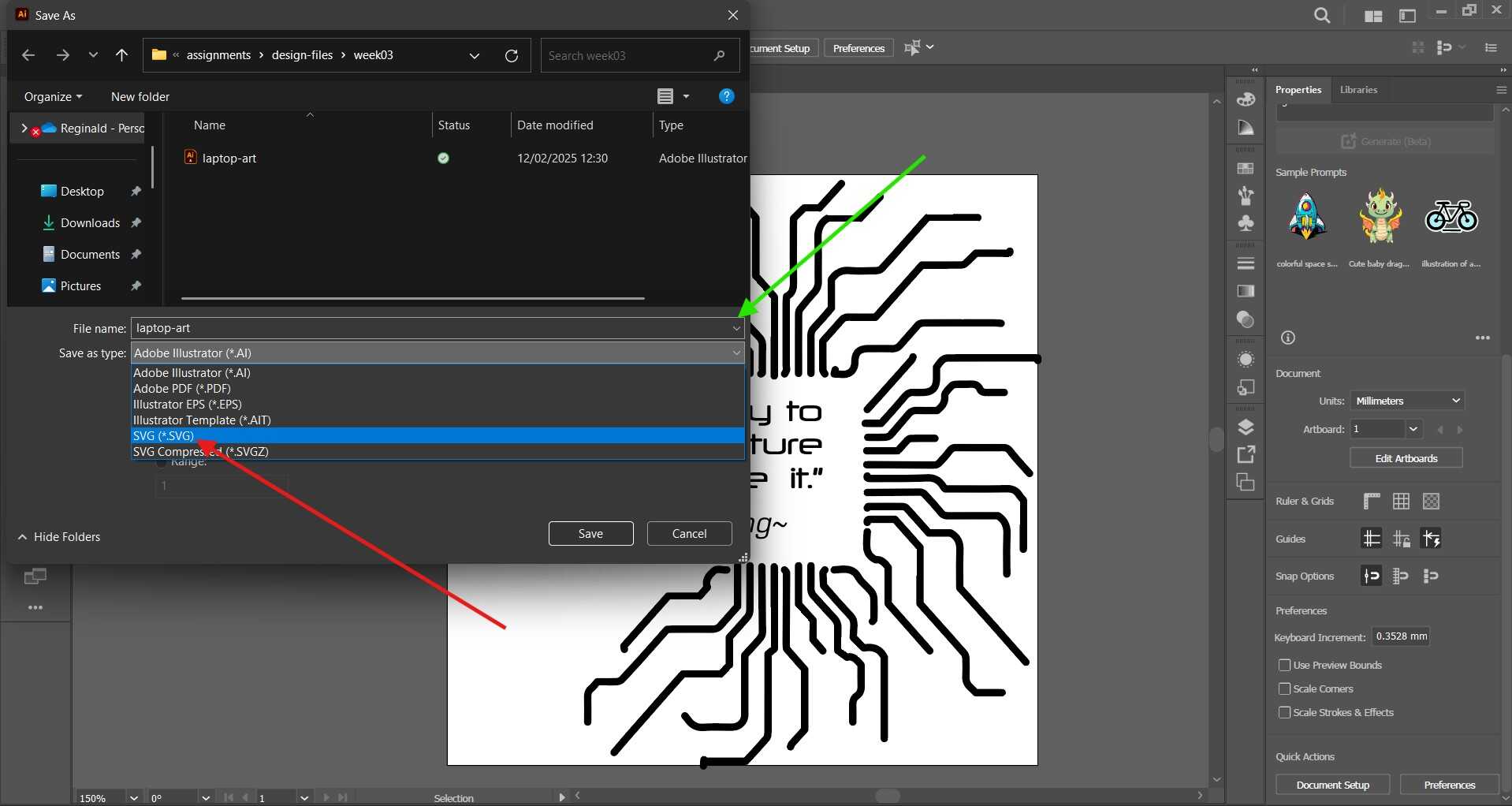
I then Saved My Design:
I finally saved my design as an SVG file by going to File > Save As and selecting SVG as the file format. I also saved the original .AI file, just in case.
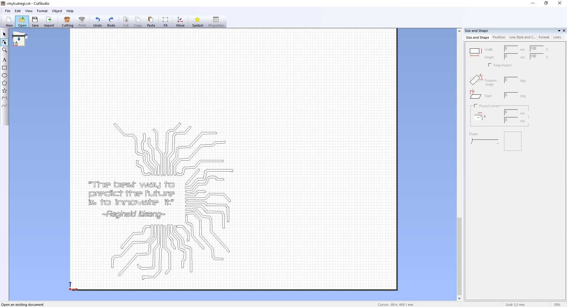
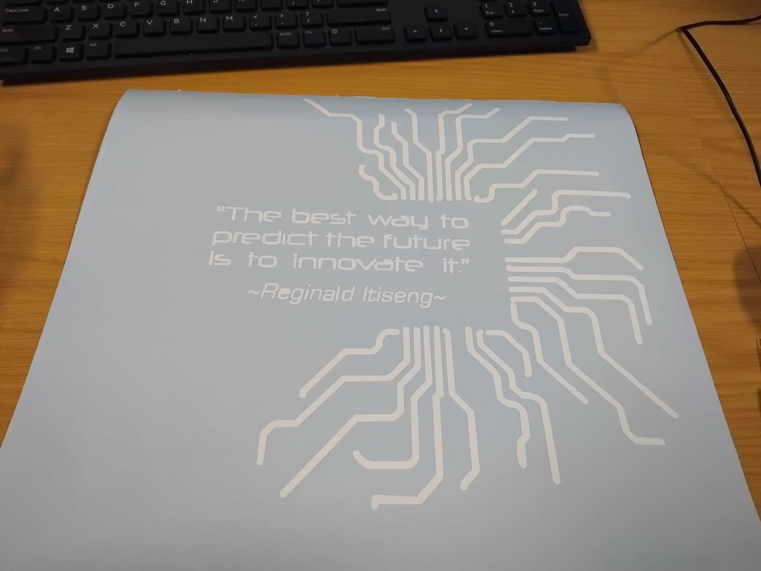
Below is the final design:

-
Import to Vinyl Cutter Software:
I opened my vinyl cutter software and imported the SVG file. I adjusted the settings as needed and sent the design to the cutter.
-
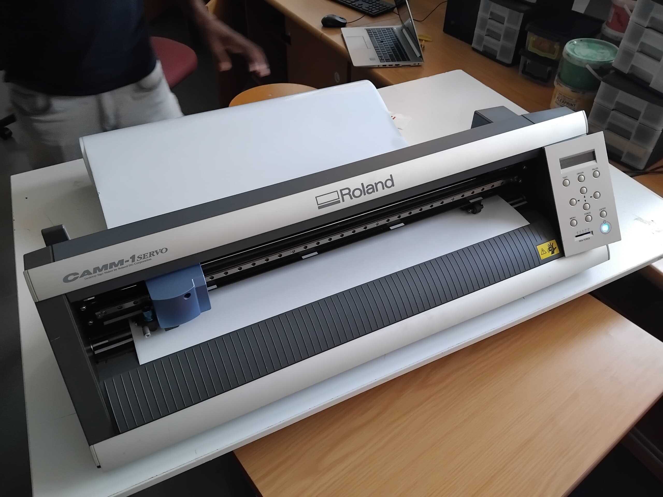
Load the Vinyl Cutter:
I loaded the vinyl cutter with the vinyl sheet and adjusted the settings according to the material I was using. I then sent the design to the cutter and watched as it cut out my logo.
-
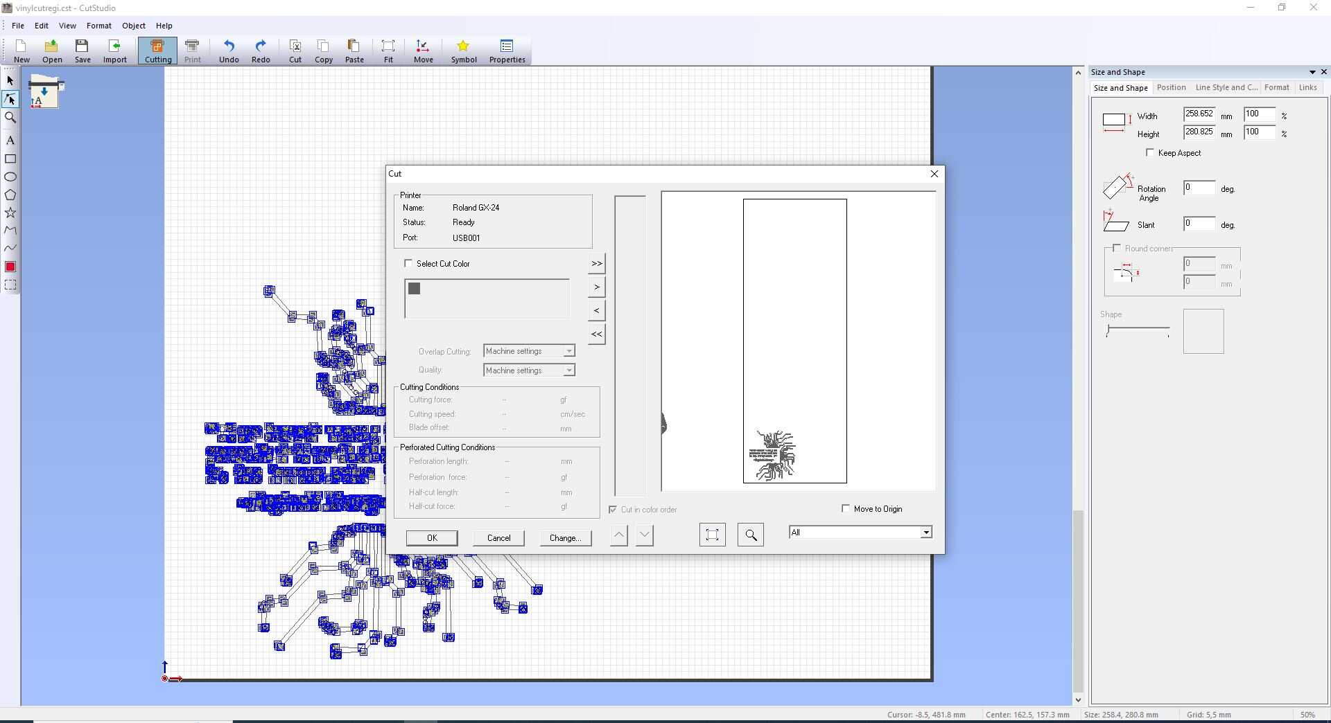
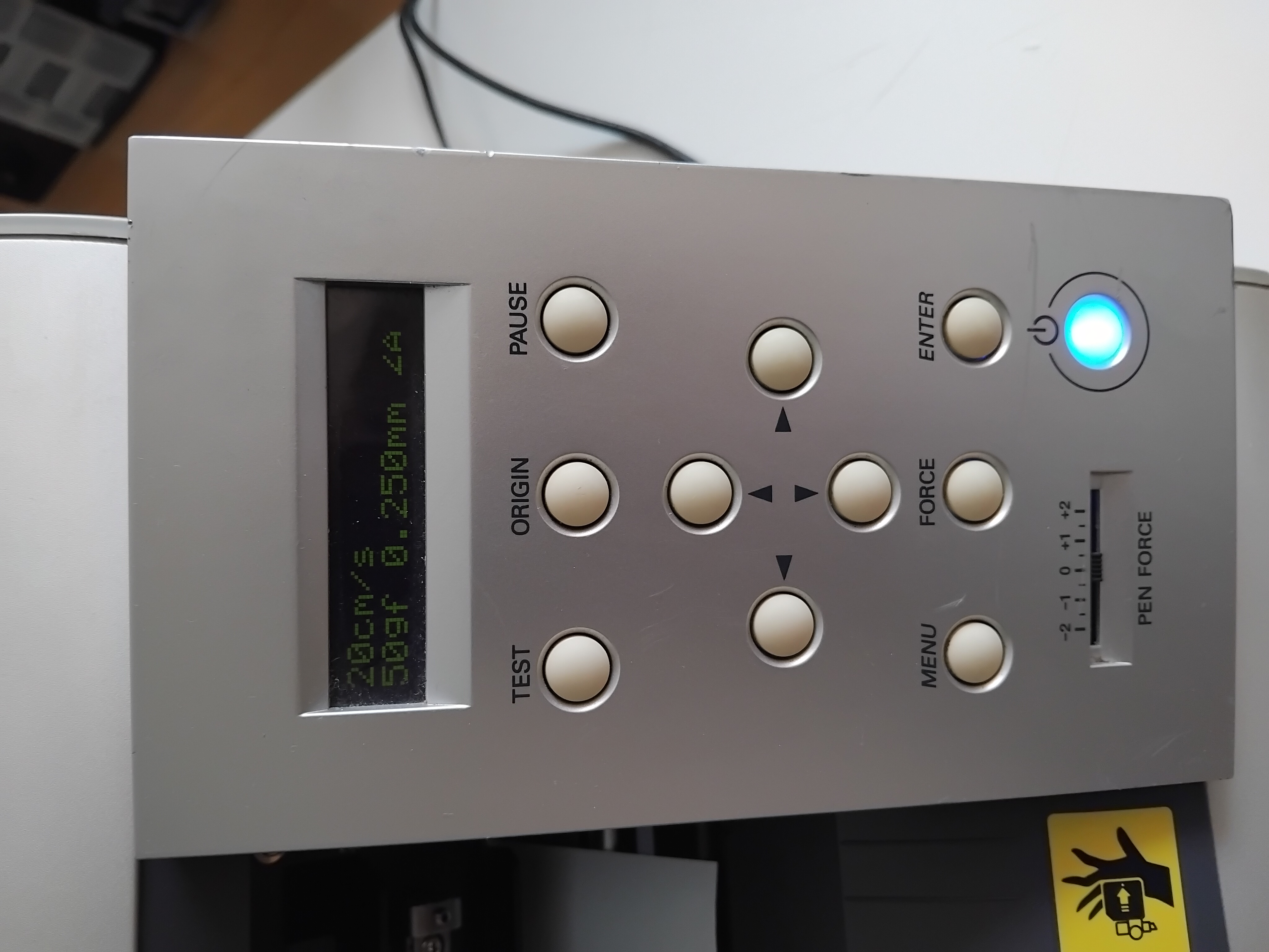
Viny cutter settings:
Below are the settings I used for the vinyl cutter:
-
Weed the Design:
After the design was cut, I weeded out the excess vinyl using a weeding tool. This step is important to remove the parts of the design that are not needed and reveal the final sticker.
-
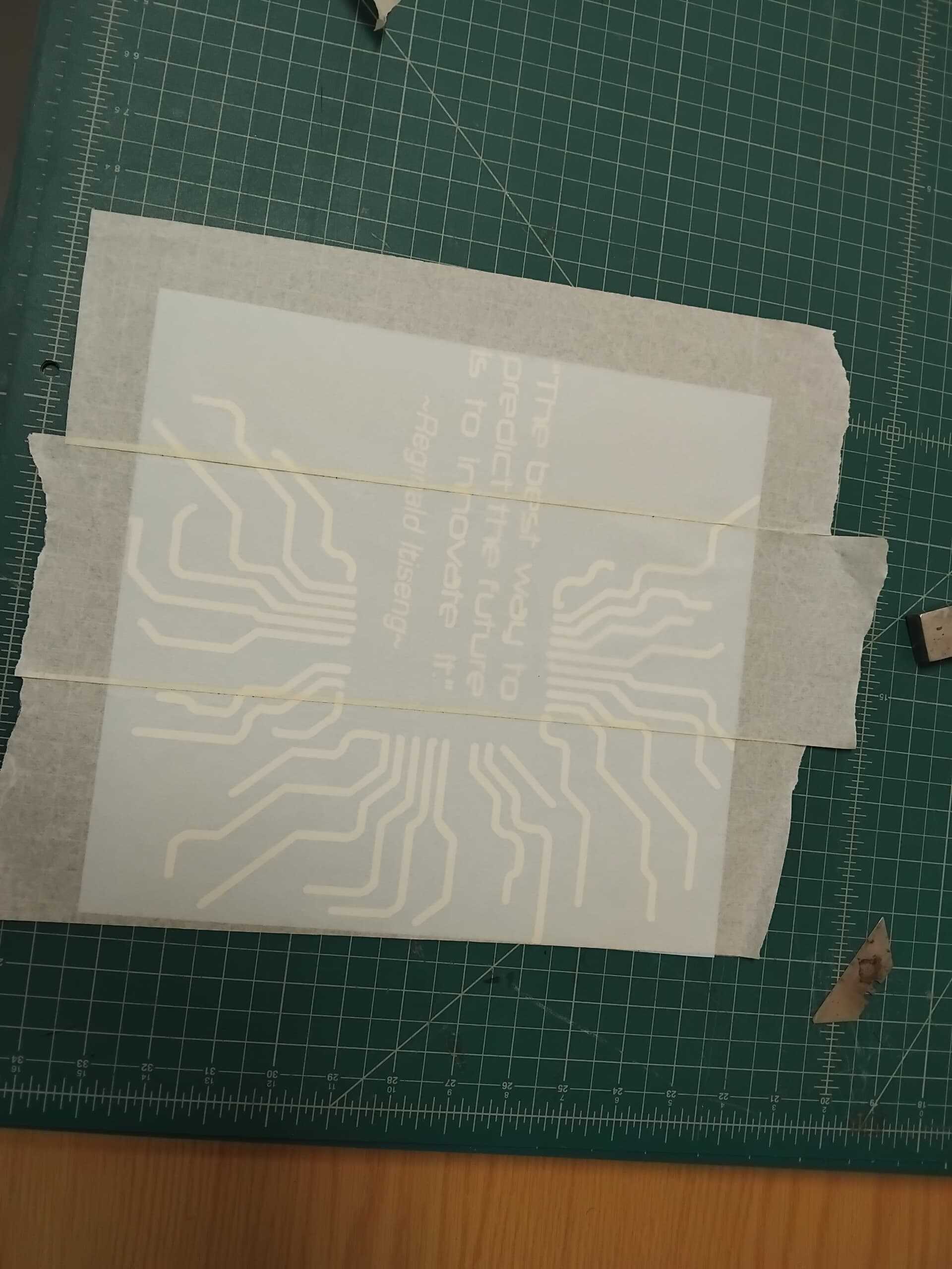
Apply Transfer Tape:
Finally, I applied transfer tape to the design to transfer it to the desired surface. The transfer tape helps to keep the design in place and ensures that it is applied smoothly and accurately. The tranfer tape in this case is just masking tape.
-
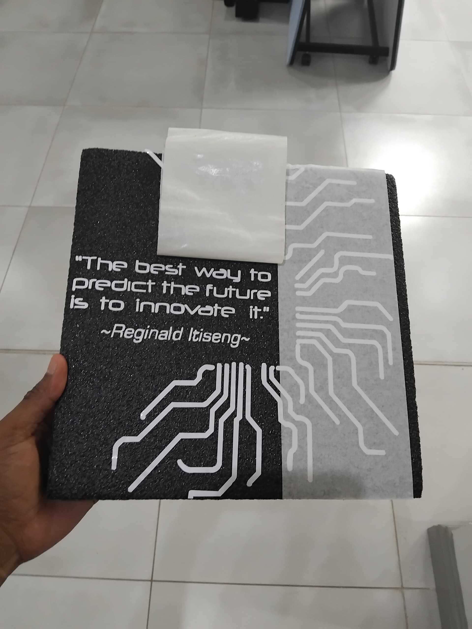
Apply the Sticker:
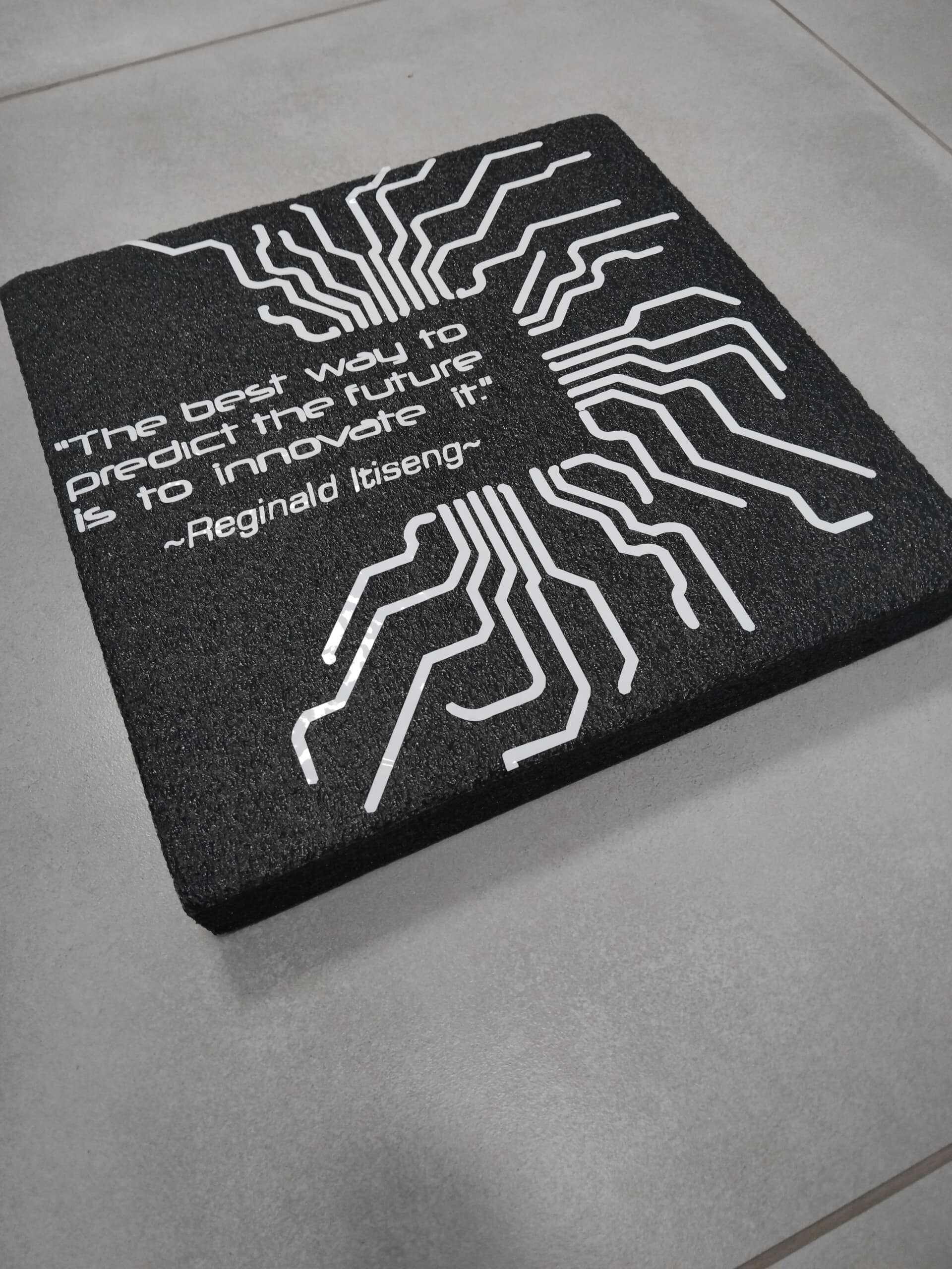
At this point I had already realized that I had accidentally changed the final size of the sticker, making it too big for the space on my laptop. So, I decided to transfer the design onto a different surface. I chose a block made of black padding foam. I carefully placed the sticker on the block and used a squeegee to smooth out any air bubbles. I then removed the transfer tape, revealing my logo in all its vinyl glory🎉.
Laser Cutting
Now, onto the laser cutting assignment🫣. This is where things get a bit more intense😤. Designing a parametric construction kit sounds fun, but let's be honest, the thought of using a laser cutter has me a bit nervous😰. I mean, who wouldn't be worried about accidentally setting something on fire? But hey, no risk, no reward, right? Let's dive in and see what we can create without burning down the lab!
Steps to Design a Parametric Construction Kit in SolidWorks
I decided to focus on designing a single parametric shape with interlocking structures. This shape was carefully chosen and designed to explore the versatility and potential of parametric design in creating complex and interesting structures. By concentrating on one shape, I aimed to understand the importance of precision and creativity in designing parts that fit together seamlessly.
-
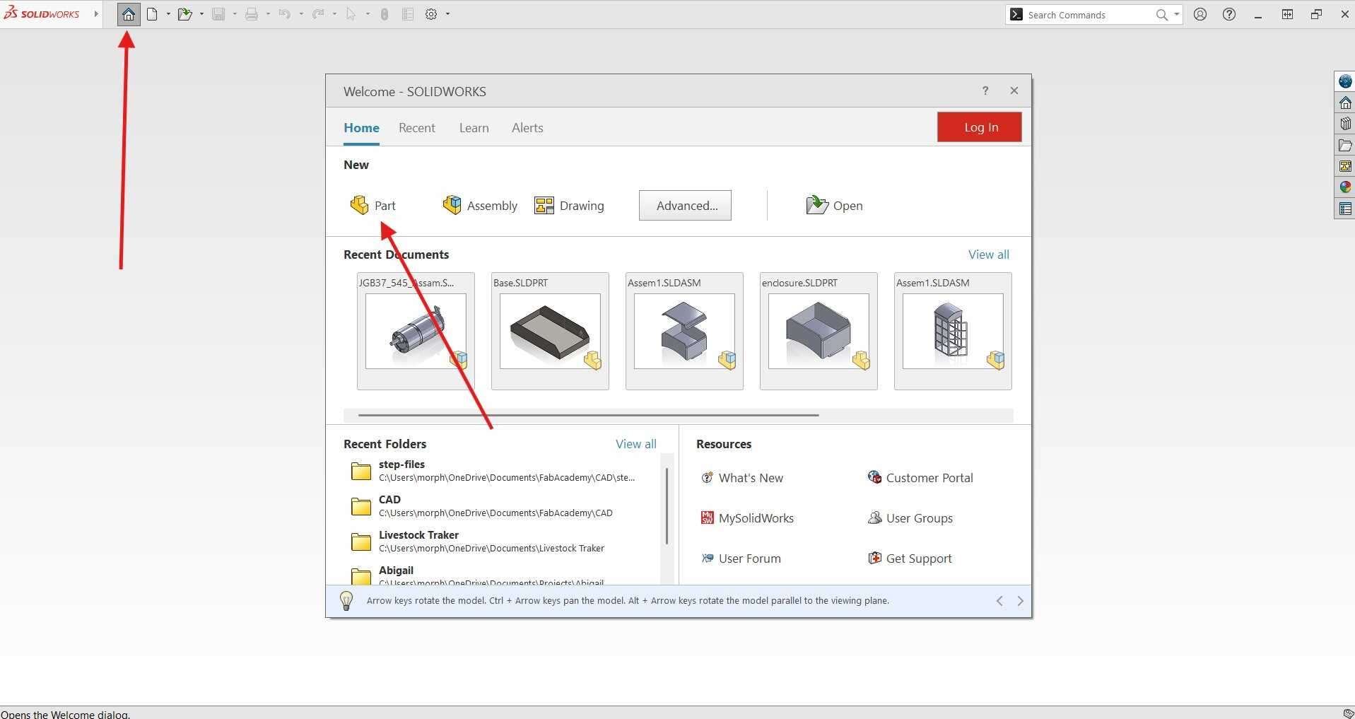
Opening SolidWorks And Creating a New Part:
I launched SolidWorks by double-clicking the desktop icon and created a new part document. This was probably the least stressful part of the entire process, considering I hadn't yet faced the laser cutter😅.
-
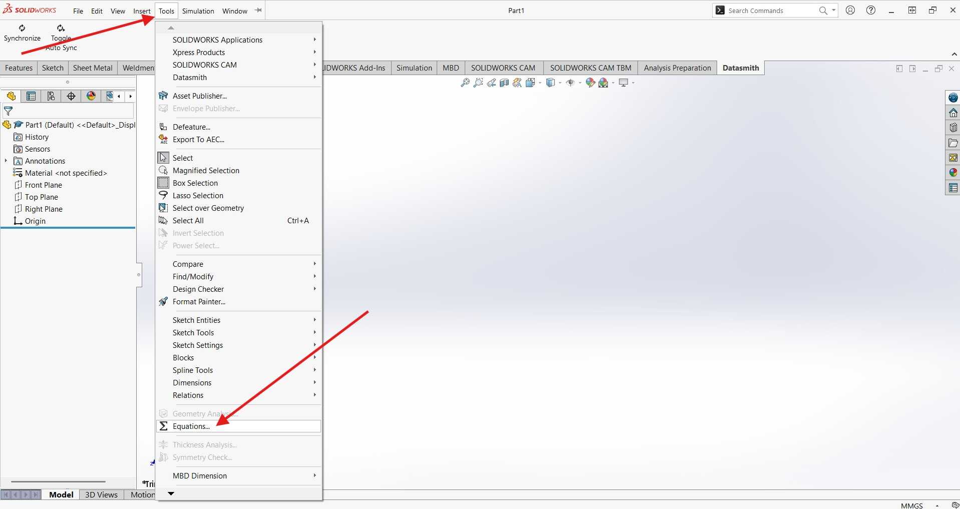
Set Up Parameters:
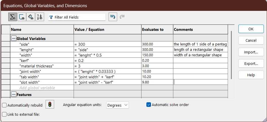
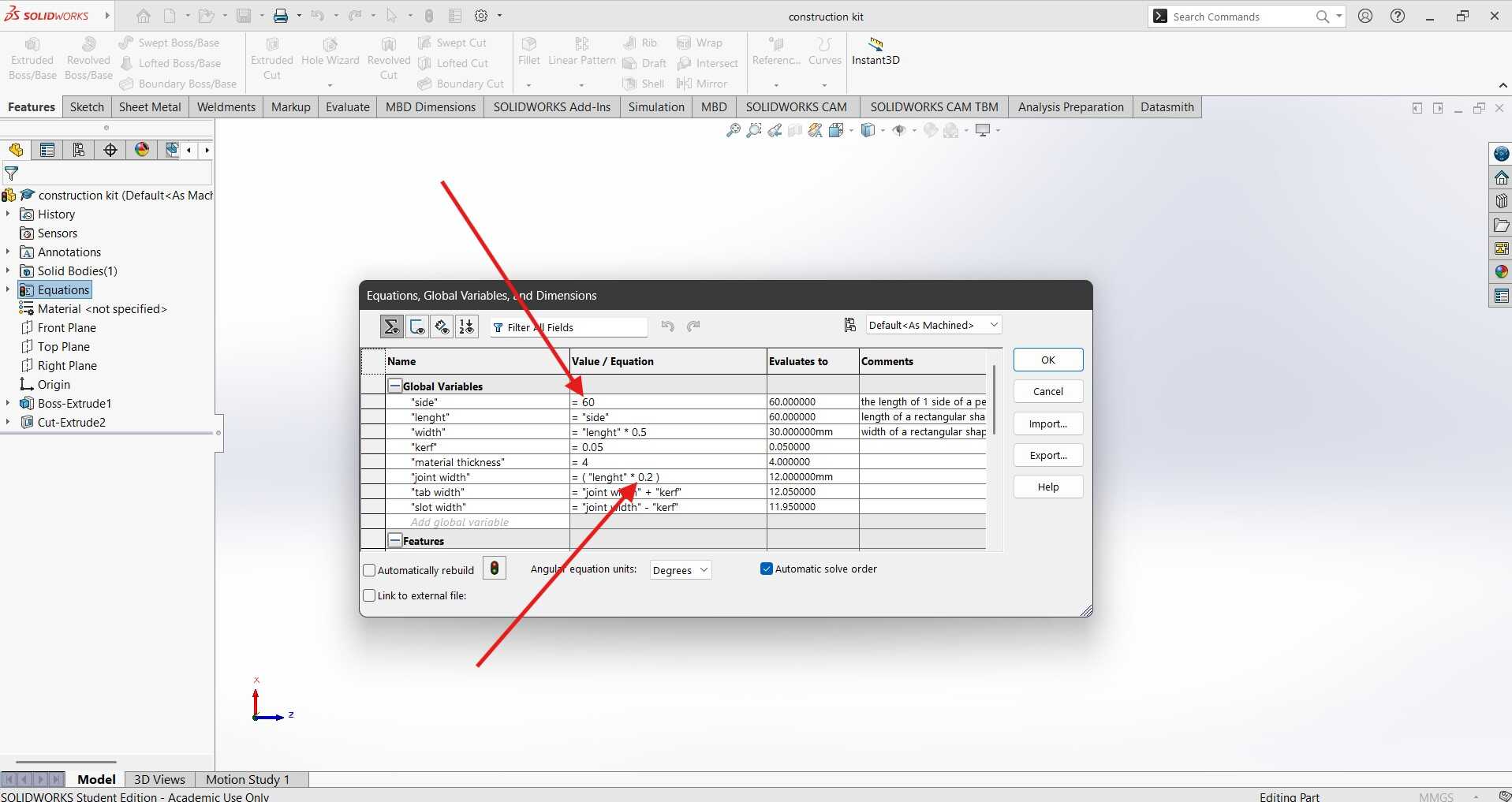
I went to Tools > Equations and defined the parameters for my design, such as material thickness and kerf. This allowed me to easily adjust the dimensions later.
Below are the parameters I set up for the design:
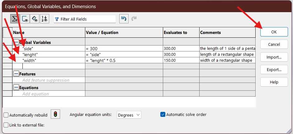
These parameters will help me design the part with the correct dimensions and account for the kerf of the laser cutter.
-
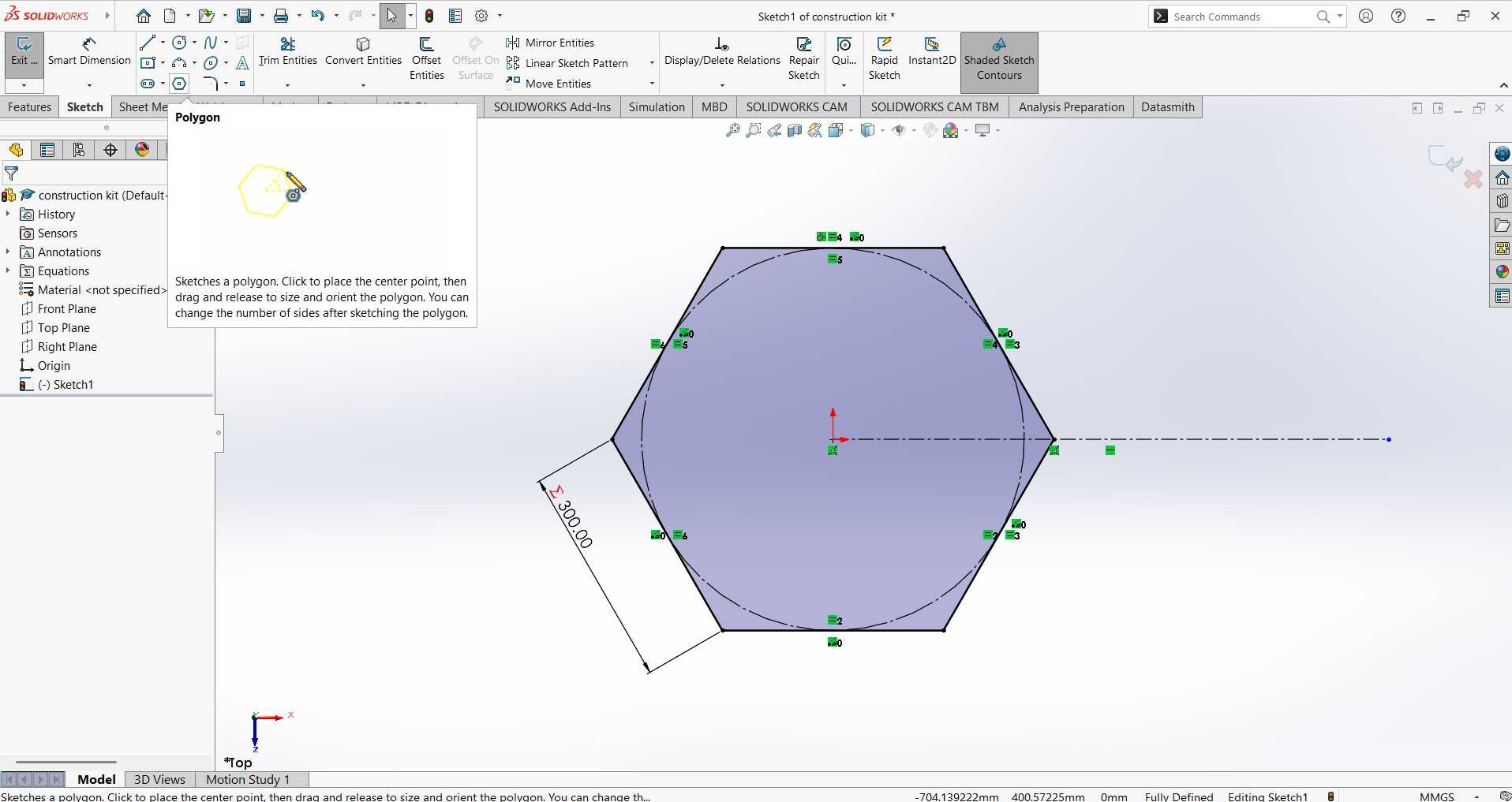
Create a Sketch:
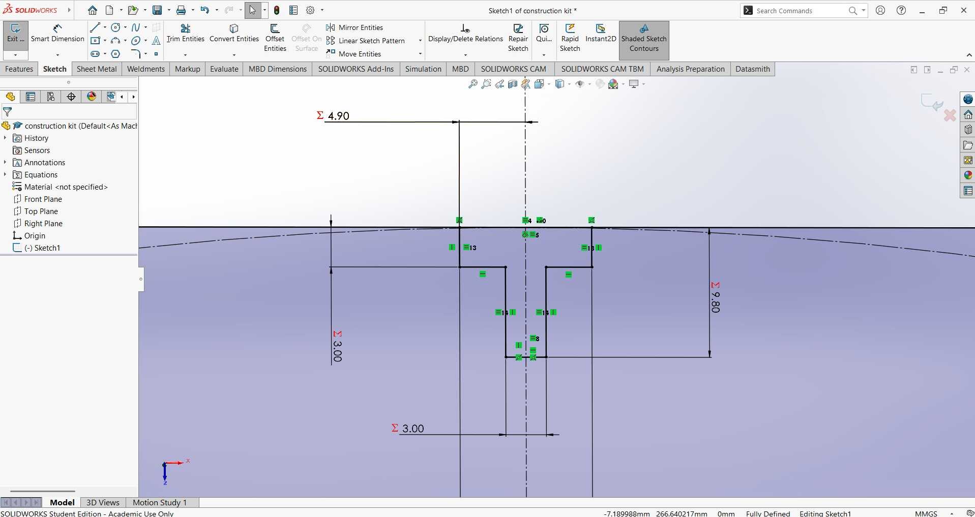
I started a new sketch on the top plane and drew the basic shape of my construction kit part. I used the dimension tool to define the size of the part, referencing the parameters I set up earlier.
The sigma sign (Σ) next to a dimension in SolidWorks indicates that the dimension is driven by an equation or a global variable. This means that the value of the dimension is not manually entered but is calculated based on a predefined formula or parameter. Using equations and global variables helps in creating parametric designs where changes to one dimension can automatically update related dimensions, ensuring consistency and accuracy in the design.
After the shape of the piece is sketched and fully defined, I then drew the slot on one of the faces. Being fully defined means that all the dimensions and constraints are specified, leaving no ambiguity in the sketch. This ensures that the sketch will not change unexpectedly when modifications are made. The Line tool was used for this.
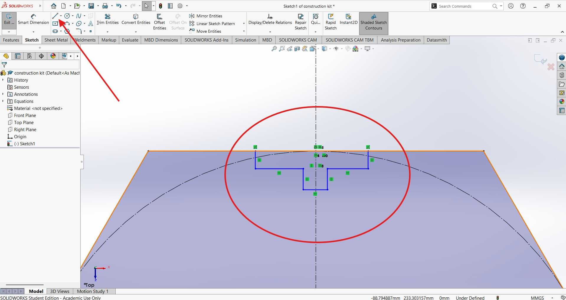
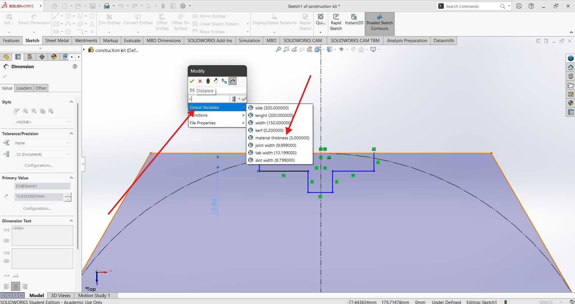
Next the shape of the slot was contrained to material thickness and slot width global dimensions.
below is the complete sketch of the slot on the shape, the trim entities tool was then used to remove the edge that wasnt needed.
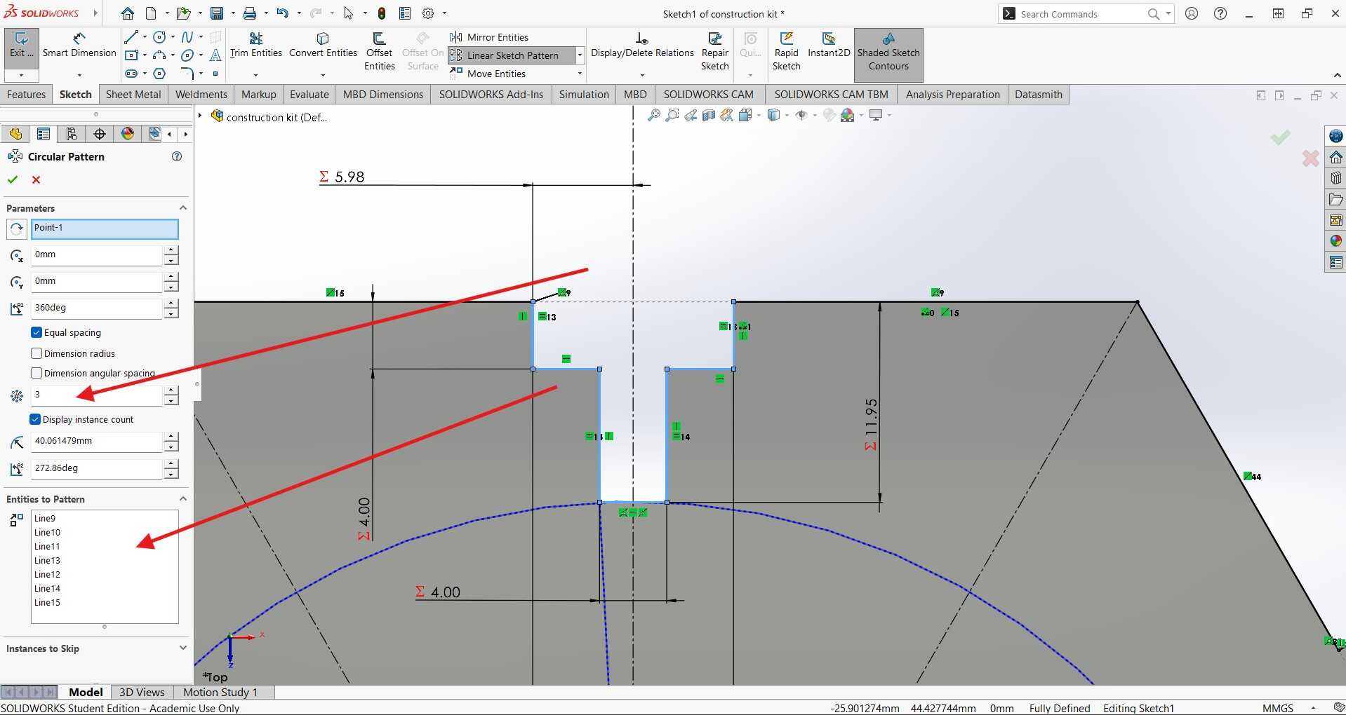
Next, I used the Circular Pattern tool to add three more instances of the same slot feature on the other faces of the hexagon, ensuring they were evenly spaced. I selected the lines of the slot as the entities to pattern, set the number of instances to 3, and specified a 360-degree rotation around the center of the hexagon. These settings were added in the Property Manager that pops up after clicking the Circular Pattern command. It was like giving my hexagon a stylish haircut, making sure each slot was perfectly aligned and ready to fit together seamlessly. Who knew geometry could be so fashionable?
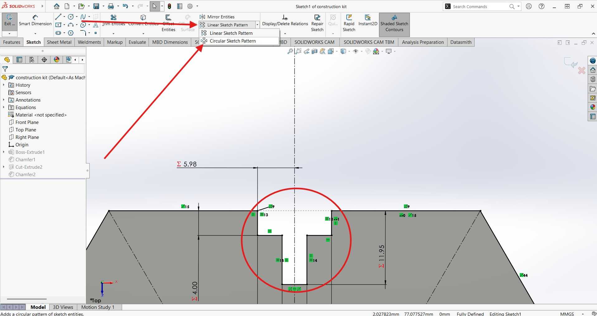
Bellow are the settings added to the Property manager of the circular pattern command:
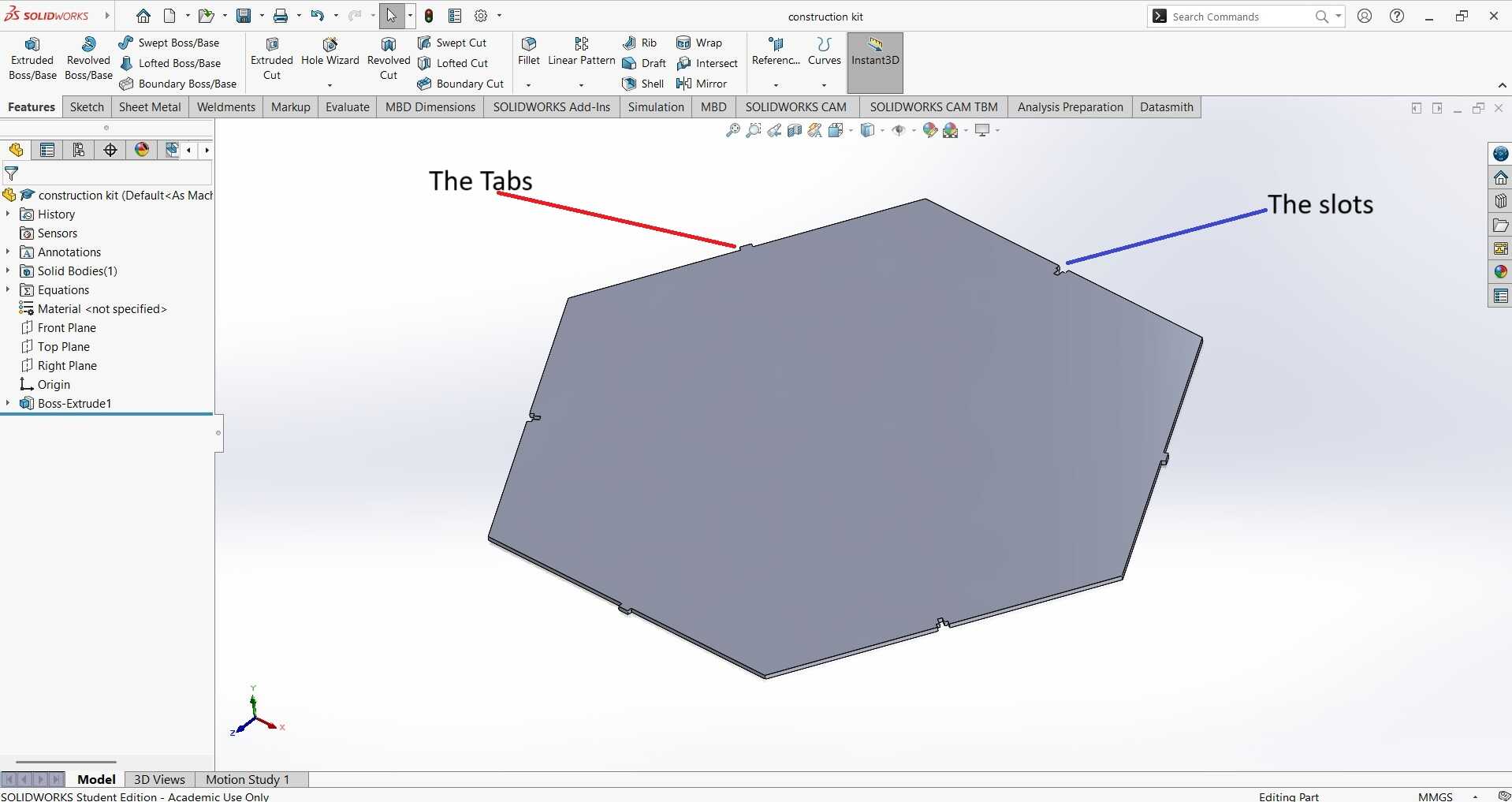
The previous step was repeated for the other faces of the hexagon to create the tabs on the remaining 3 faces to get the result bellow:
⚠️⚠️
It was at this point that I realized my first mistake. My construction piece was huge! One side was 300 mm long, and I have no idea what I was thinking when I used this number. This meant each side of the shape was the size of a 30cm ruler. It's a good thing that the design was made parametric because I went back and adjusted the values. Crisis averted, and no giant hexagons were harmed in the making of this project! 😅😅😅
⚠️⚠️
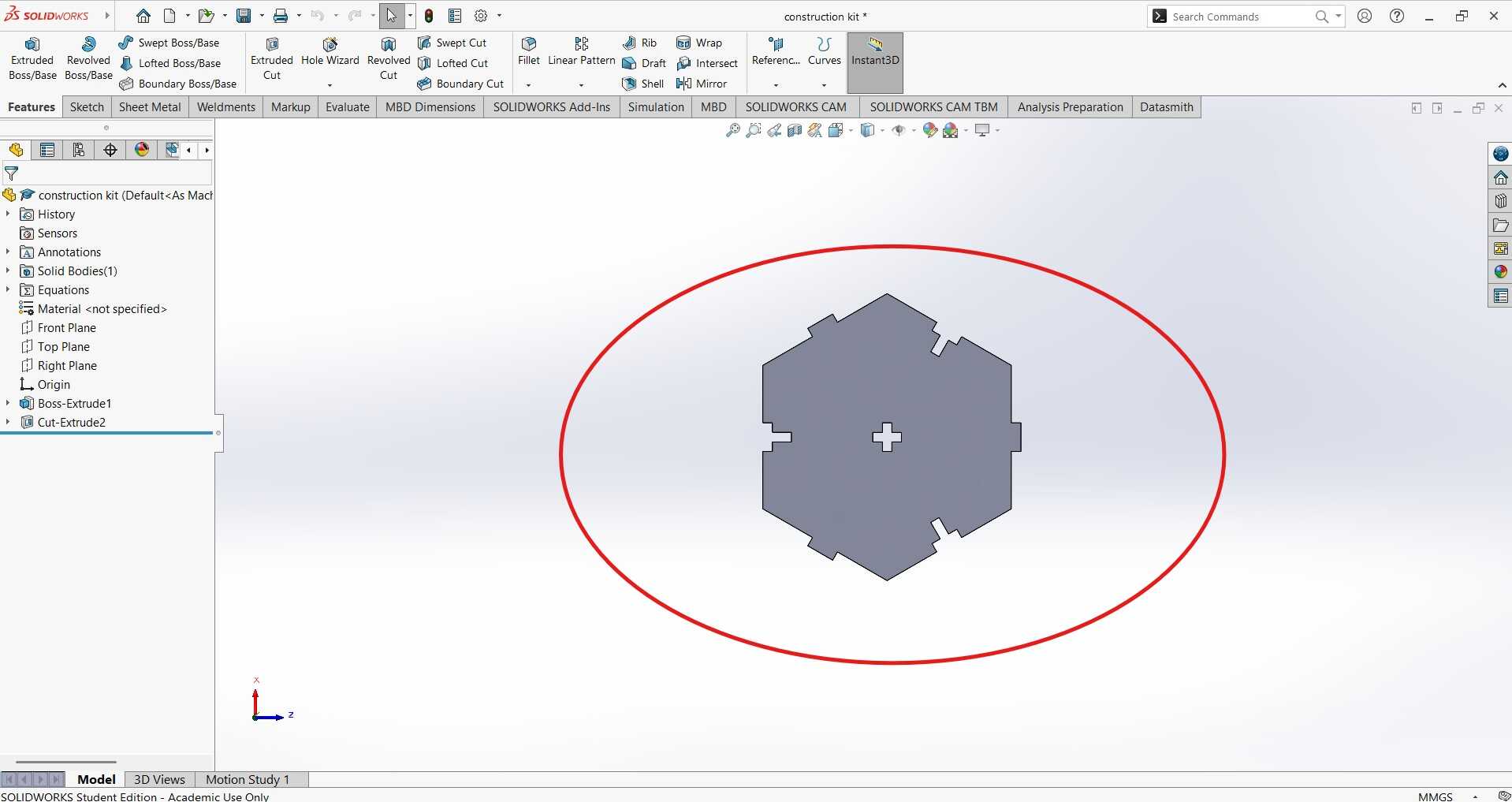
From 300mm I reduced the length of 1 side to 60mm and then adjusted the joint width to be the length of 1 side multiplied by 0.2 to give a value of around 10mm which is going to be the basis or reverance value for all the joints.
Changing the 2 values as shown above adjusted everything and i got the result below:
-
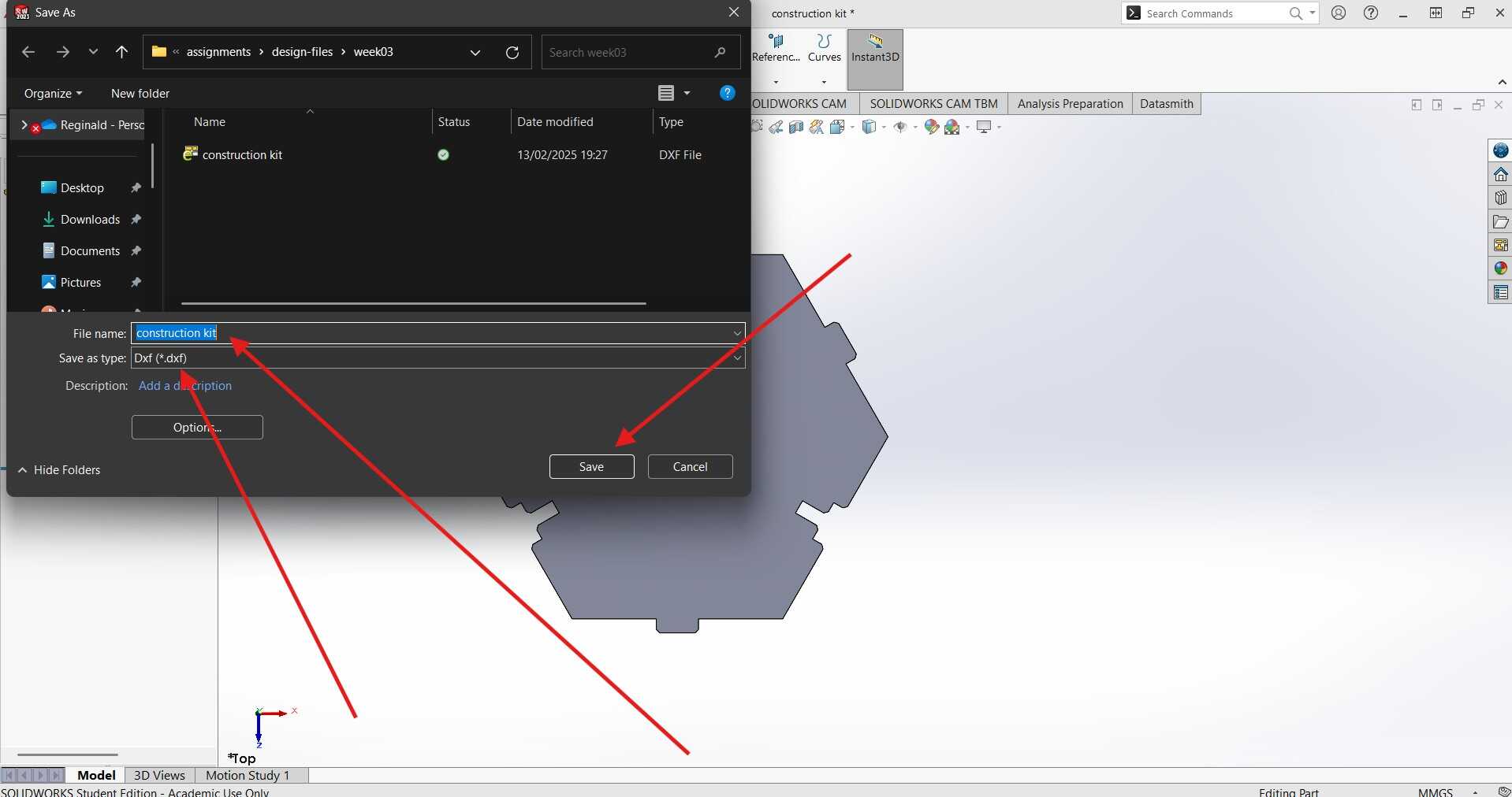
Save and Export:
After ensuring that my design was perfect and ready for the laser cutter, I saved the file as a DXF. This format is essential for laser cutting because it preserves the vector paths needed for precise cutting. I went to File > Save As and selected DXF as the file format. As I clicked 'Save', I couldn't help but chuckle at the thought that my fate was sealed - there was no avoiding the laser cutter now😂.
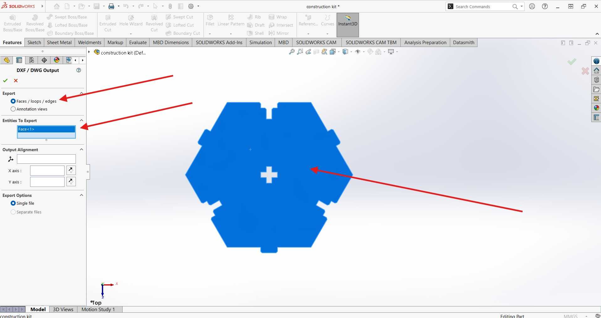
After hitting save, a properties tab will apear where I had to choose what to export as dxf. now sisnce i need the flat shape of the part i selscted the Faces/loops/edges option the clicked on the top face of my part. at that point everything is set and i could hit the green tick ✅.
-
Import to Laser Cutter Software:
RDWorks is a software used for controlling laser cutting machines. To import the DXF file into RDWorks, I opened the software and clicked on the 'File' menu, then selected 'Import'. I navigated to the location of my saved DXF file and selected it. Once the file was imported, I adjusted the settings such as power, speed, and the number of passes according to the material I was using. After ensuring all settings were correct, I sent the design to the laser cutter by clicking on the 'Start' button.
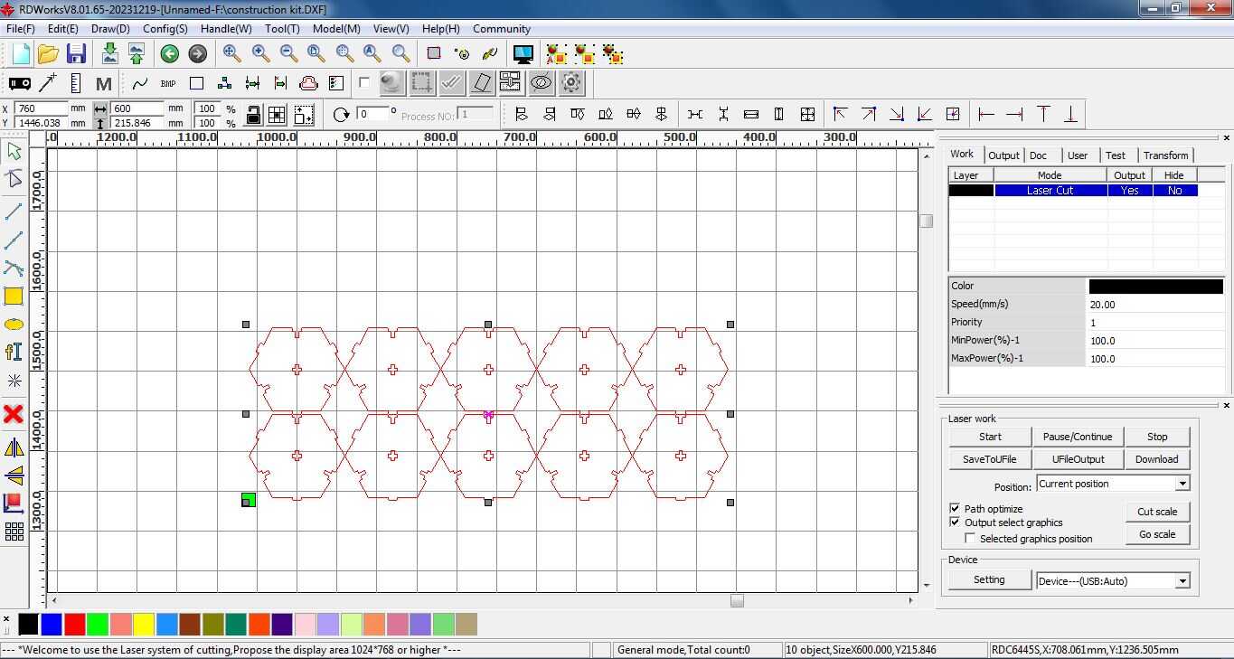
The power and speed were informed by the tests done on the group work. power of 100 and speed of 20 was note to be ideal fro cutting througn a 4mm thick board of plywood.
-
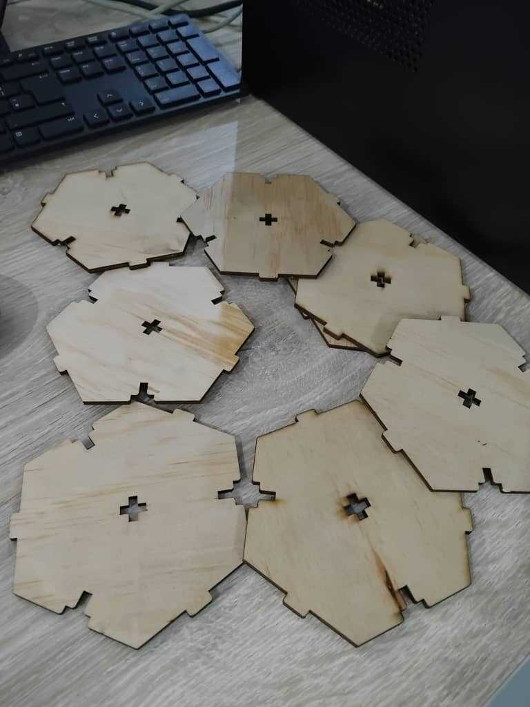
Extracting The Pieces:
After the laser cutter was done cutting, I extracted the pieces from the board.
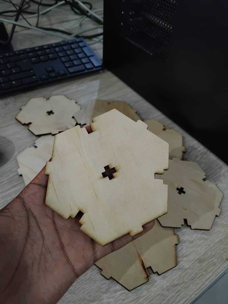
Below is the final result of the lazer cutting:
-
Assembling the Construction Kit:
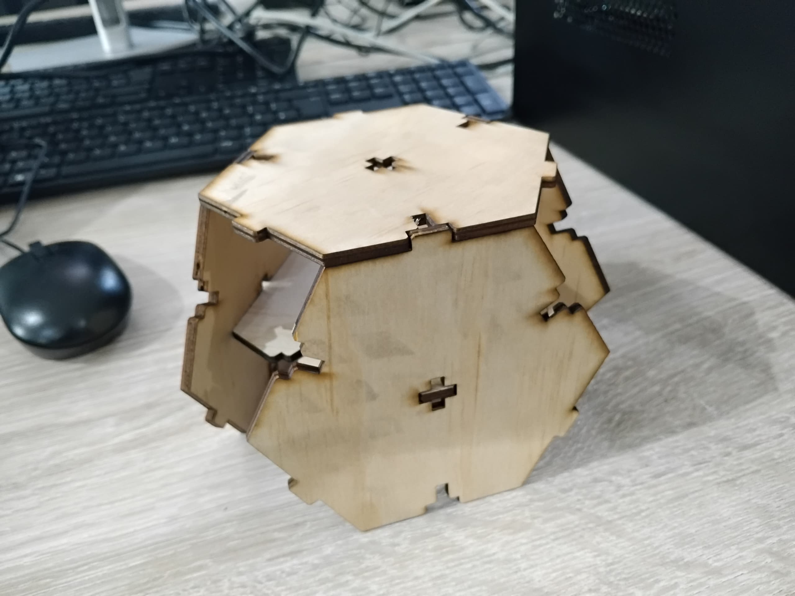
After extracting the pieces from the board, I attempted to assemble the construction kit by fitting the tabs into the slots. Unfortunately, the pieces were too loose and did not fit together as tightly as I had hoped. I believe the issue was due to an incorrect kerf adjustment in my design. The kerf, or the width of the material removed by the laser, was not properly accounted for, resulting in slots that were slightly too wide. This experience taught me the importance of precise measurements and adjustments when working with laser cutting, and I plan to refine my design to achieve a better fit in the future.
Final Thoughts
This week was a rollercoaster of emotions🎢. From the excitement of creating my first vinyl sticker to the nervousness of using the laser cutter, it
was definitely a week of highs and lows. But in the end, I learned a lot about the capabilities of these machines and how to design for them effectively. I'm looking forward to applying these skills in future projects and exploring the endless possibilities of digital fabrication.
Design files
You can download the design files for the vinyl sticker and the parametric construction kit below:
-
For the Vinyl Sticker:
-
For the Parametric Construction Kit: