8. Electronics Production
Group assigment
- Characterize the design rules for your in-house PCB production process: document feeds, speeds, plunge rate, depth of cut (traces and outline) and tooling.
- Document the workflow for sending a PCB to a boardhouse
- Document your work to the group work page and reflect on your individual page what you learned
Link to a Group page of Electronics Production
Individual assigment
- Make and test a microcontroller development board that you designed
Ploting PCB
To start off this assigment, I used PCB design I did in week 6 of electronic design assignment which can be found here.
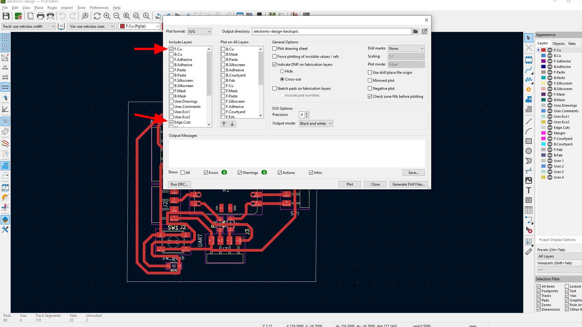
I started by exporting svg file of the PCB
Note:Uncheck everything expept F.Cu and Edge.Cuts layers as highleghted.
Generating g code with Mods
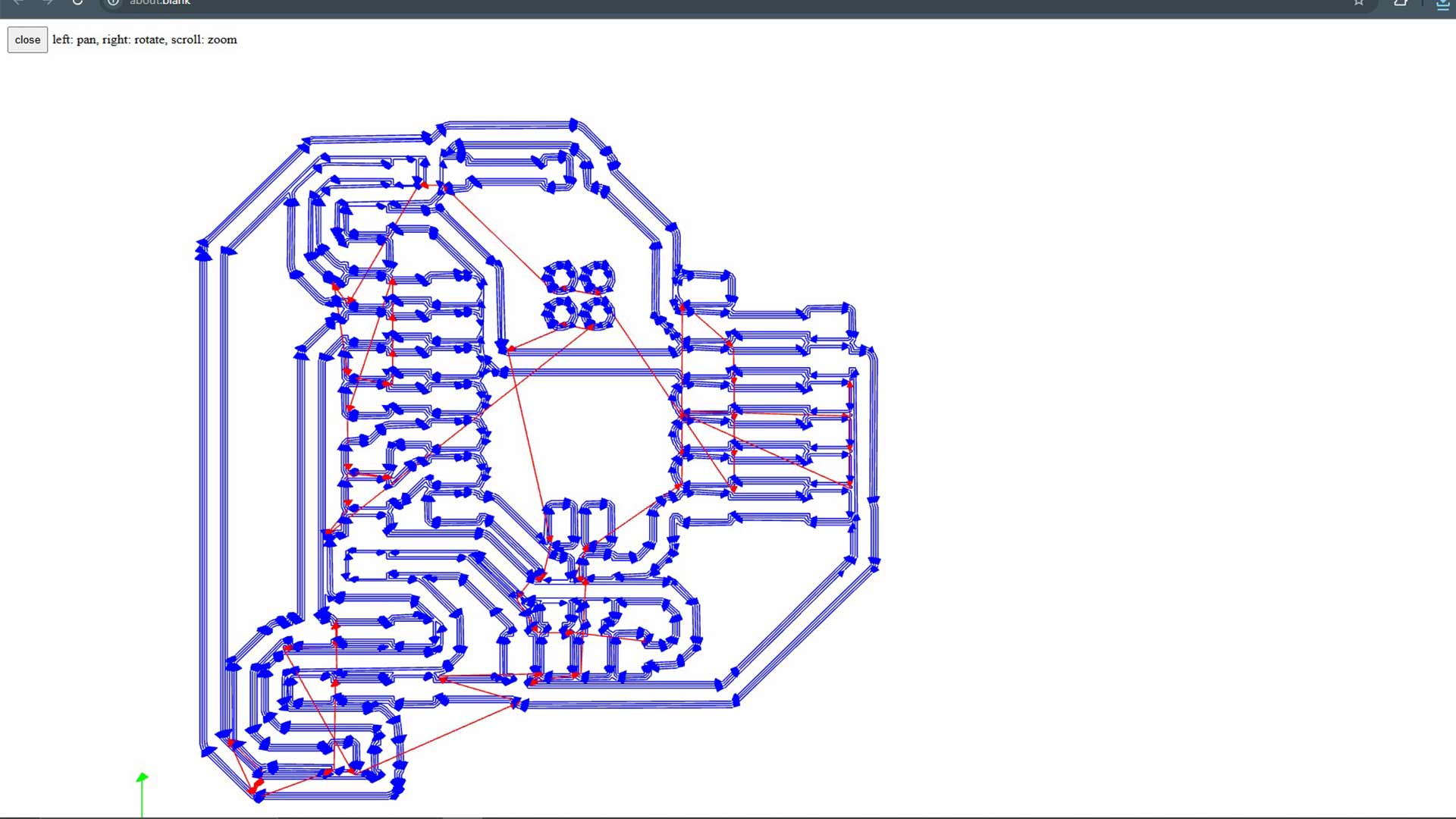
Using modsprojects.org, I imported the SVG file into Mods, inverted the design as necessary, and specified tool parameters such as diameter, offset number, and cut depth.
First step is to import svg file and invert the section
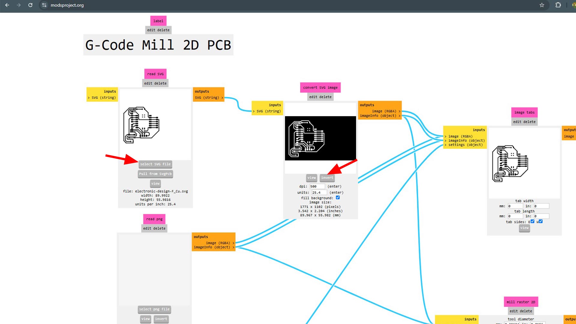
Then I checked the mill trace to
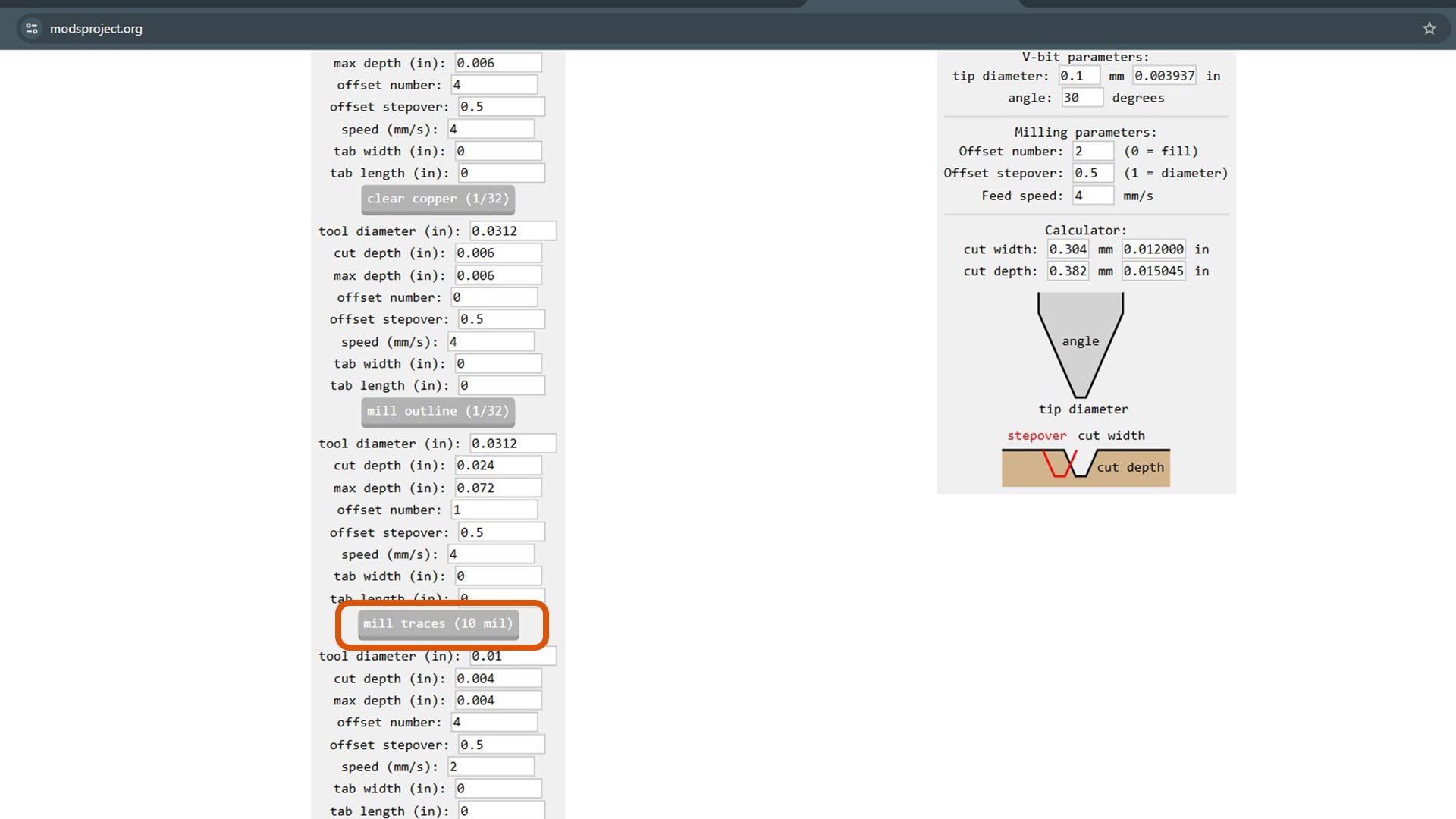
Specify tool parameters mainly tool diameter and offset number as well as cut depth.
After setting parameters, I calculated the toolpaths, which opened in a new window for review.
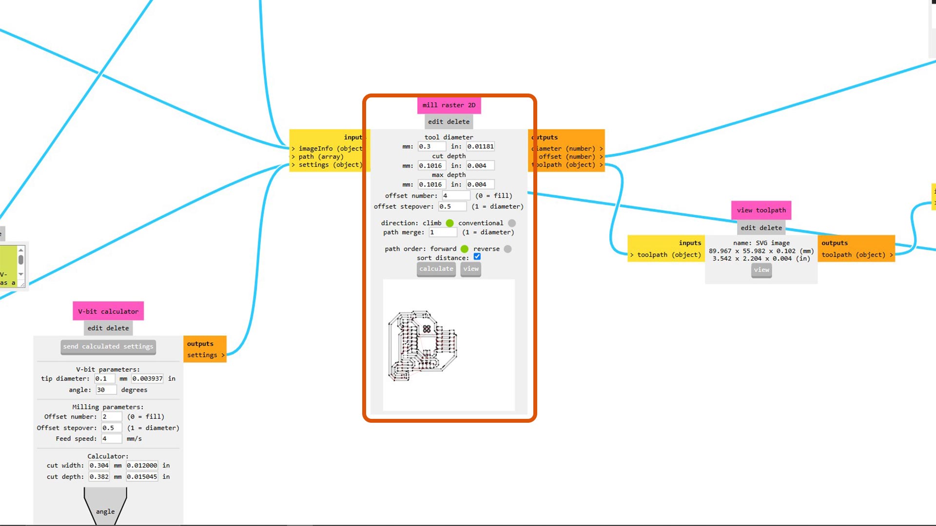
View of traces
Setting up machine
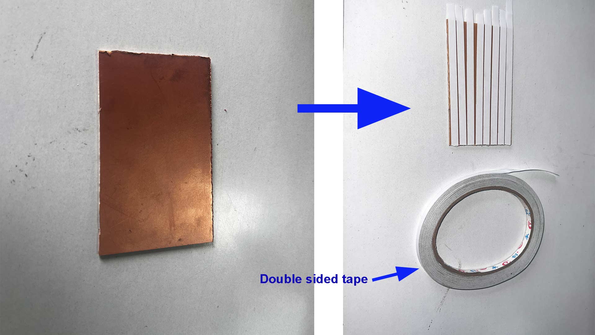
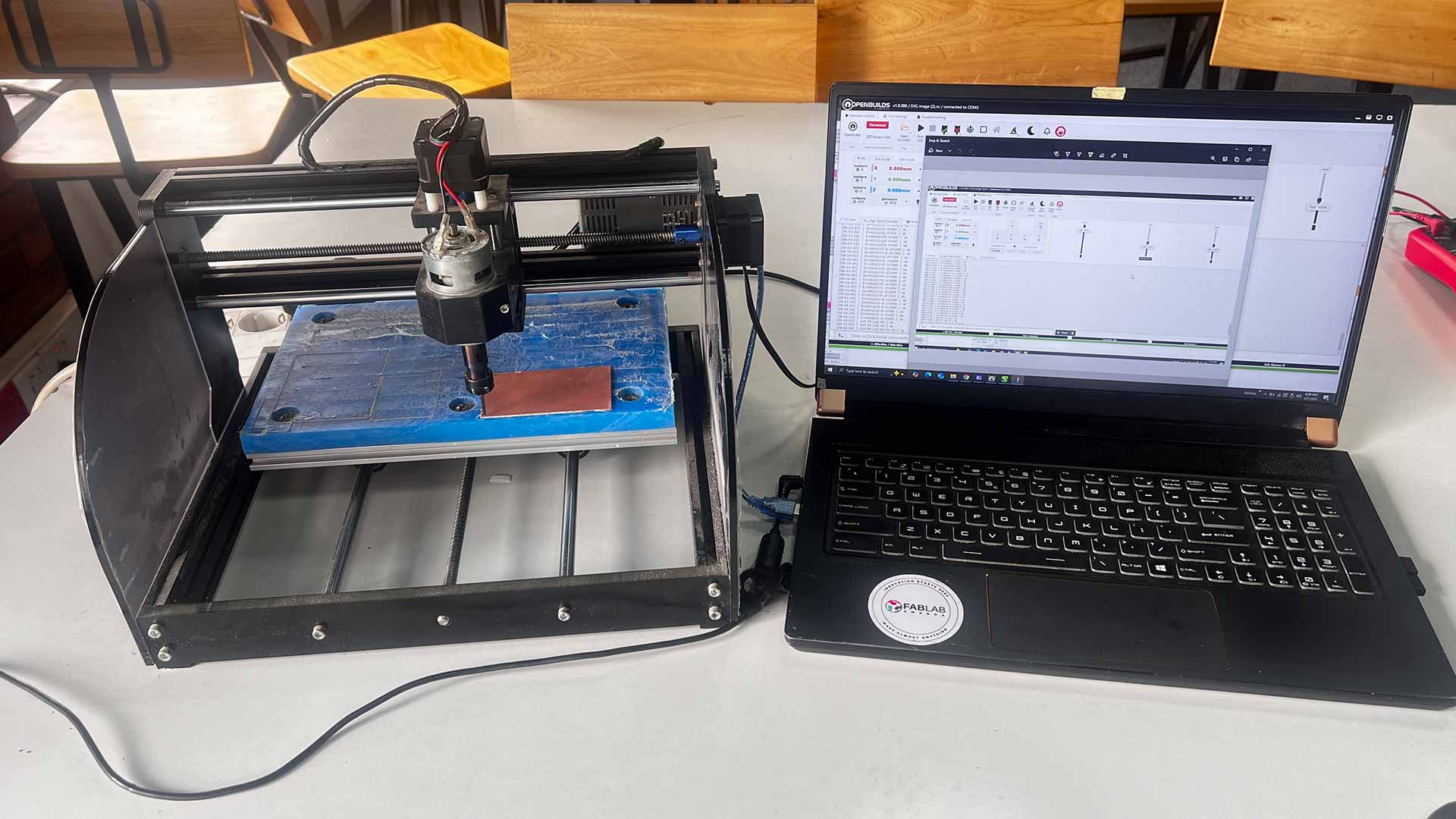
I first adhered the copper board to the milling machine using double-sided tape and connected the machine to his computer via USB cable
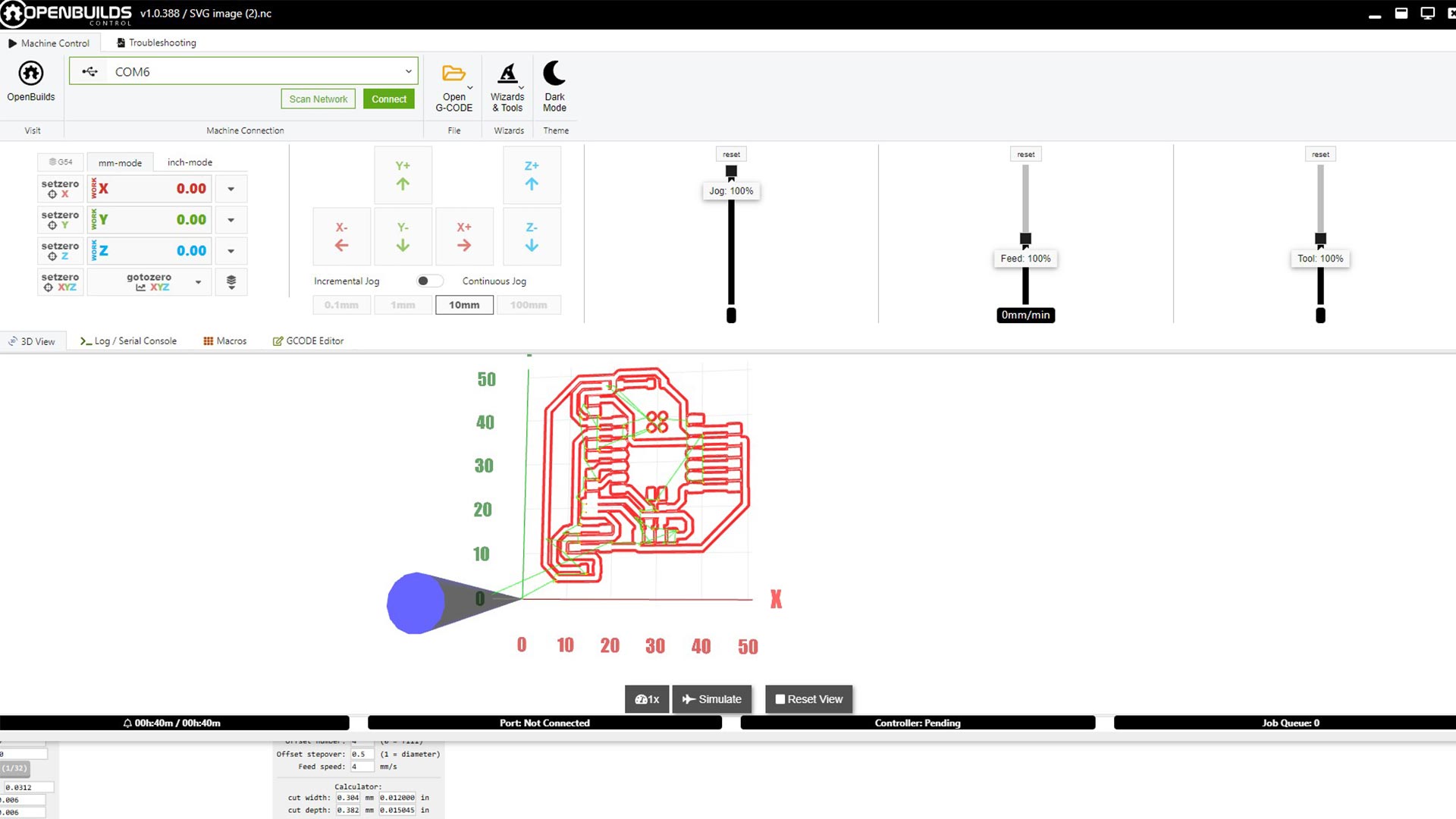
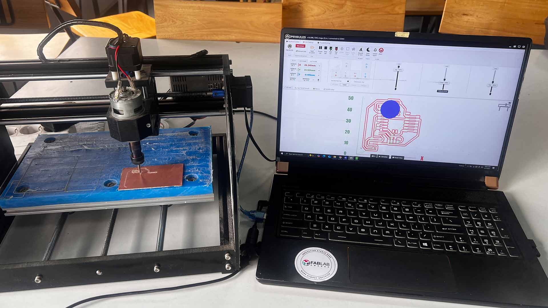
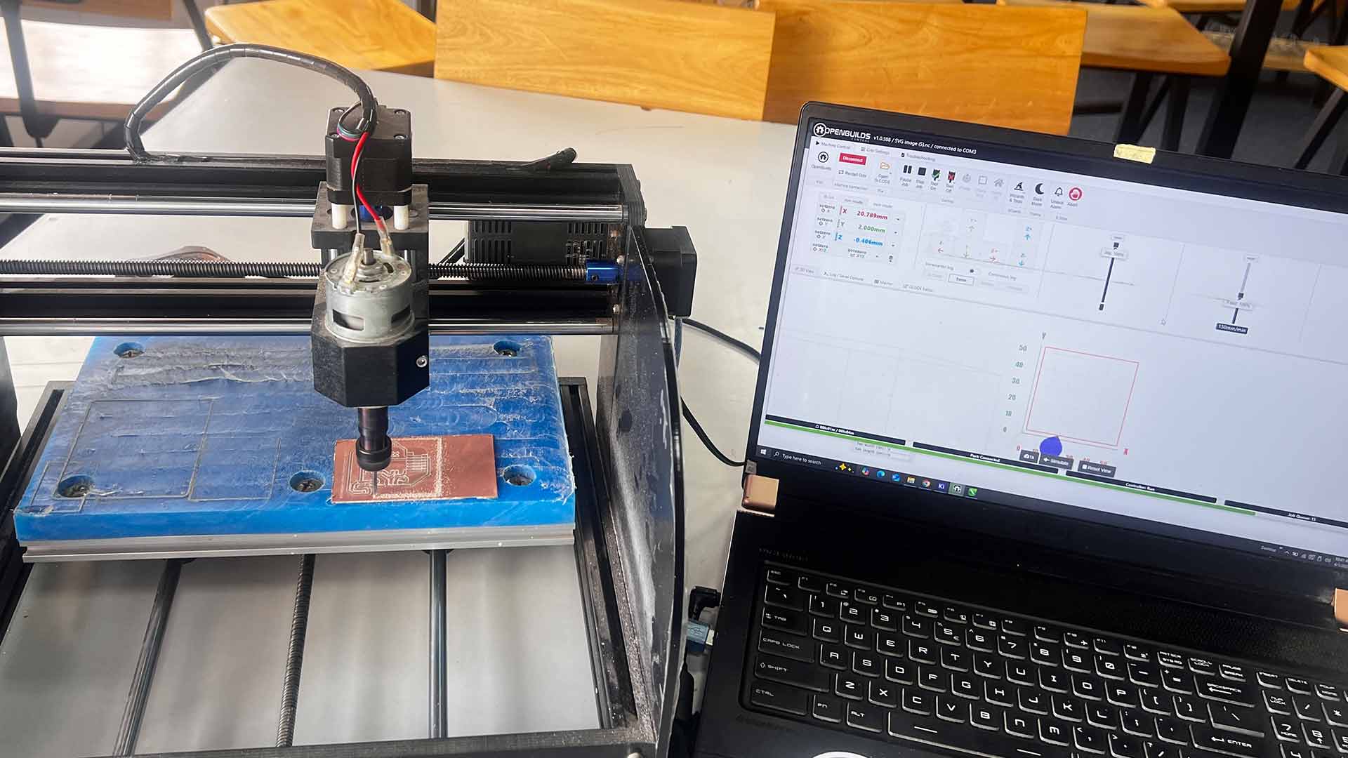
I utilized OpenBuilds Control software to manage the milling process.
Note: Make sure to set origin points correctly x, y and z axes.
I opened the file in Open build to preview.
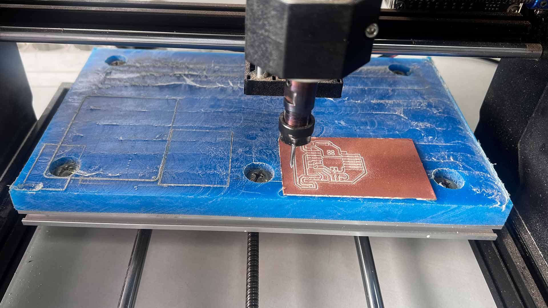
After mill pcb, I also cut out the sape
I aligned aligned all necessary components.
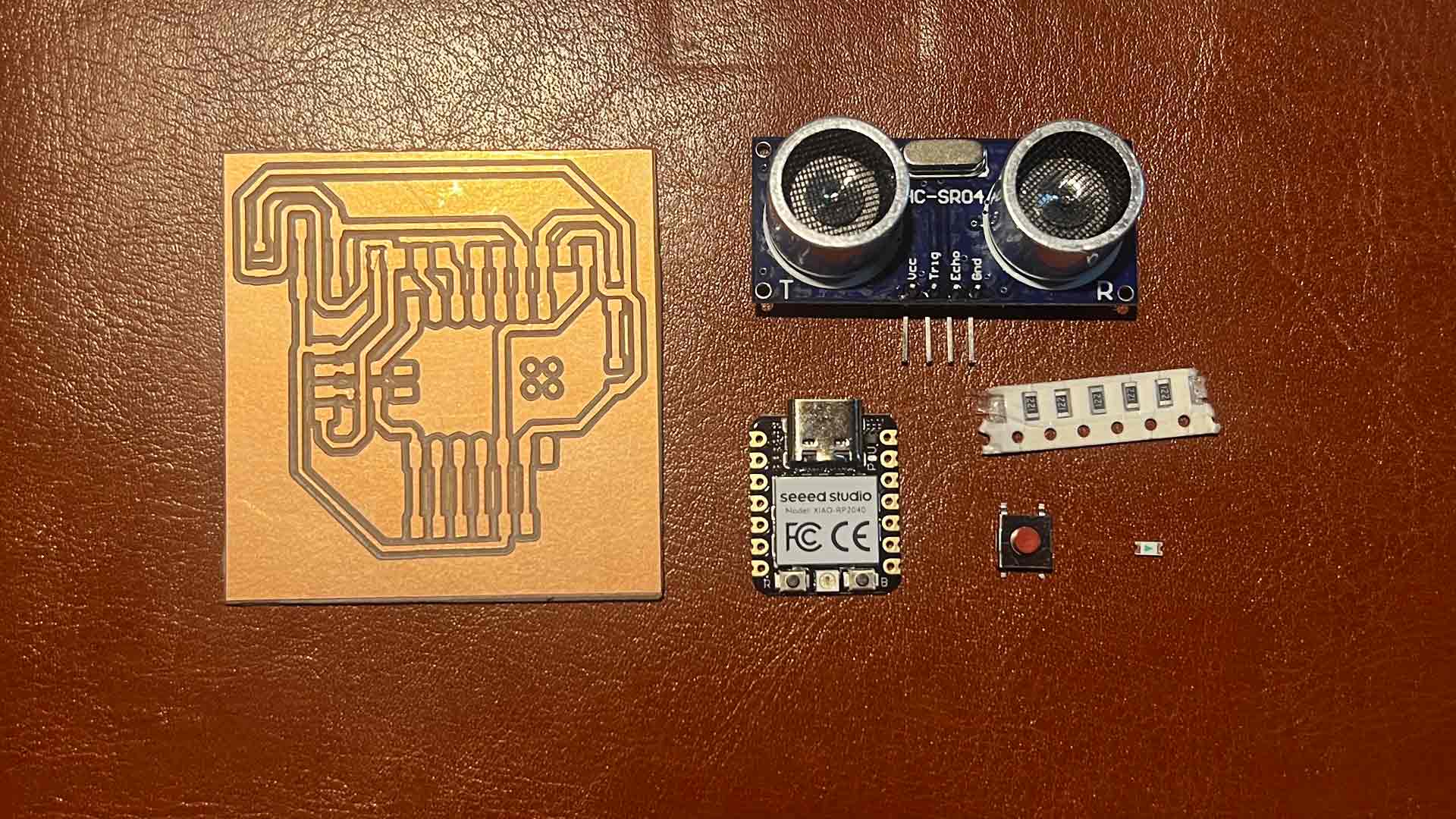
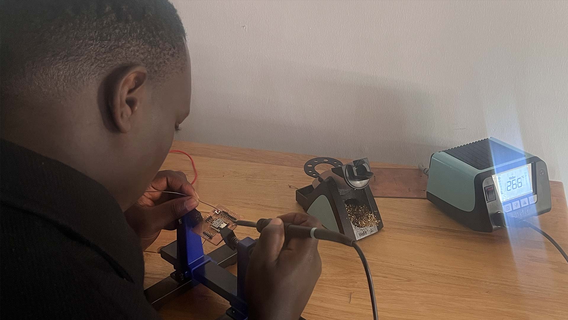
I started soldering with the main component which is microcontroller.
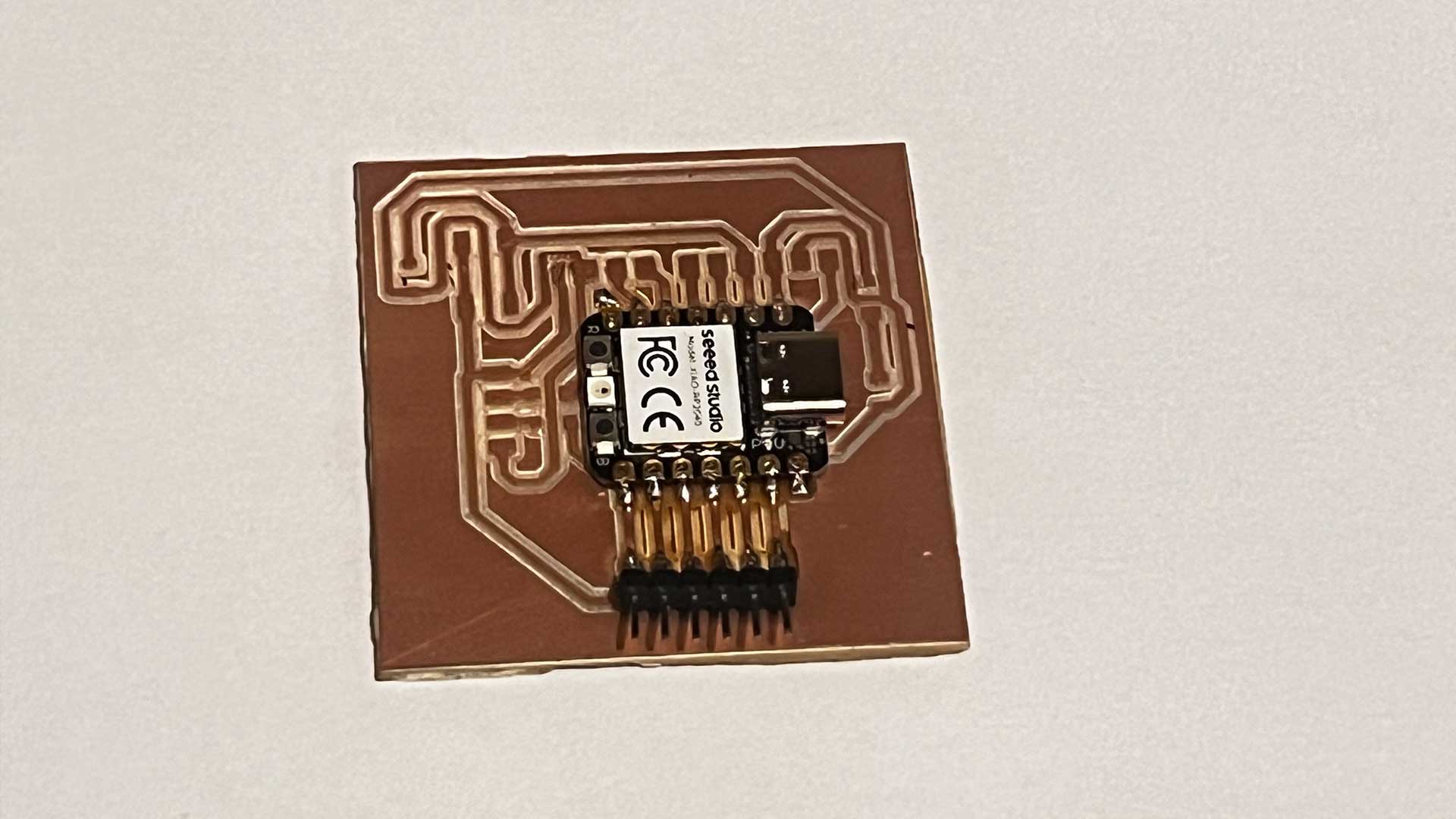
I soldered each component onto the board, ensuring secure connections.
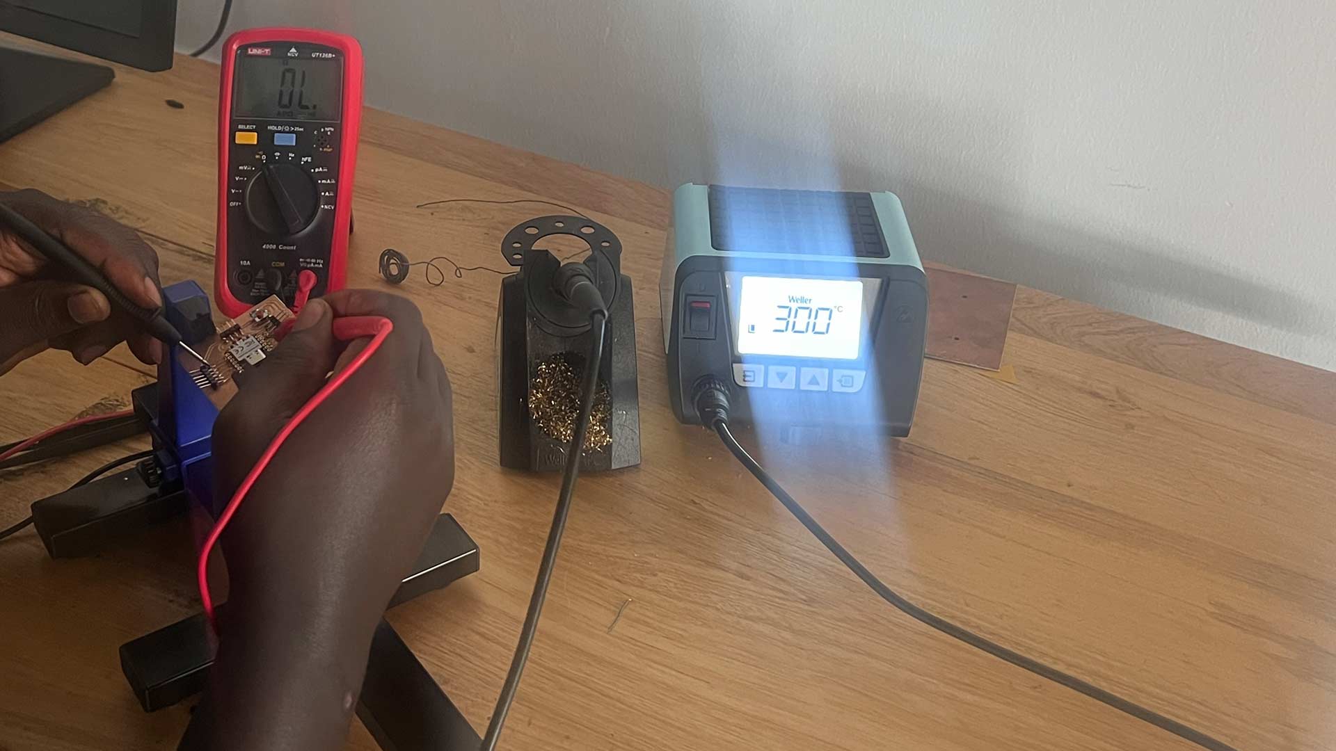
After soldering, I conducted thorough continuity tests to verify proper connections.
PCB Testing
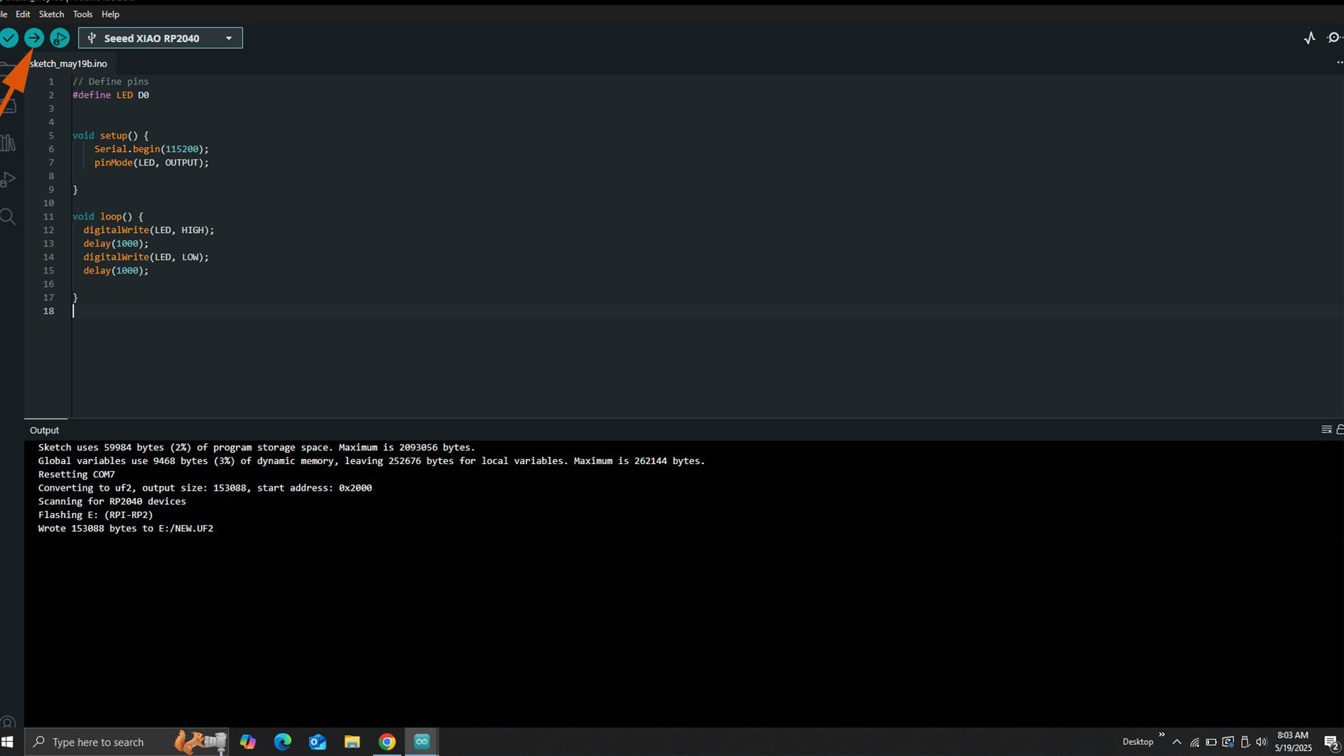
After soldering all components on the pcb, I wrote a simple script to lit LED so as to make sure pcb is functioning
To test the functionality of the PCB, I wrote a simple script using the Arduino IDE (Integrated Development Environment) a software application used to write, compile, and upload code to Arduino boards, which is compatible with various boards, including the Xiao RP2040.
        // Define pins
            #define LED D0


            void setup() {
                Serial.begin(115200);
                pinMode(LED, OUTPUT);

            }

            void loop() {
              digitalWrite(LED, HIGH);
              delay(2000);
              digitalWrite(LED, LOW);
              delay(2000);
            }
After, I complited the code.
Testing Outcome
The script successfully blinked an LED, confirming the PCB's functionality.
Download files
Here is the arduino file you can use to lit LED, testing PCB
PCB Edge cut Arduino code to test PCB