Final Project
BMI Calculator
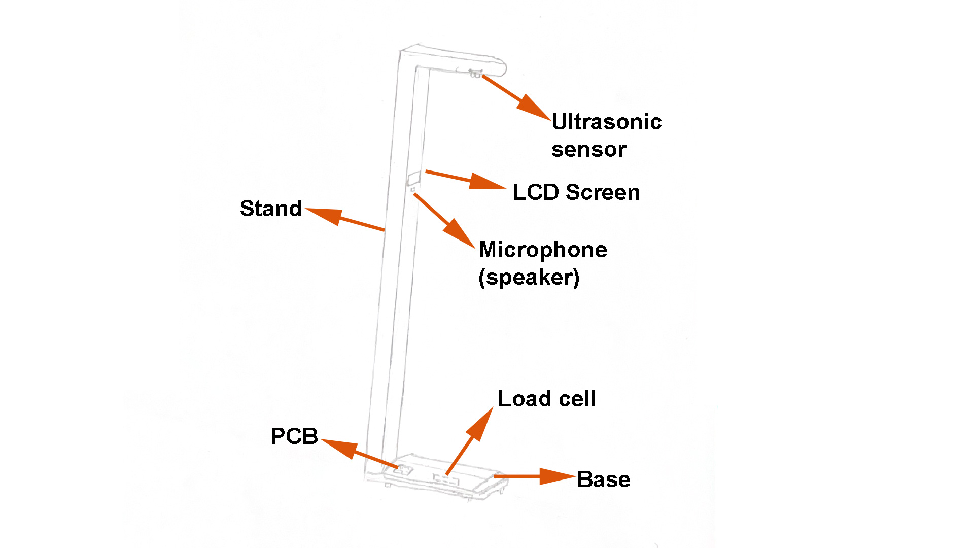
The BMI Calculator is an interactive device which designed to measure a person’s weight and height and then instantly compute their Body Mass Index (BMI). Its goal is to make health monitoring quick, accessible, and user-friendly for many people.
Why I chose this project?
Body Mass Index (BMI) is one of the simplest measurements used globally to assess the structure of a person's body. It gives an estimate of whether a person is underweight, normal weight, overweight, or obese. However, taking BMI traditionally involves the use of various devices — a scale for weight and tape or stadiometer for length — and manually calculating.
With the BMI Calculator, I aimed to design one, self-contained device that allows individuals to easily and rapidly measure their weight and height and instantly computes the BMI and shows the output clearly. It also Offers a simple user interface, allowing it to be used in schools, gyms, clinics, or even at home.
Project goal
My goal is to build, construct, and code an integrated system that:
- Scales the individual with a load cell sensor
- Measures height with an ultrasonic sensor.
- Inputs user input through a keypad.
- Displays the calculated BMI and status on an LCD screen.
1. List of materials
| Items | Quantity | Price/unit | Total price | Link |
|---|---|---|---|---|
| Load cell (200kg) | 1 | 39.00 $ | 39.00 $ | amazon.com |
| HX711 Load Cell Amplifier | 1 | 3.50 $ | 3.50 $ | amazon.com |
| HC-SR04 Ultrasonic Sensor | 3 | 3.50 $ | 3.50 $ | amazon.com |
| 9mm MDF board | 1 | 25.00 $ | 25.00 $ | Local hardware store |
| 40x40 metal tube | 1 | 6.00 $ | 6.00 $ | Local hardware store |
| LCD Screen | 1 | 9.96 $ | 9.96 $ | amazon.com |
| Keypad (4x4) | 1 | 2.50 $ | 2.50 $ | amazon.com |
| Total | 89.46 $ |
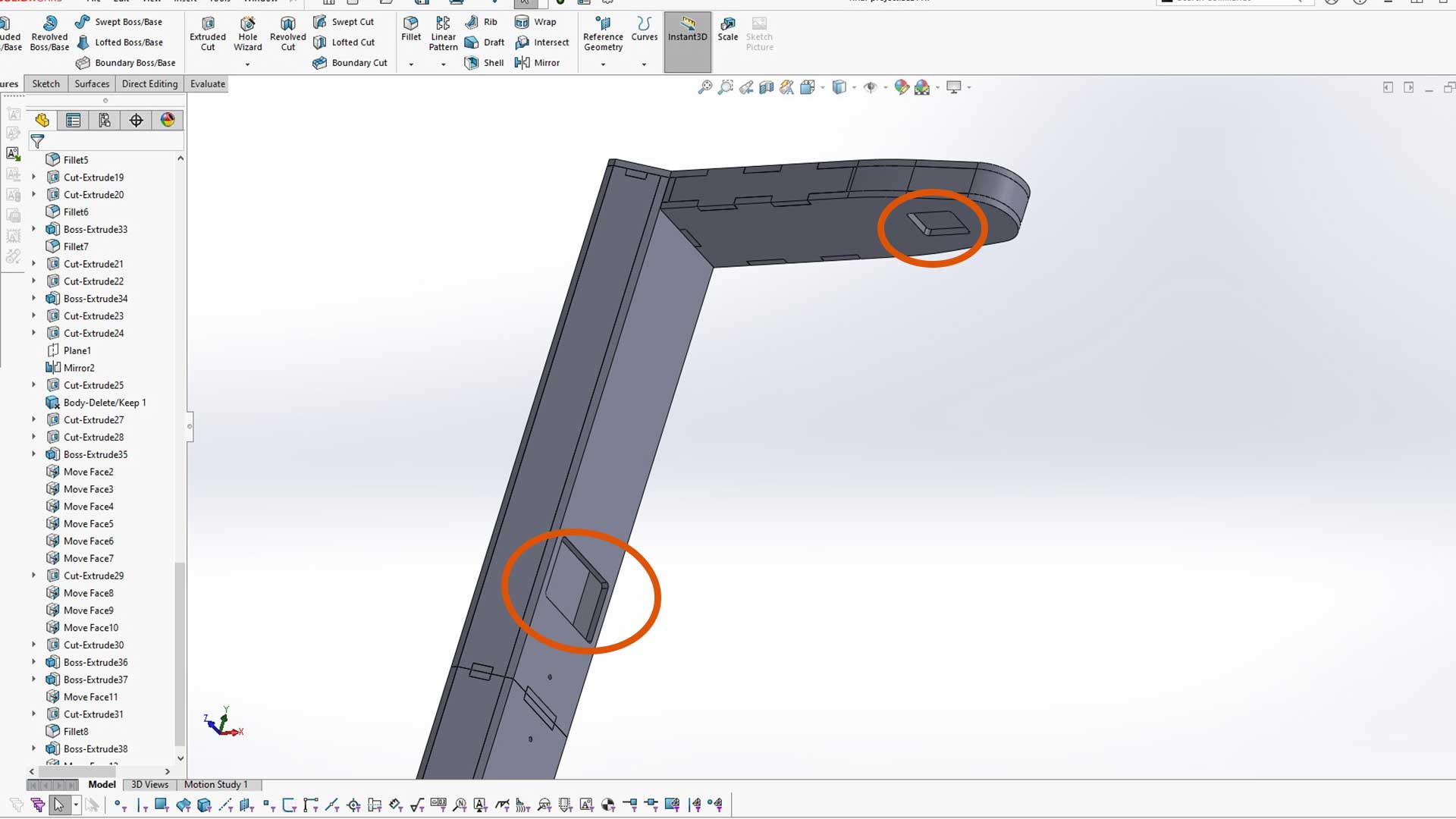
2. Final project design
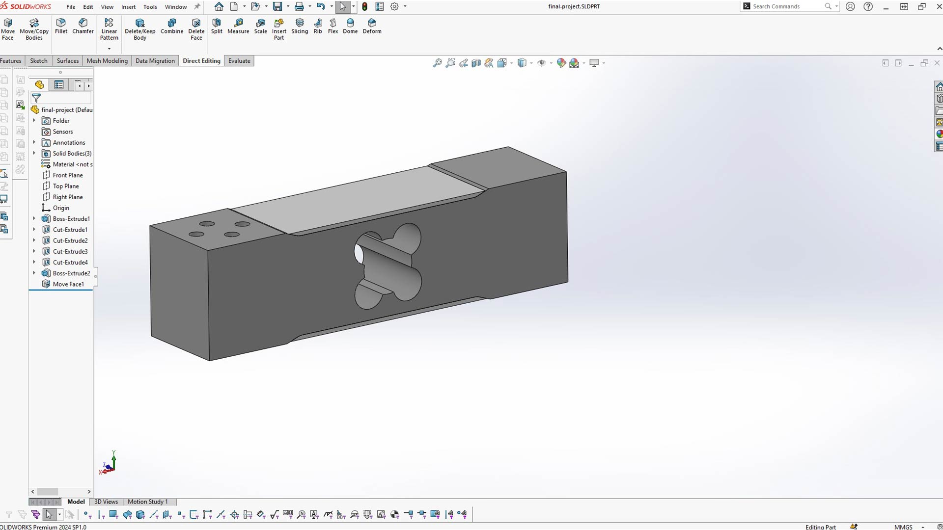
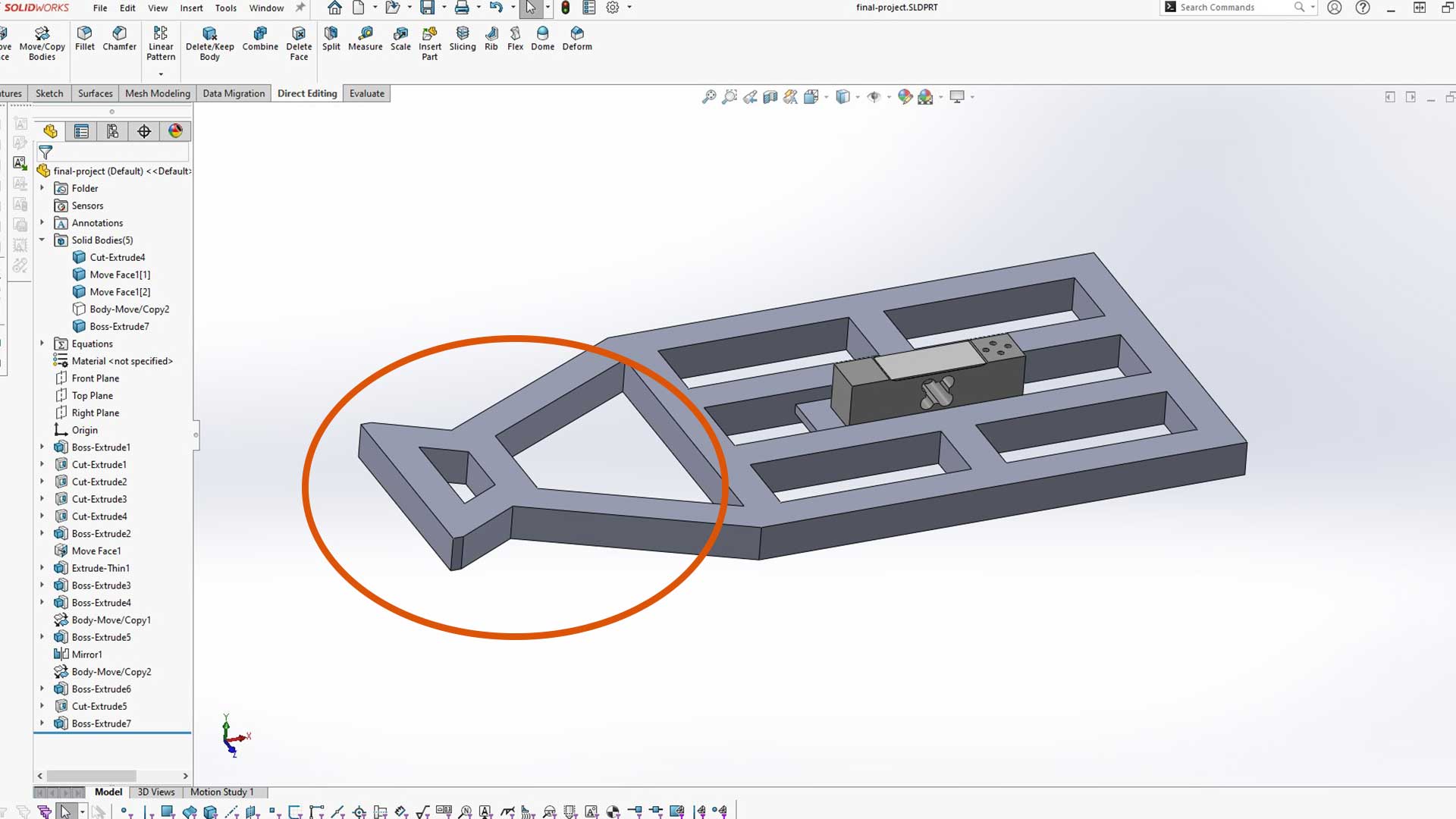
I started with the design of load cell. Since the structure will revolve around it, I am using SolidWorks multibody method to make the process seamless.
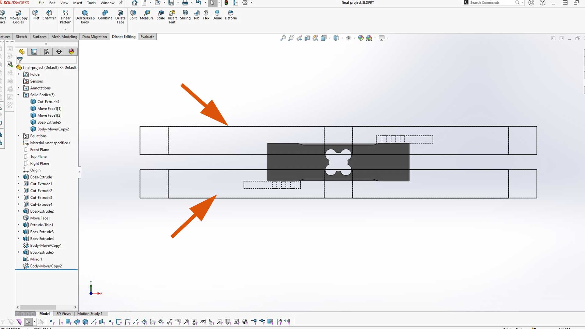
I then designed (metal) frame around the load cell.
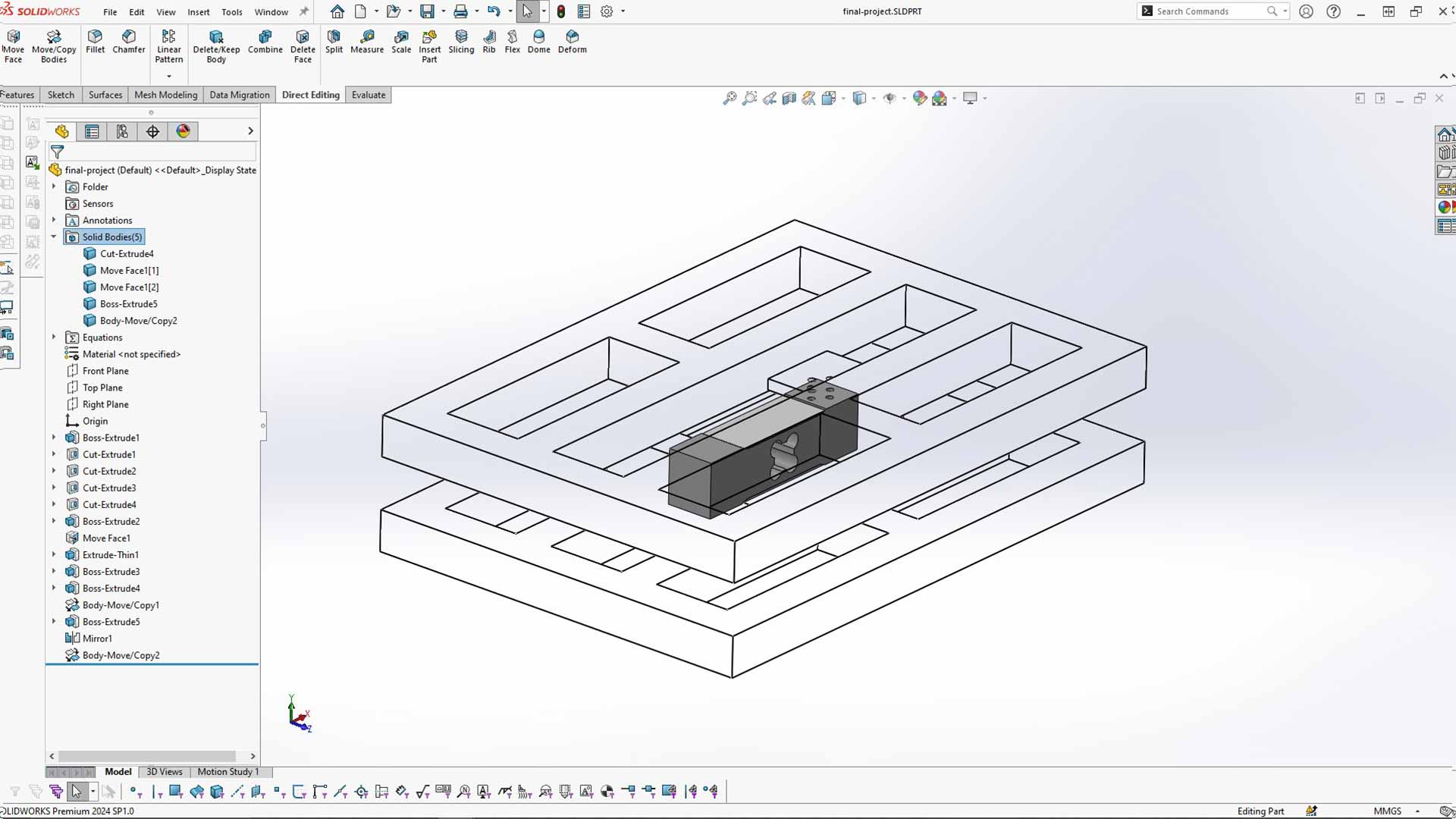
Since the top and bottom frame must not touch each other, however it is not necessary to keep them far apart. Therefore, I reduced the distance between the. I used move mody method.
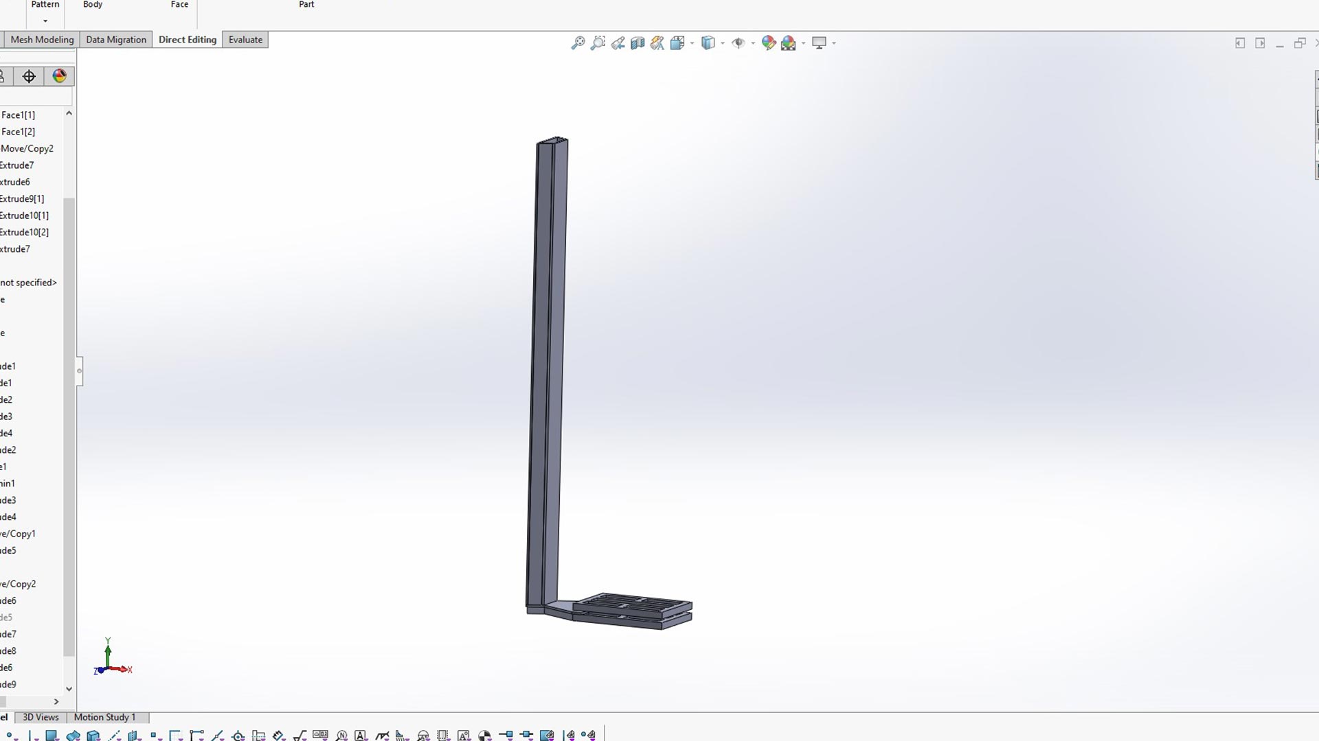
At the bottom frame, I extended it by adding a frame to support the vertical stand.
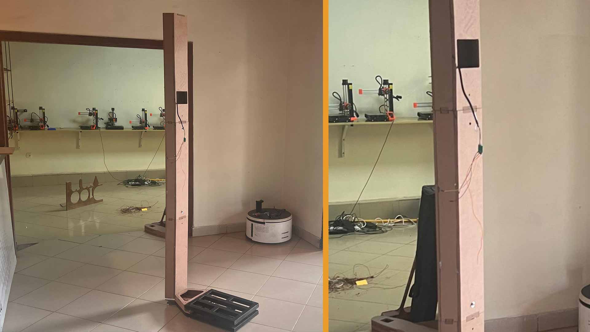
I then added vertical stand of 2.1m tall.
Since this stand is tall, I splitted it into 3 sections. This not only easy the assembly, it also ease its packaging and transportation
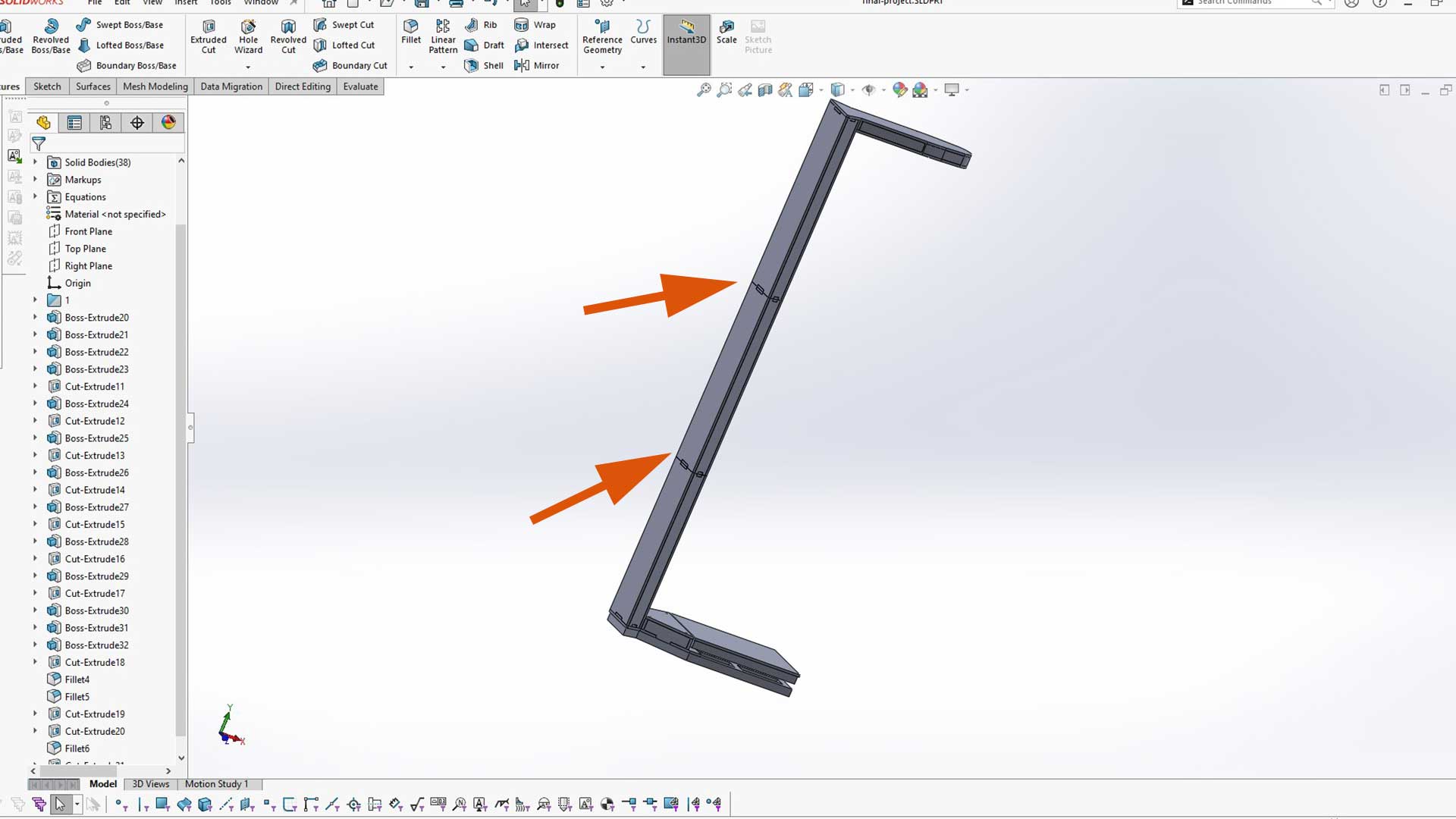
I then added support structure inside. This will also guide me during assembly.
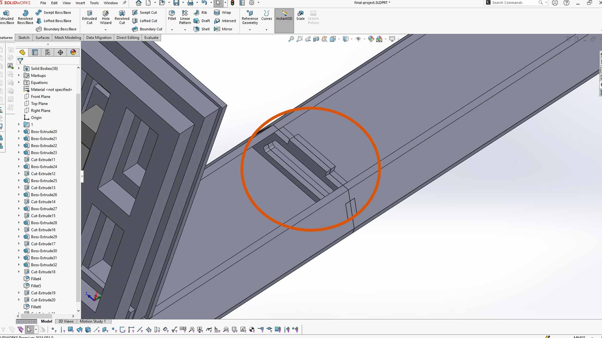
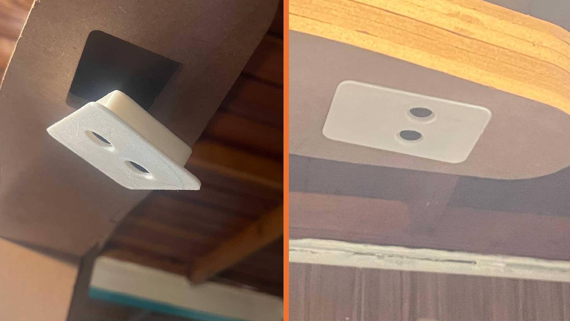
I then added cutout for screen as well as that of Ultrasonic Sensor
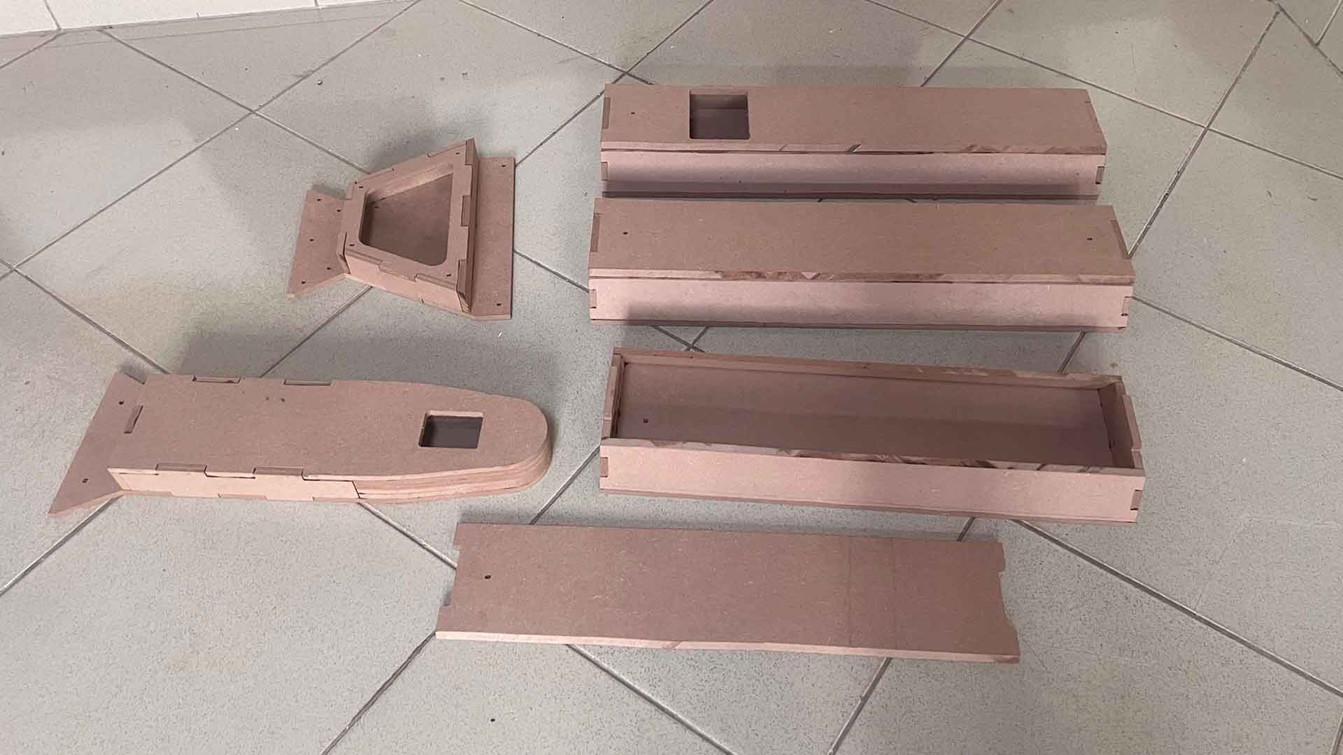
Cutting parts on CNC Machine
I imported all dxf files into VCurve and rearranged them accordingly.
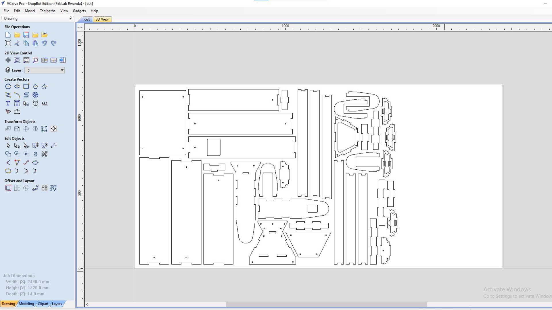
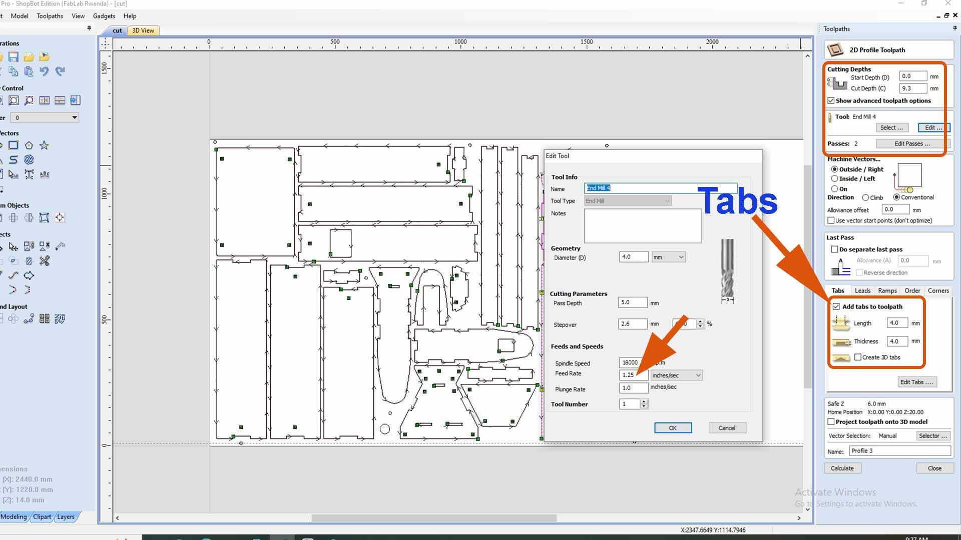
Since some parts are really small, I added tabs to hold them. This is to avoid parts from displacing which may break tool as well faults (inaccuracy) of output.
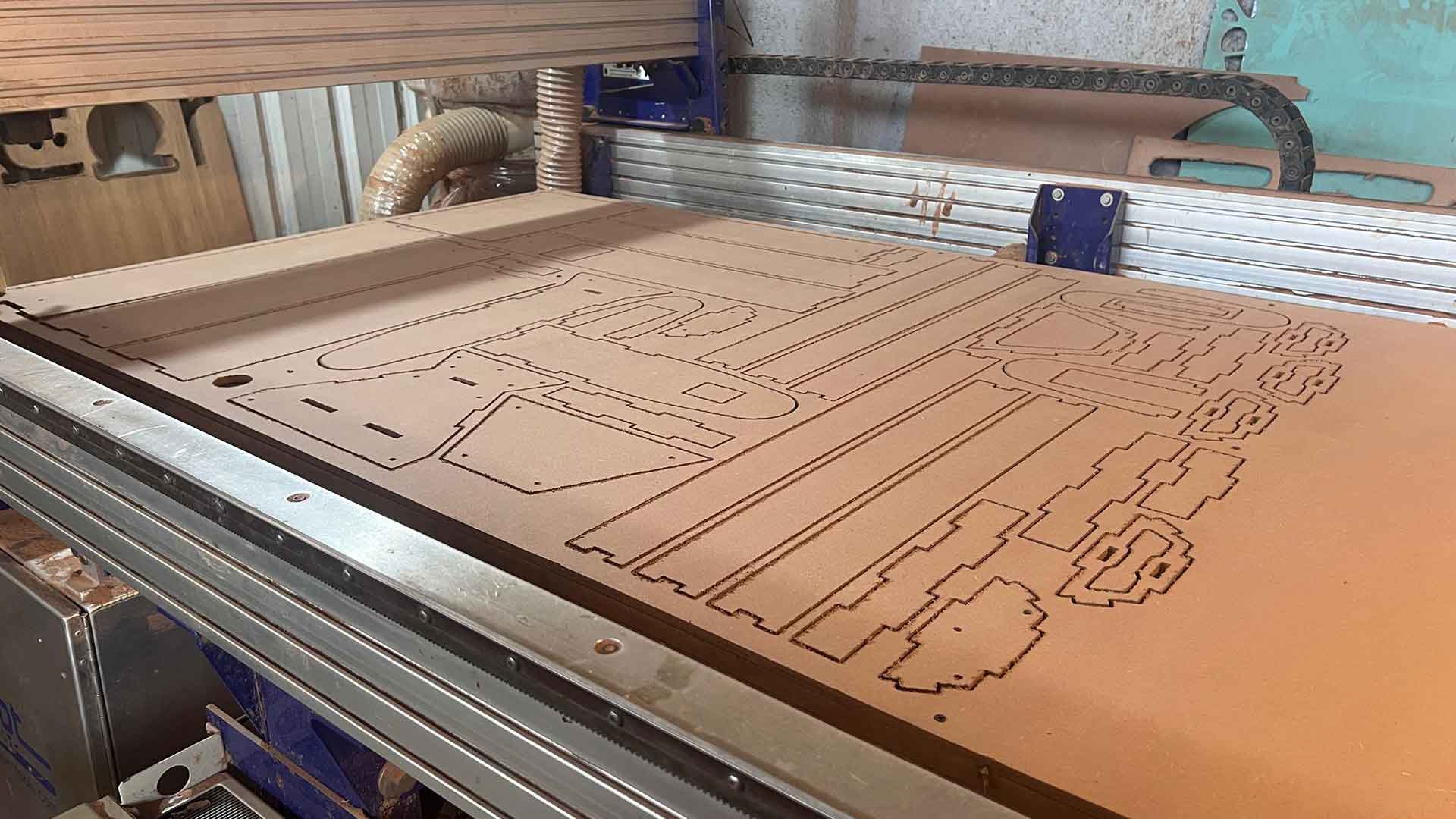
CNC done cutting
Angle cutting
Sone parts needed to be cut on angle. Therefore, I used circular saw to cut them.
Welding frame
For welding, I cut all pieces sized according to the dimensions.
I cut the shape (template) of frame from MDF to ease the alignment.
3D Printing of some parts
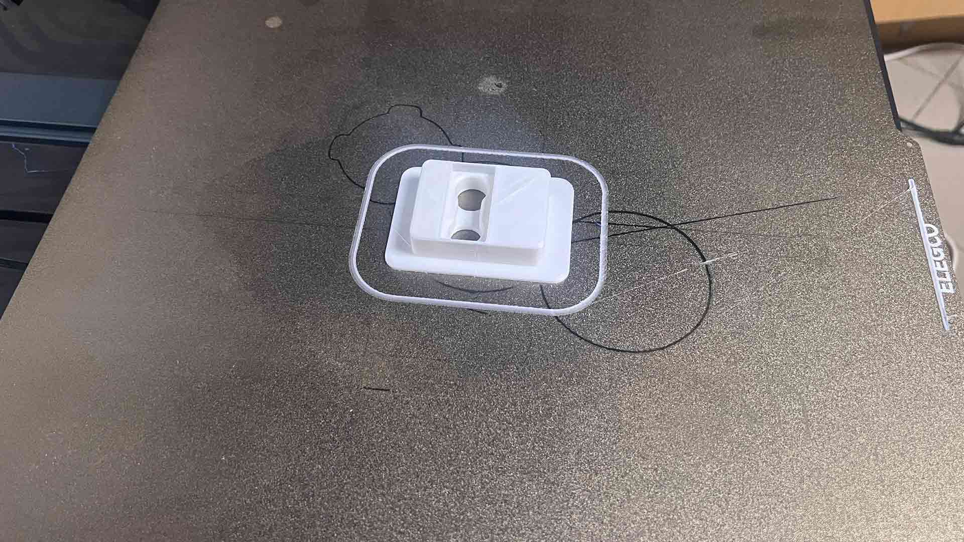
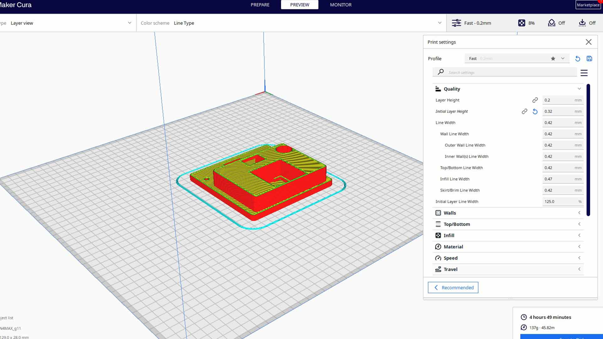
I started with ultrasonic holder. I used ultimaker cura for slicing.
Printing done. Success!
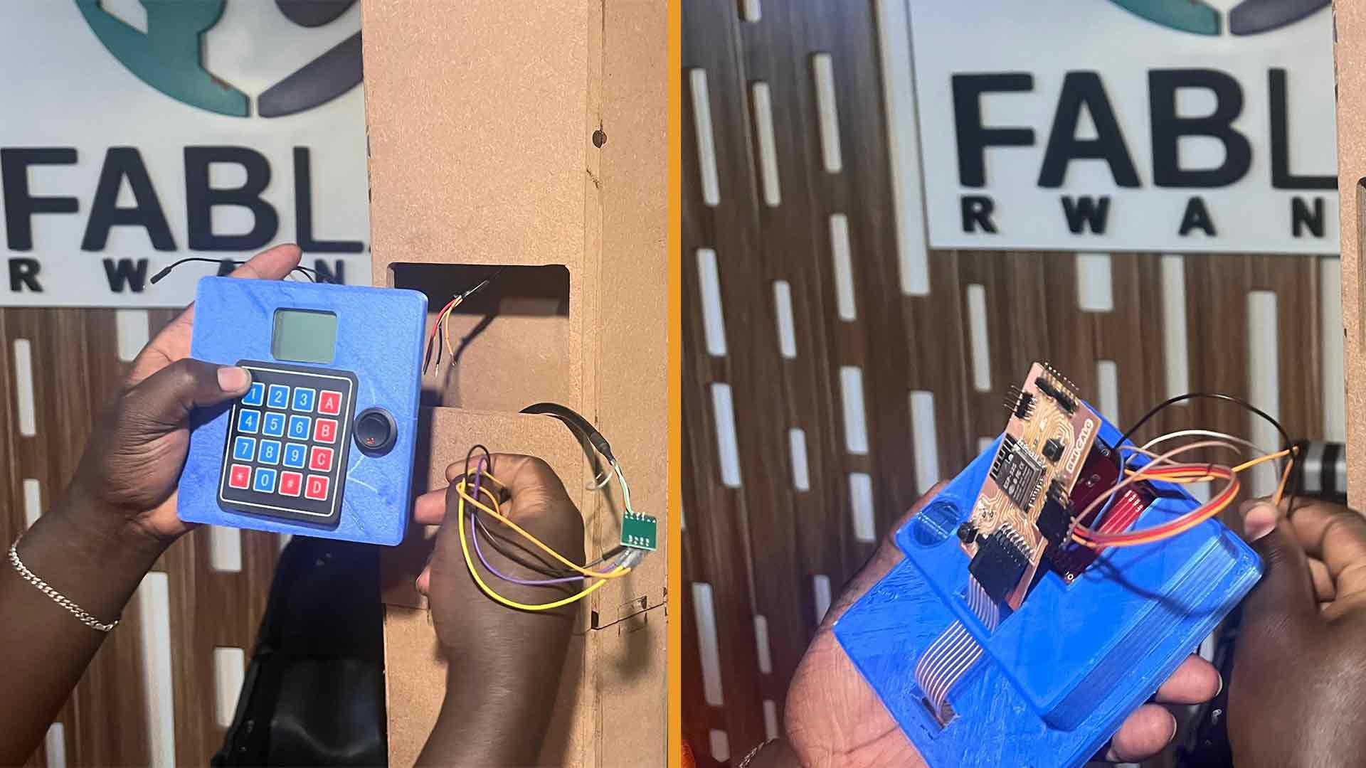
Next I printed screen holder. This also hold keypad, power button and pcb board.
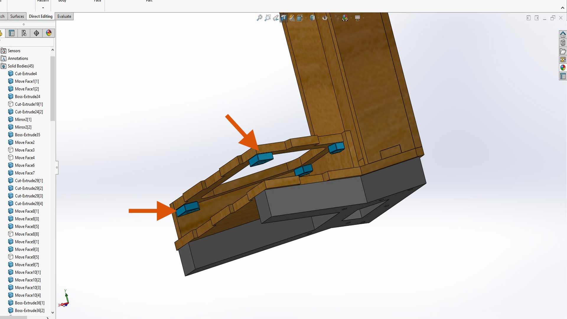
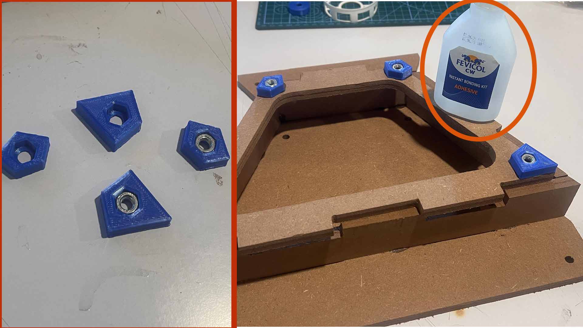
In other to make assembly and disassembly of sections doable, I added nuts holded by 3D printed parts. I used glue for their assembly.
Assembly of structure
Assembly was straight forward since I tested fitting before.
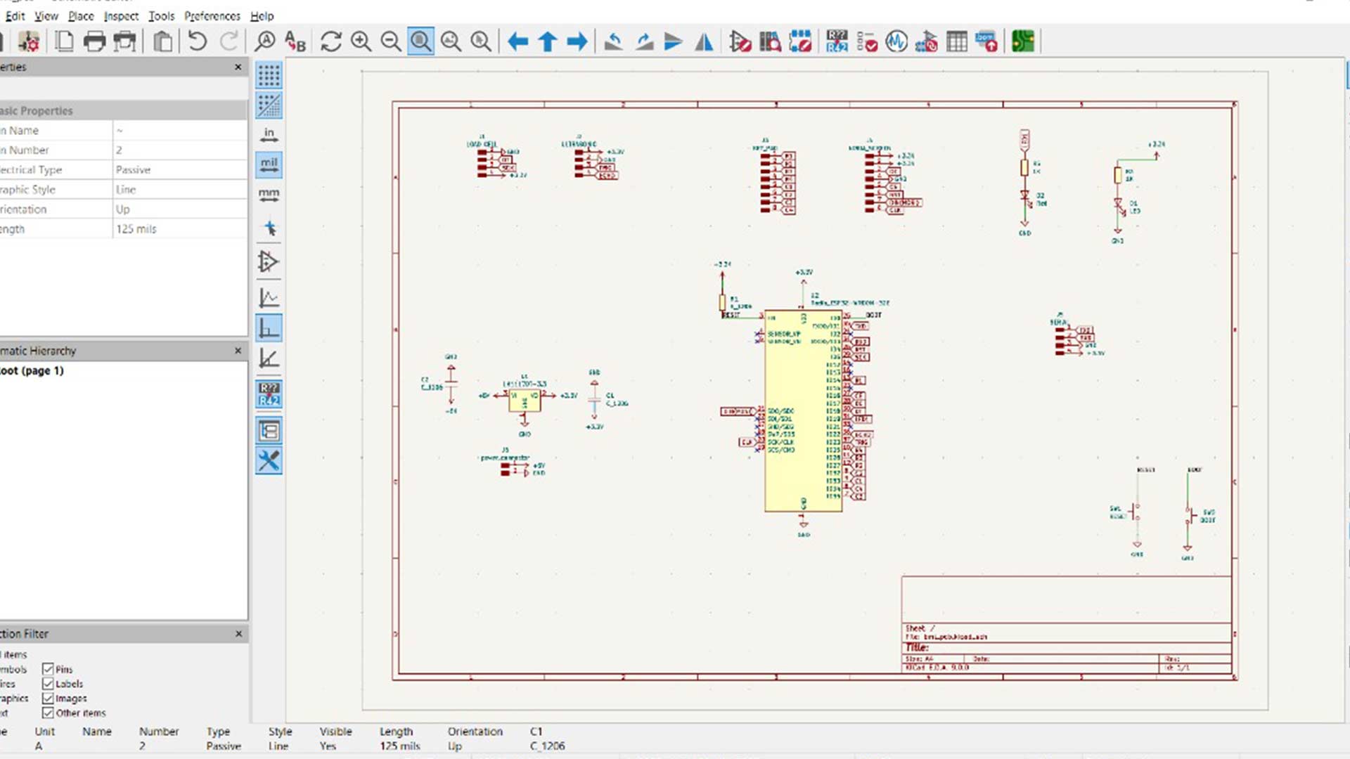
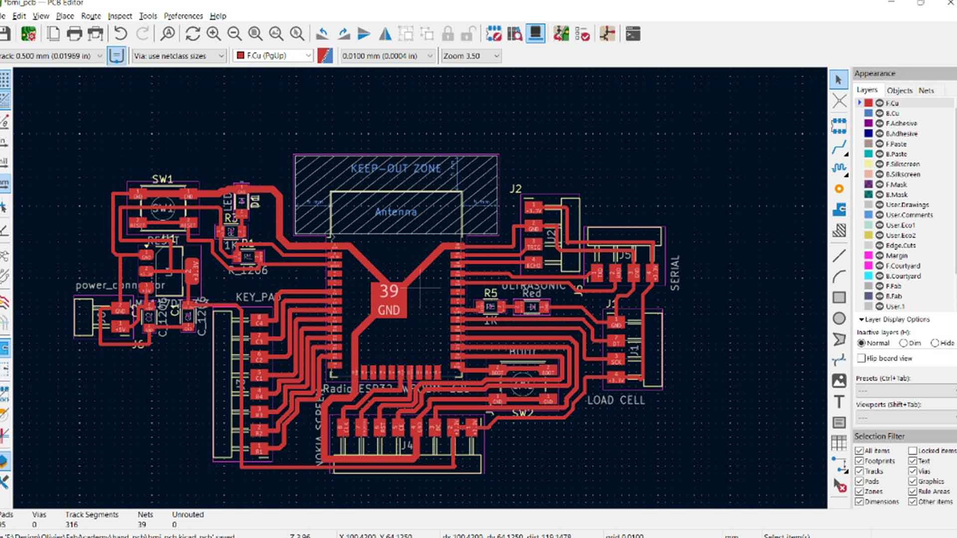
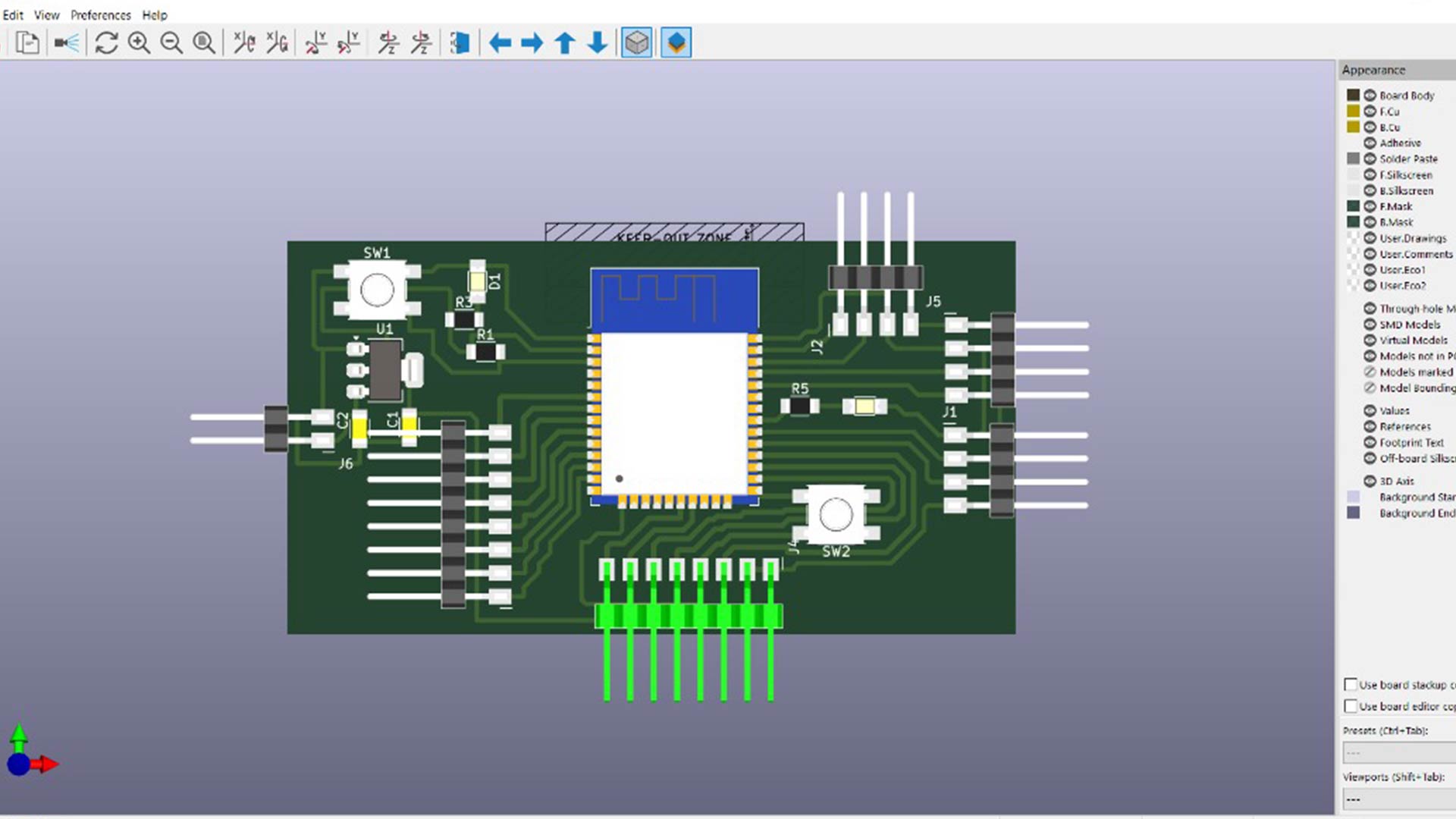
Electronic design
To design PCB, I used KCad
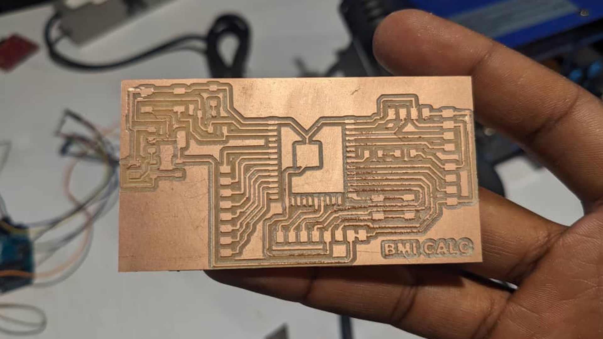
PCB Milling
To start off milling, I used modsproject.org to generate gcode
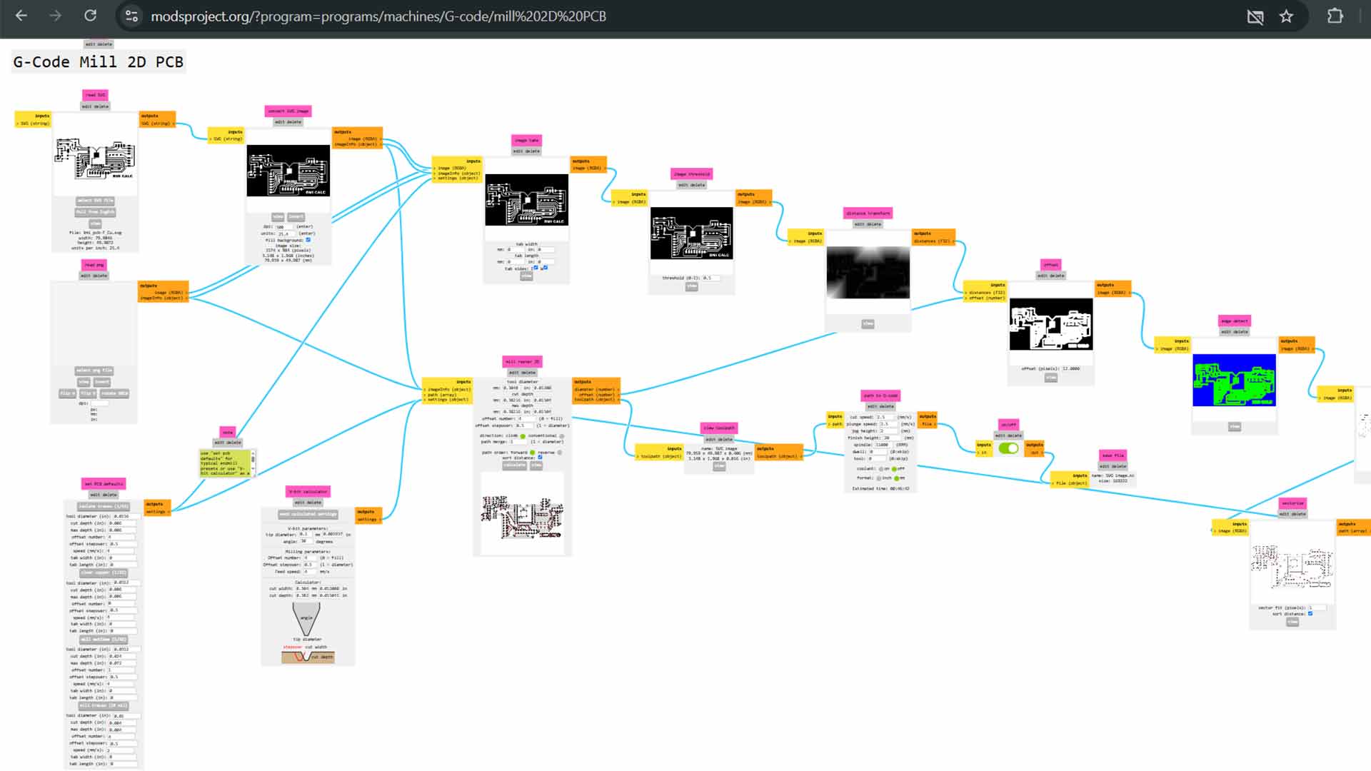
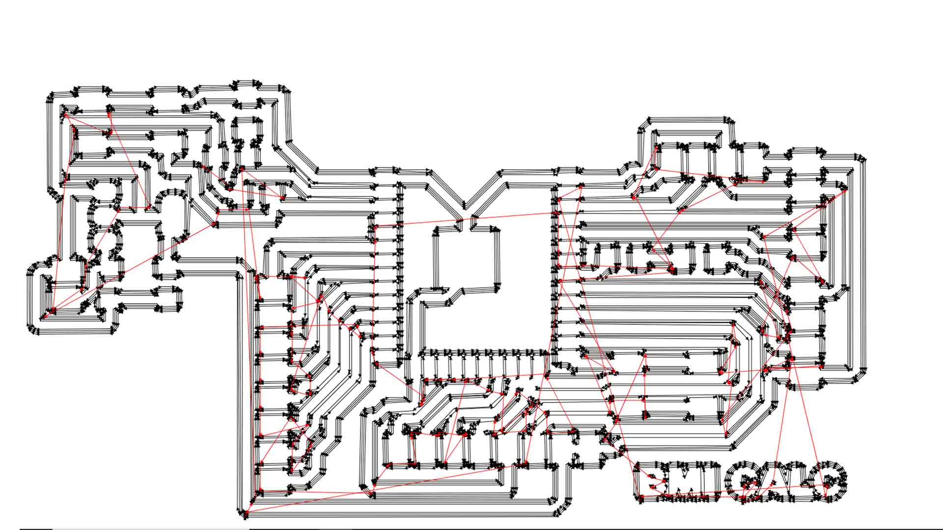
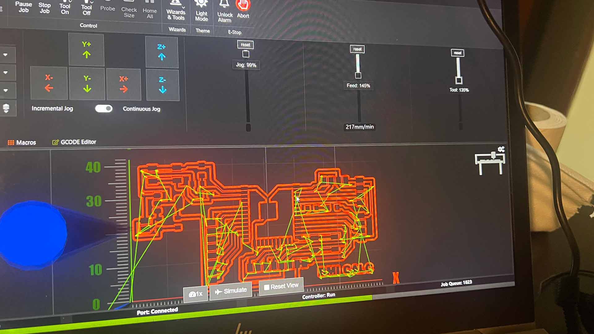
Then I used PCB milling machine to print it. I used openbuilder Program for machine control.
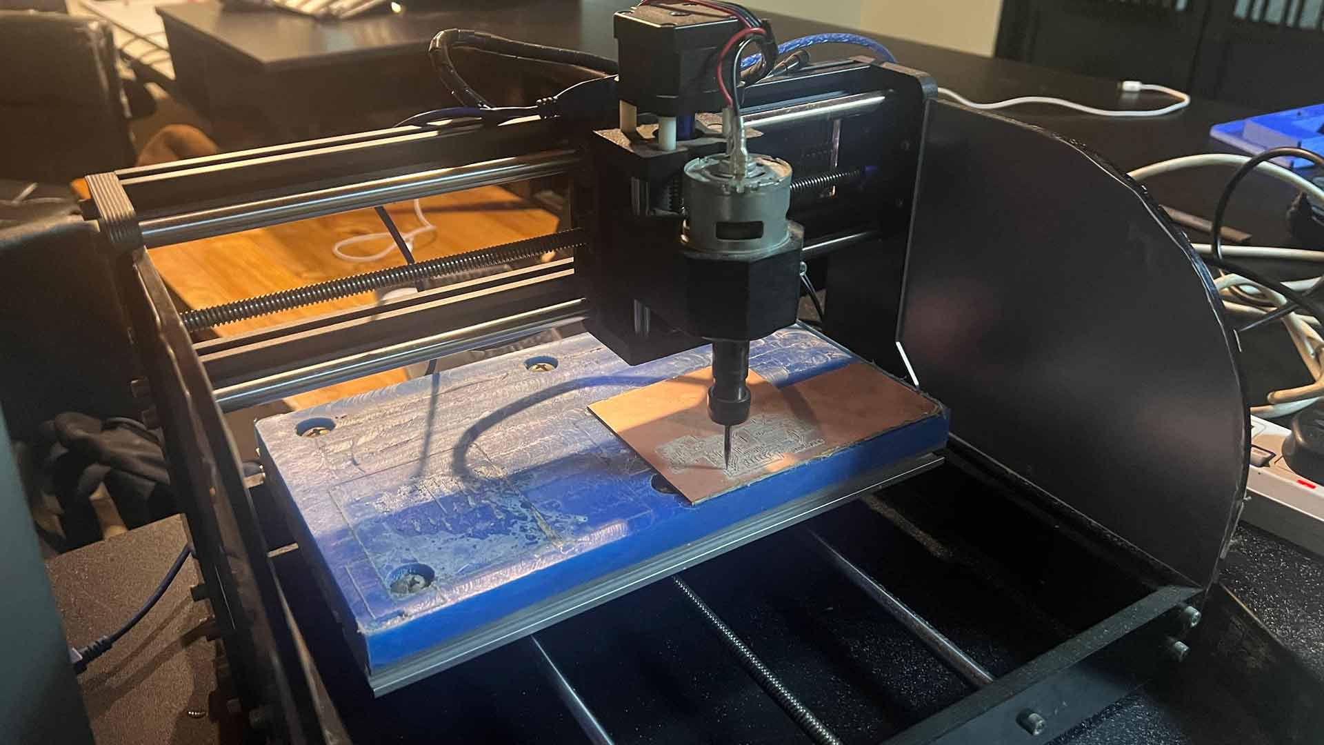
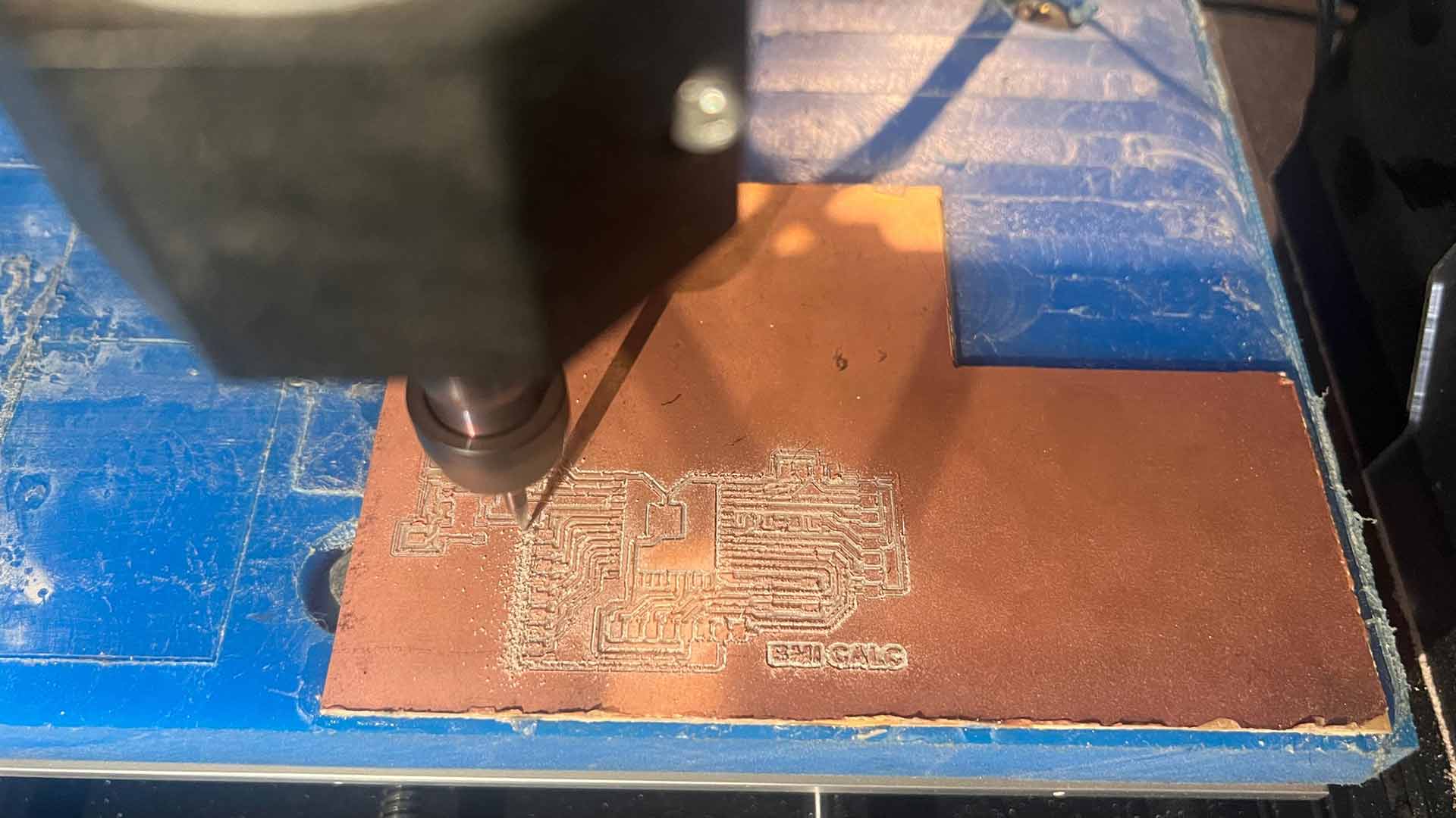
Result
Soldering
I soldered EPS-32S microcontroller, extension pins and other components.
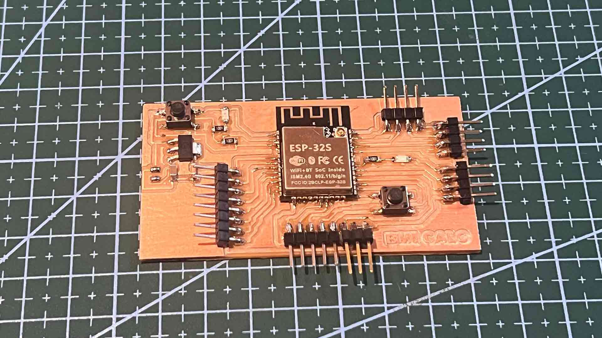
I then soldered HX711 Load Cell Amplifier
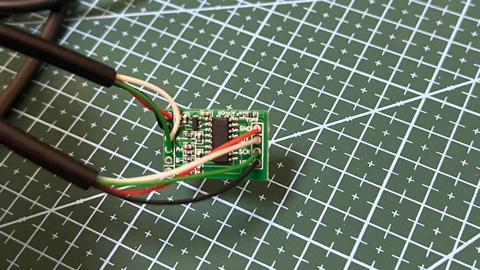
At each wire, I also soldered jump wires to make I can plug and unplug divices easily.
Assembly all sections
I started by assembly load cell with the stand. This is one of the crucial process. The load cell need to be as rigid as possible relative to its frame.
I followed up with other sections
I then used bolts for tightening. I also inserted load cell wire along the way.
Next I assembled the top part with Ultrasonic Sensor already installed. After I added its cover.
Programing
I used arduino IDE for programming
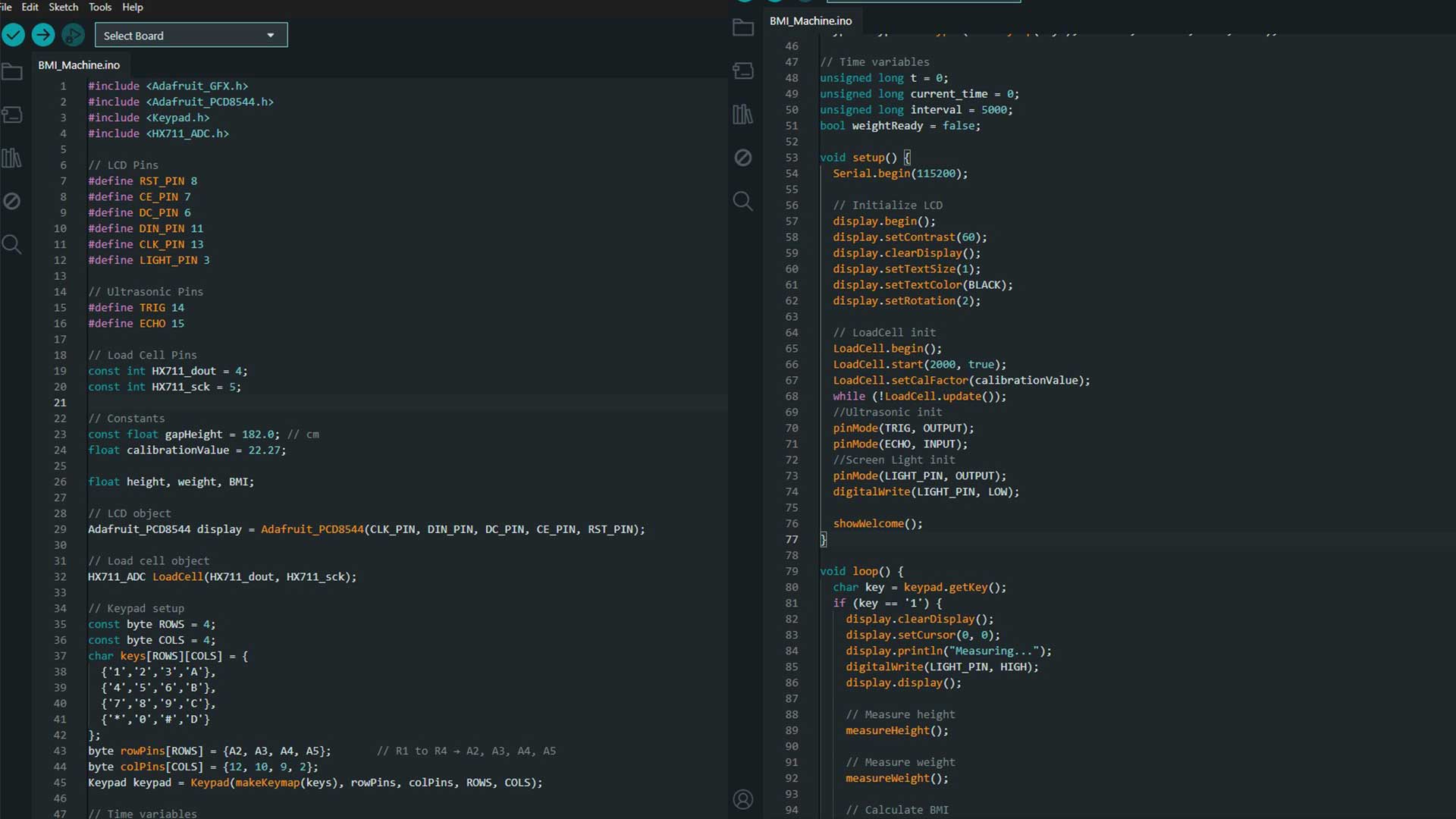
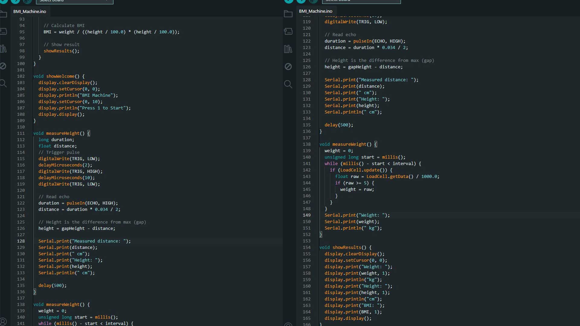
Note: Code I used can be found at the bottom of this page in download section.
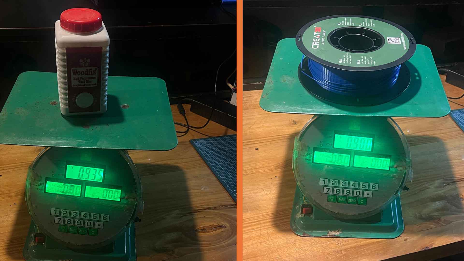
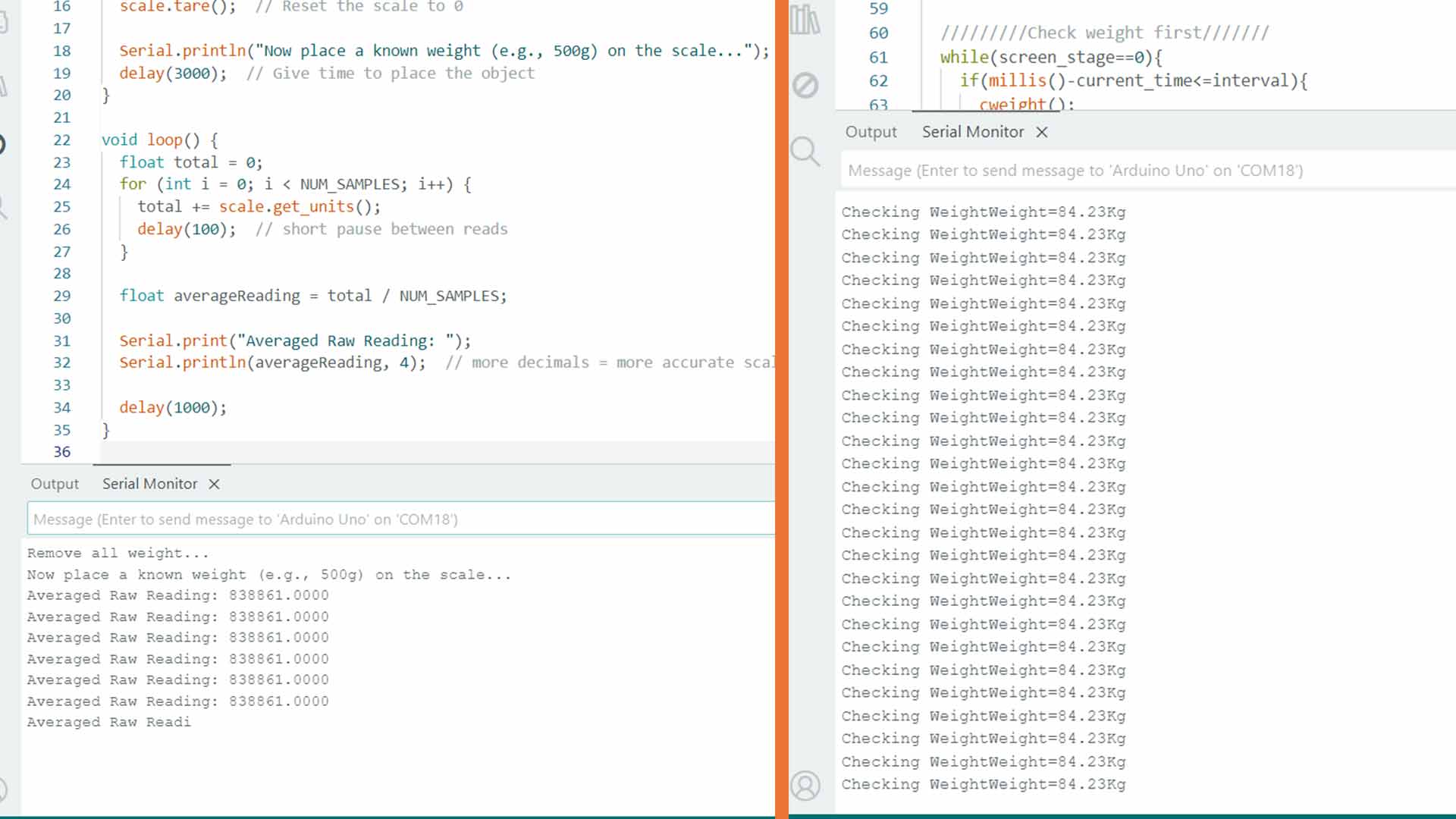
Calibration
One challenge I faced was to calibrate the load cell. Previously it was reading offscale values.
Therefore, I used kitcken scale to measure few items accurately. Then I used them to adjust scale factor (calibrate load cell).
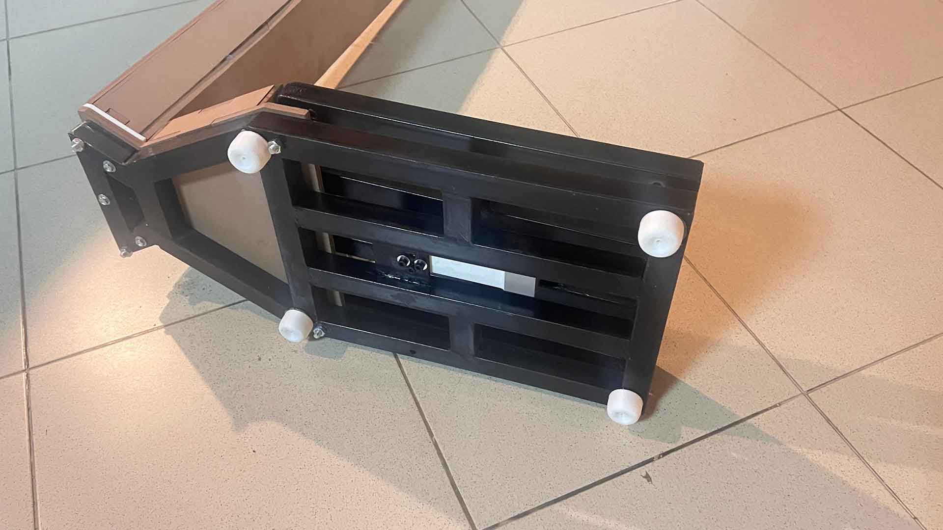
At the bottom, I added 3D printed stand. Because of bolts and nuts petrouding undeerneth, the entire structure was not standing upright.
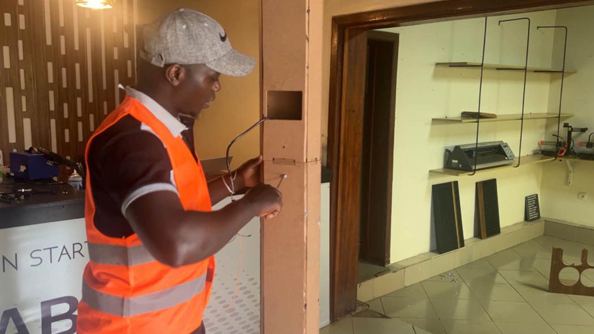
Testing
I then assembled everything together and then connected to power. The power is 5V.
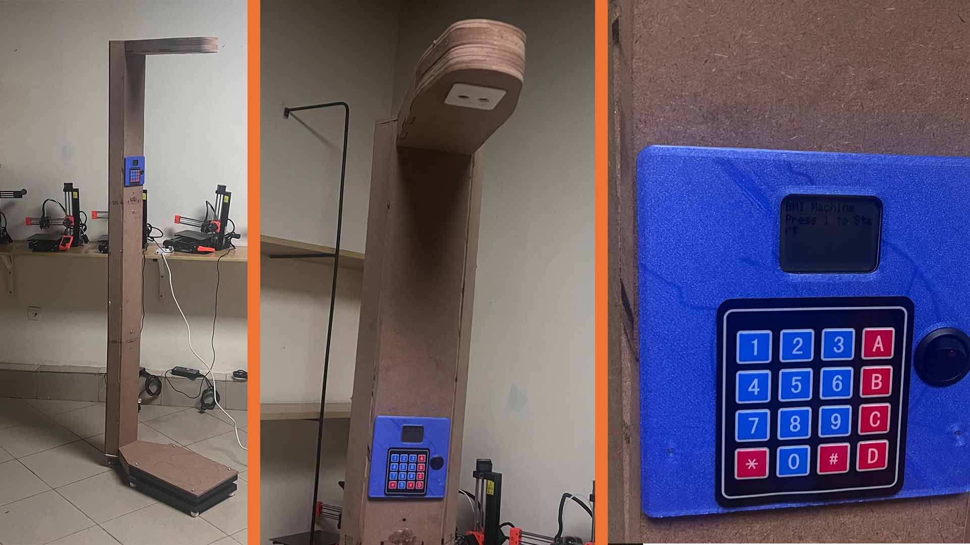
Powering on machine.
Machine measuring one of my collegue
Download files
There are files including CAD file, pcb and arduino code I used.
CAD files PCB Design Arduino code