Assignment Brief:
- Write an application that interfaces a user with an input &/or output device that you made
- As a group, Try out and compare multiple tools for interfacing with devices.
Lets begin
I started this weeks major work from, referring to the documentation pages of Siddharth Himanshi and Jesal sir. The concept was very knew to me so revised some of the basic stuff that came up during the lecture.
What are Interfaces?
Interfaces refer to the connection points or boundaries where two systems, components, or entities interact. In computing, an interface defines how different software components communicate through a set of rules or functions—without needing to know the internal code or structure of each other.
What does API stand for?
API stands for Application Programming Interface. It’s a specific type of interface that defines how software programs interact. It provides developers with a standard way to request data or services from another application or platform.
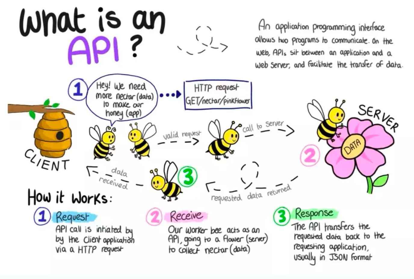
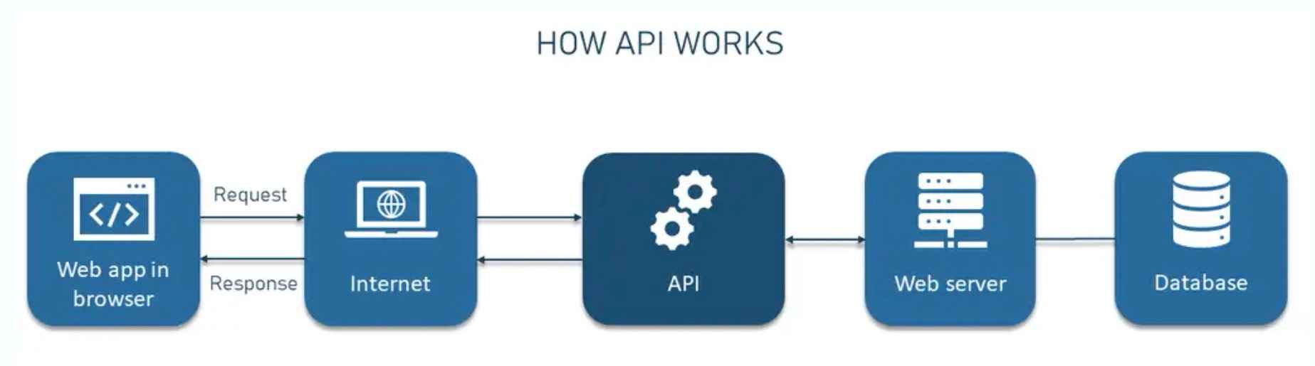
What is an API?
An API is a set of defined methods and protocols that allows software components to talk to each other. APIs make it possible for one program to access features or data of another without needing to understand its internal code—similar to how apps use third-party services (e.g., weather data, maps, payments).
Other Terminologies are:
API Analogy: An API works like a waiter, passing your request to the server (kitchen) and bringing back the
response.
What does an API do? It acts as a secure middleman between client and server, handling requests and
responses.
Security and Access: APIs control data access based on user authentication, keeping backend systems protected.
Processing using the Xiao RP2040
Processing is a Java-based programming language and environment primarily used for creating visuals and sketches. It is ideal for developing interactive graphics and offers libraries that support not only graphics but also sound and video processing.
In the context of APIs, Processing refers to handling and transforming data between requests and responses. It involves taking the input (like data from a user or device), processing it on the server, and then sending the result back to the client through the API.
You can download the software for here: Processing website.
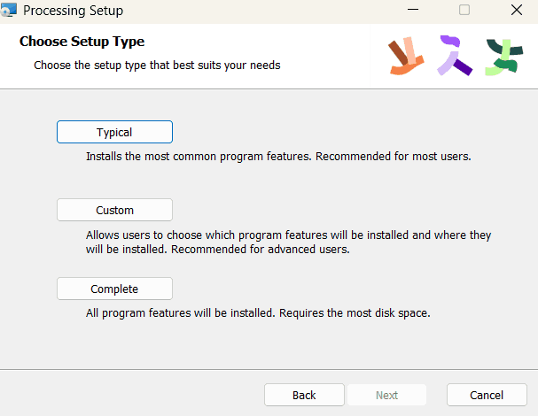
Click download and install
_3_11zon.png)
During this set up pint, select typical.
Mouse to led blink
I started by looking at Siddharth's document. The task was to create a circle, and then code the RP2040 so that when the mouse clicks within the circle, the built-in RGB LED on the Xiao lights up. The process for which was:
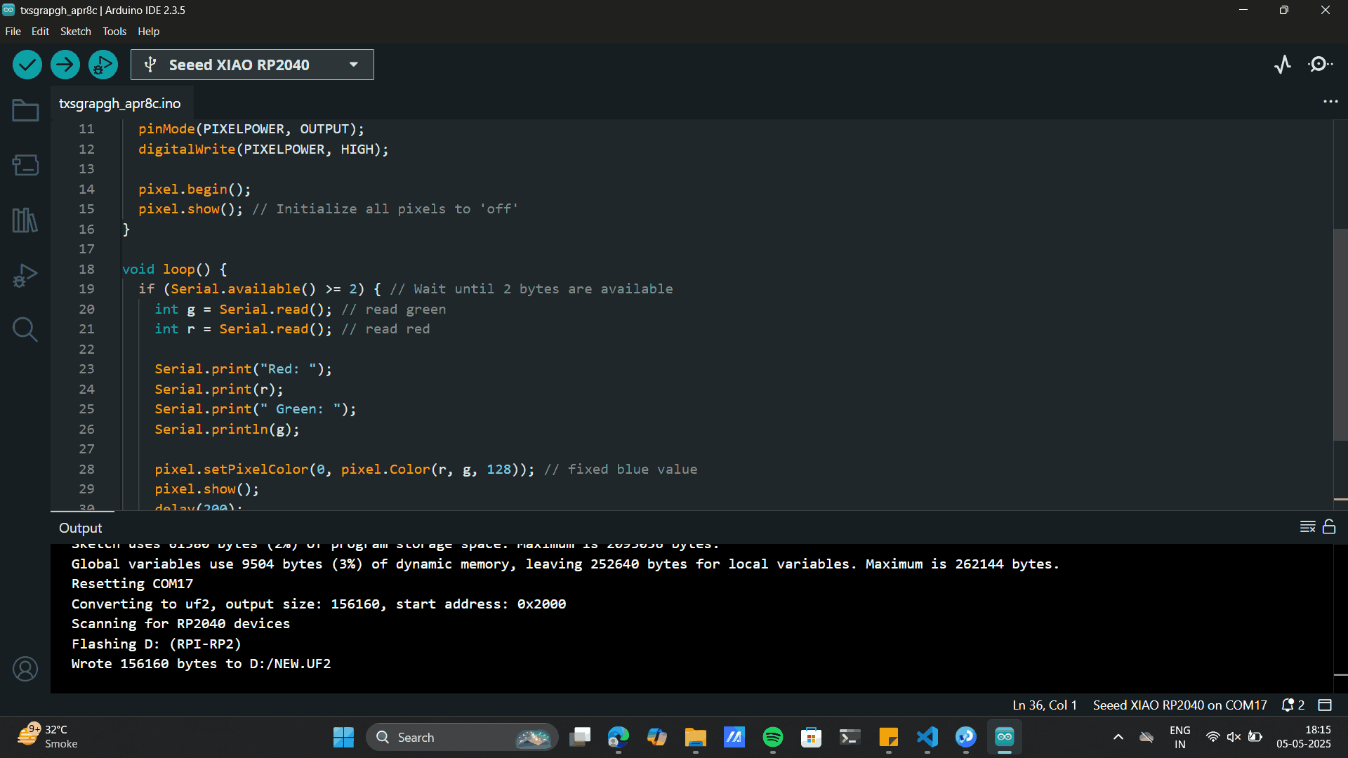
1) Code for Ardiuno IDEInstall the library if not installed yet
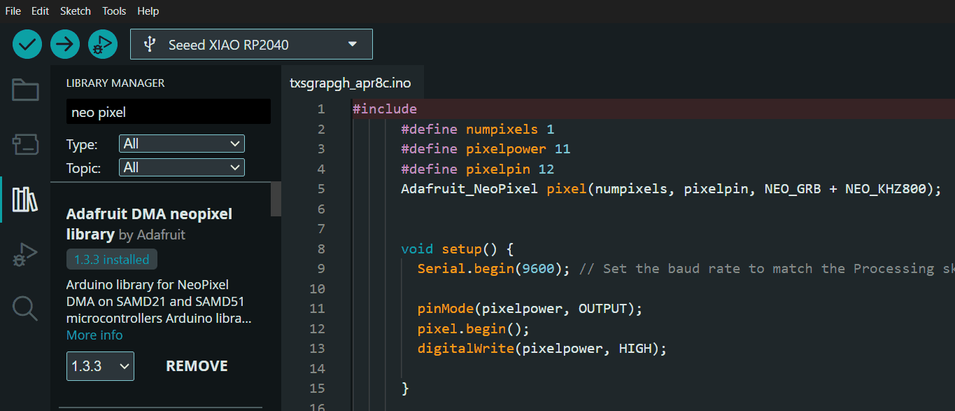
Upload the below code to Aurdino IDE
            #include

                #define NUMPIXELS 1
                #define PIXELPOWER 11
                #define PIXELPIN 12

                Adafruit_NeoPixel pixel(NUMPIXELS, PIXELPIN, NEO_GRB + NEO_KHZ800);

                void setup() {
                  Serial.begin(9600); // Set baud rate to match with Processing or Serial Monitor
                  pinMode(PIXELPOWER, OUTPUT);
                  digitalWrite(PIXELPOWER, HIGH);

                  pixel.begin();
                  pixel.show(); // Initialize all pixels to 'off'
                }

                void loop() {
                  if (Serial.available() >= 2) { // Wait until 2 bytes are available
                    int g = Serial.read(); // read green
                    int r = Serial.read(); // read red

                    Serial.print("Red: ");
                    Serial.print(r);
                    Serial.print(" Green: ");
                    Serial.println(g);

                    pixel.setPixelColor(0, pixel.Color(r, g, 128)); // fixed blue value
                    pixel.show();
                    delay(200);

                    pixel.setPixelColor(0, pixel.Color(0, 0, 0)); // turn off
                    pixel.show();
                  }
} Processing IDE interface
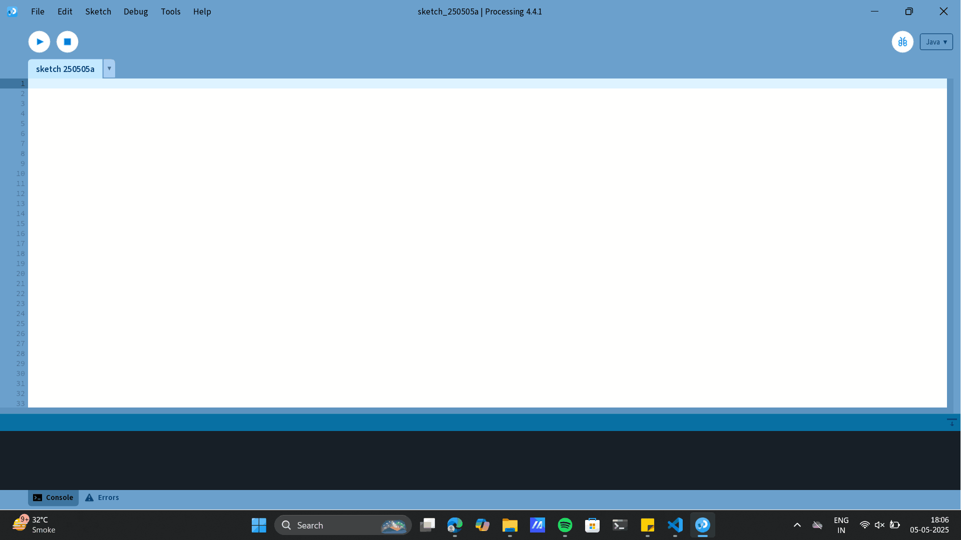
Upload the below code to Processing IDE
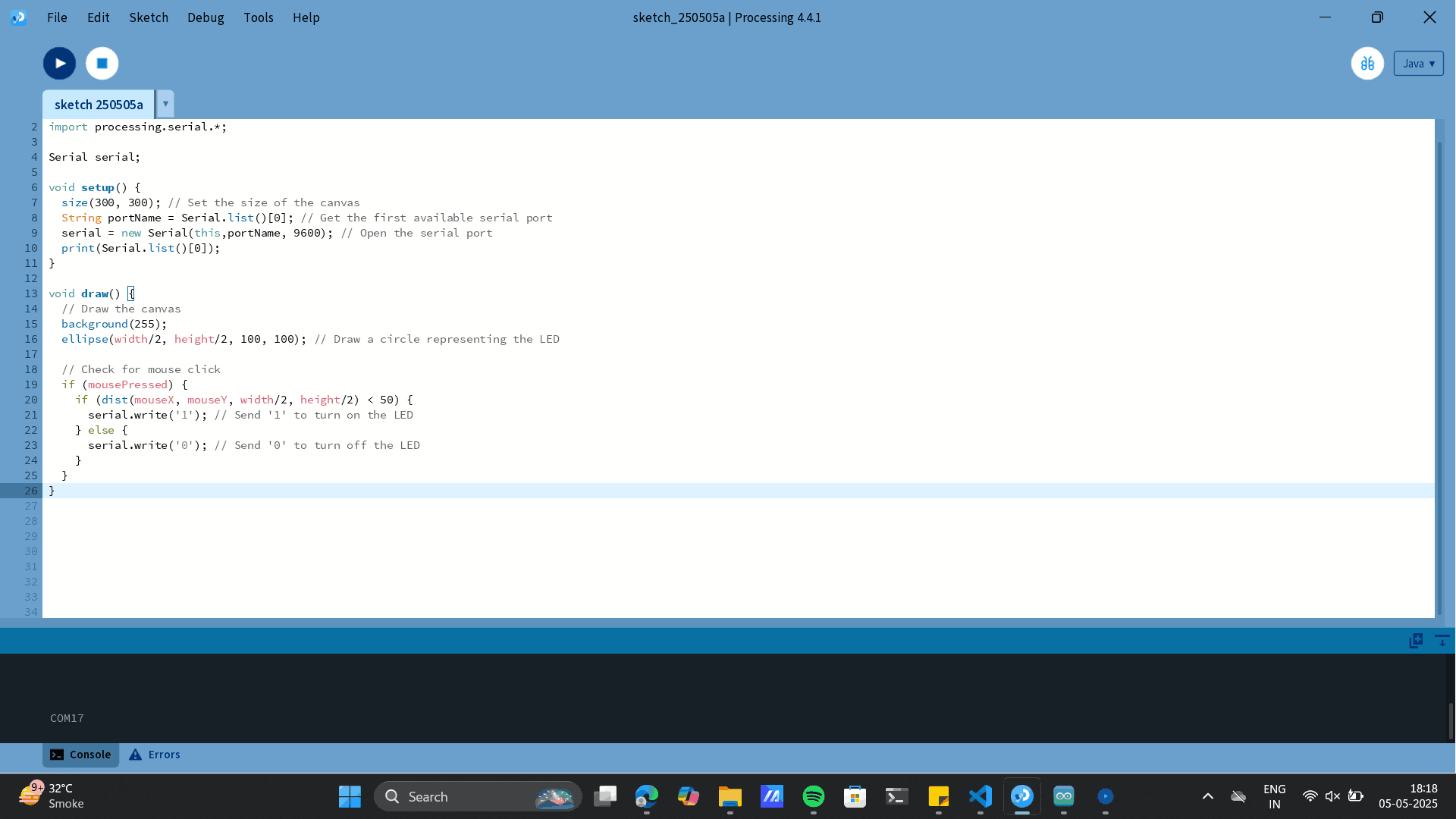
                    import processing.serial.*;

Serial serial;

void setup() {
  size(300, 300); // Set the size of the canvas
  String portName = Serial.list()[0]; // Get the first available serial port
  serial = new Serial(this,portName, 9600); // Open the serial port
  print(Serial.list()[0]);
}

void draw() {
  // Draw the canvas
  background(255);
  ellipse(width/2, height/2, 100, 100); // Draw a circle representing the LED

  // Check for mouse click
  if (mousePressed) {
    if (dist(mouseX, mouseY, width/2, height/2) < 50) {
      serial.write('1'); // Send '1' to turn on the LED
    } else {
      serial.write('0'); // Send '0' to turn off the LED
    }
  }
}
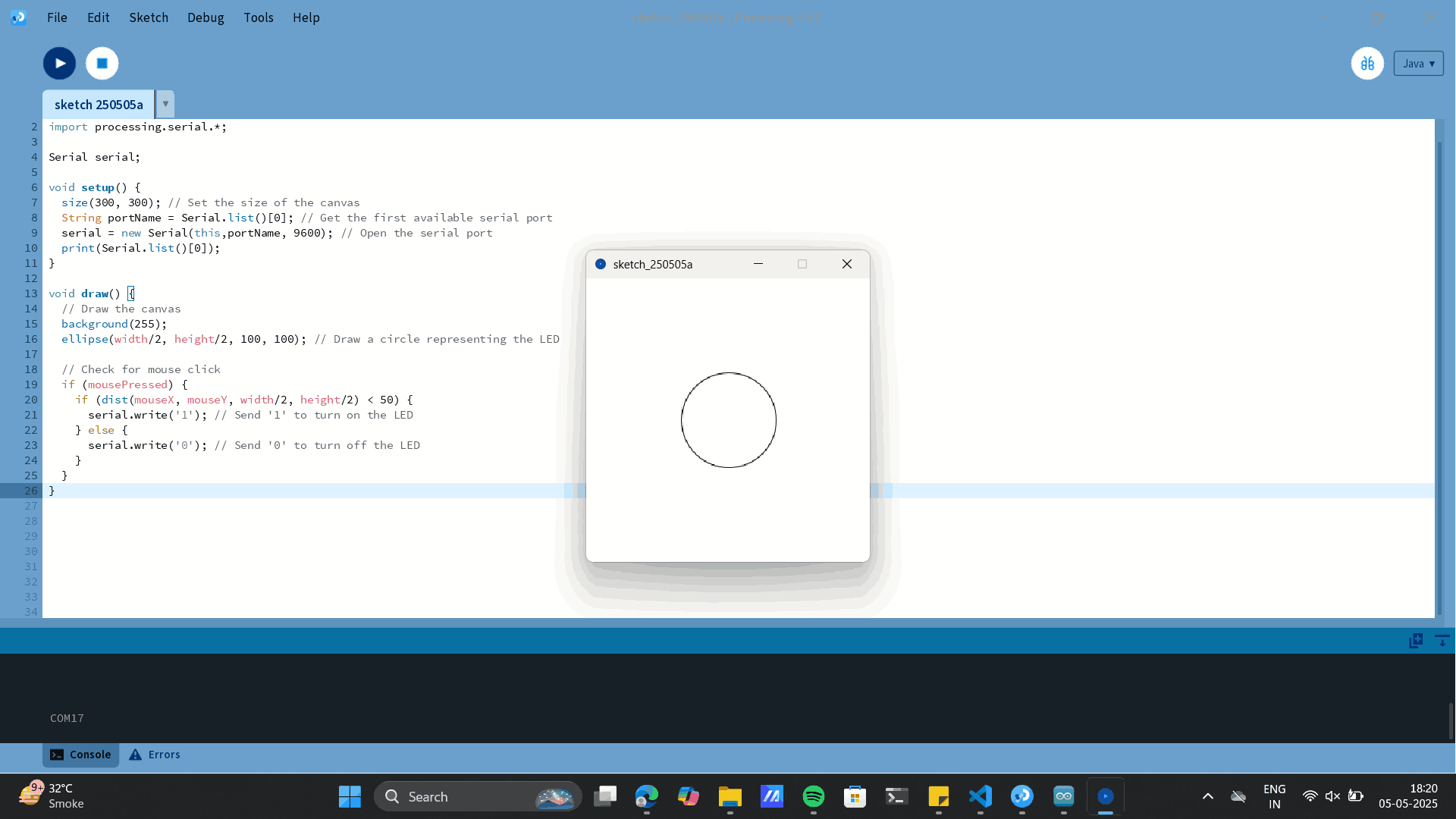
Processing interface with circle
Mouse to inbuild Xaio LED blink
RGB spectrum
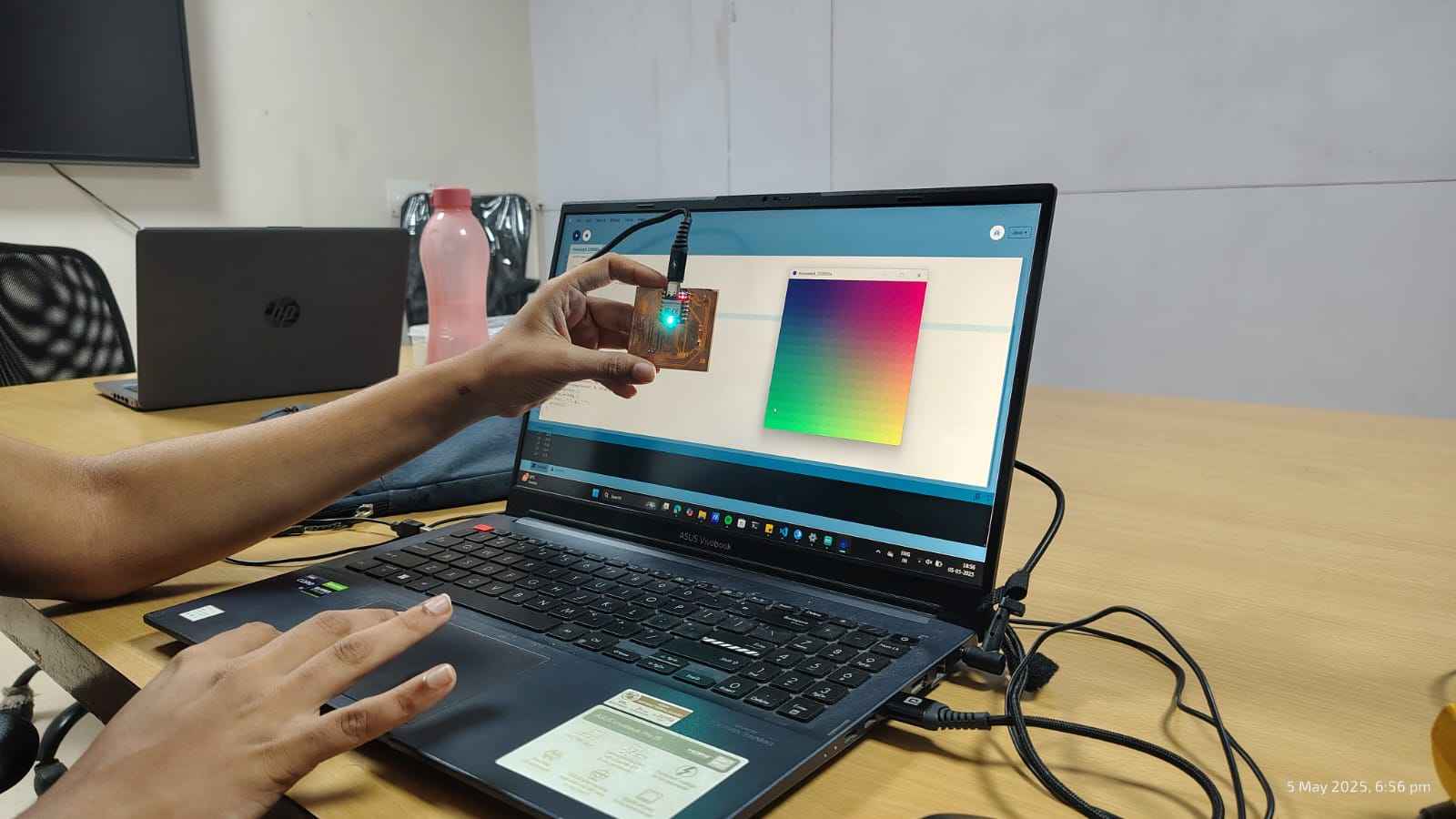
Next, I experimented with the RGB spectrum. The idea was that the Processing code would generate a color spectrum, and depending on where I clicked, it would send the corresponding RGB values to the RP2040, causing the inbuilt RGB LED to light up in that color.
Like the previous steps I upload the below codes to Processing and Arduino respectively.
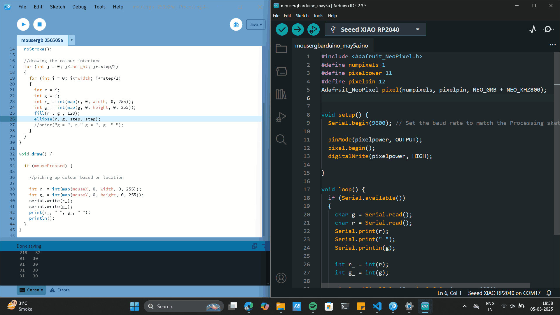 Processing Code:
                    import processing.serial.*;

                    Serial serial;

                    void setup() {

                      size(400, 400); // Set the size of the canvas
                      String portName = Serial.list()[0]; // Get the first available serial port
                      serial = new Serial(this, portName, 9600); // Open the serial port
                      print(Serial.list()[0]);

                      int step = 50;
                      noStroke();

                      //drawing the colour interface
                      for (int j = 0; j<=height; j+=step/2)
                      {
                        for (int i = 0; i<=width; i+=step/2)
                        {
                          int r = i;
                          int g = j;
                          int r_ = int(map(r, 0, width, 0, 255));
                          int g_ = int(map(g, 0, height, 0, 255));
                          fill(r_, g_, 128);
                          ellipse(r, g, step, step);
                          //print("g = ", r," g = ", g, " ");
                        }
                      }
                    }

                    void draw() {

                      if (mousePressed) {

                        //picking up colour based on location

                        int r_ = int(map(mouseX, 0, width, 0, 255));
                        int g_ = int(map(mouseY, 0, height, 0, 255));
                        serial.write(r_);
                        serial.write(g_);
                        print(r_, " ", g_, " ");
                        println();
                      }
                    }
                    #include
                        #define numpixels 1
                        #define pixelpower 11
                        #define pixelpin 12
                        Adafruit_NeoPixel pixel(numpixels, pixelpin, NEO_GRB + NEO_KHZ800);


                        void setup() {
                          Serial.begin(9600); // Set the baud rate to match the Processing sketch

                          pinMode(pixelpower, OUTPUT);
                          pixel.begin();
                          digitalWrite(pixelpower, HIGH);

                        }

                        void loop() {
                          if (Serial.available())
                          {
                            char g = Serial.read();
                            char r = Serial.read();
                            Serial.print(r);
                            Serial.print(" ");
                            Serial.println(g);

                            int r_ = int(r);
                            int g_ = int(g);

                            pixel.setPixelColor(0, pixel.Color(r_, g_, 128));
                            pixel.show();
                            delay(200);
                            pixel.setPixelColor(0, pixel.Color(0, 0, 0));
                            pixel.show();
                          }
                        }
RGB 1
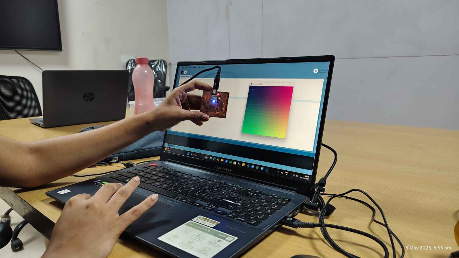
RGB 2
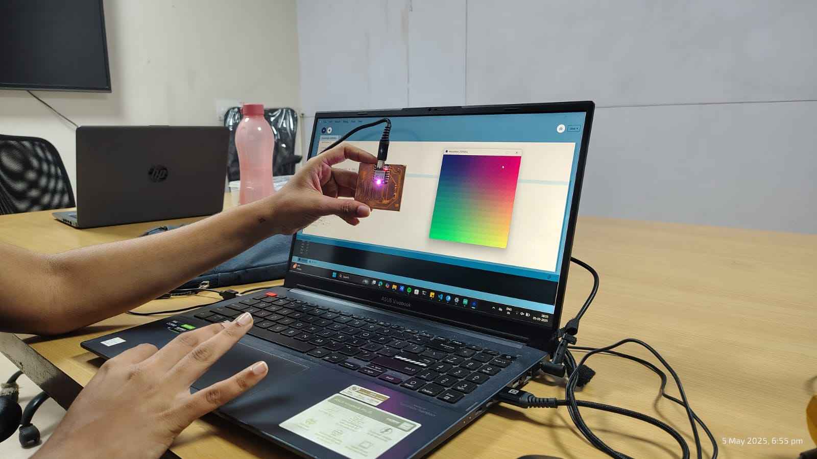
RGB 3
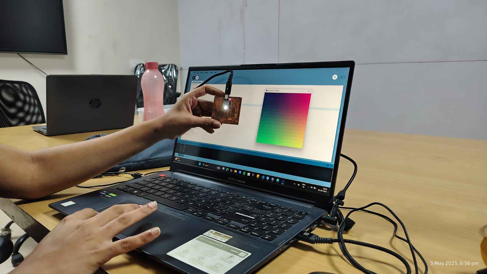
RGB 4
Blynk.io
Blynk is an Internet of Things (IoT) platform that enables you to control and monitor hardware devices remotely. It provides both mobile and web applications for seamless interaction with connected hardware. Blynk is relatively easy to grasp, and its drag-and-drop graphical interface makes it very user-friendly.
You can download the website from: Blynk.io. Chinmay Sir guided us in the process.
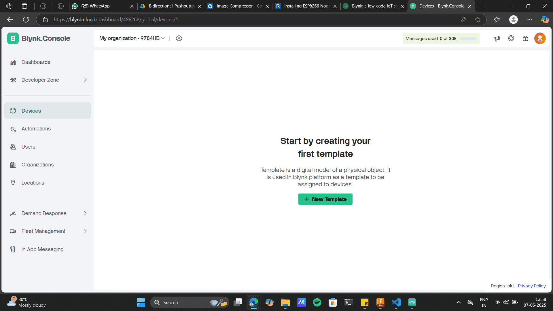
Login to the software, The interface and Click on NEW TEMPLATE
I was using ESP8266: Node MCU, add the project name below.
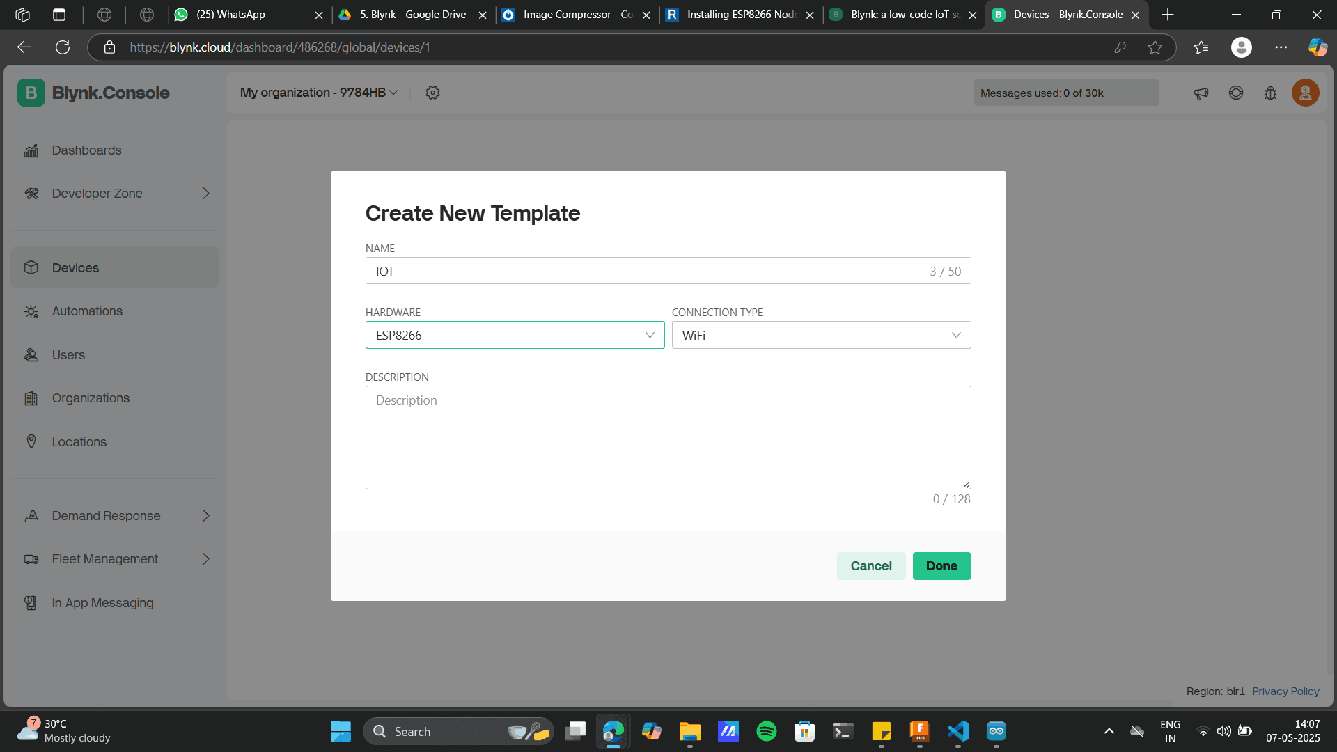
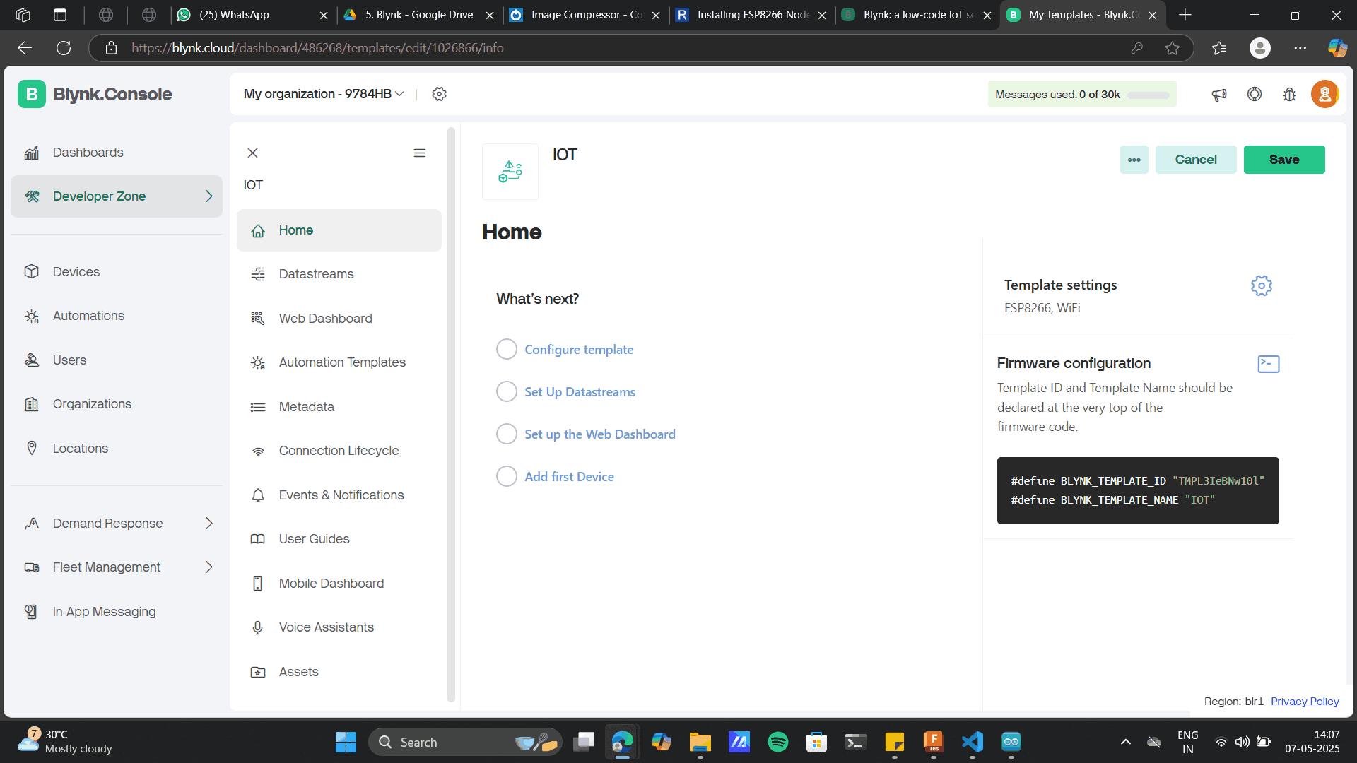
Creating the project will give you an unique Template ID, choose setup data stream
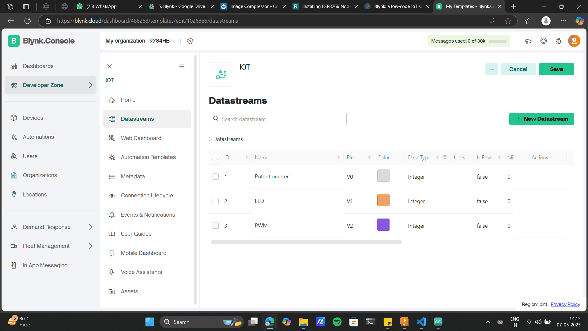
Datastream> New Datastream> Virtual pin
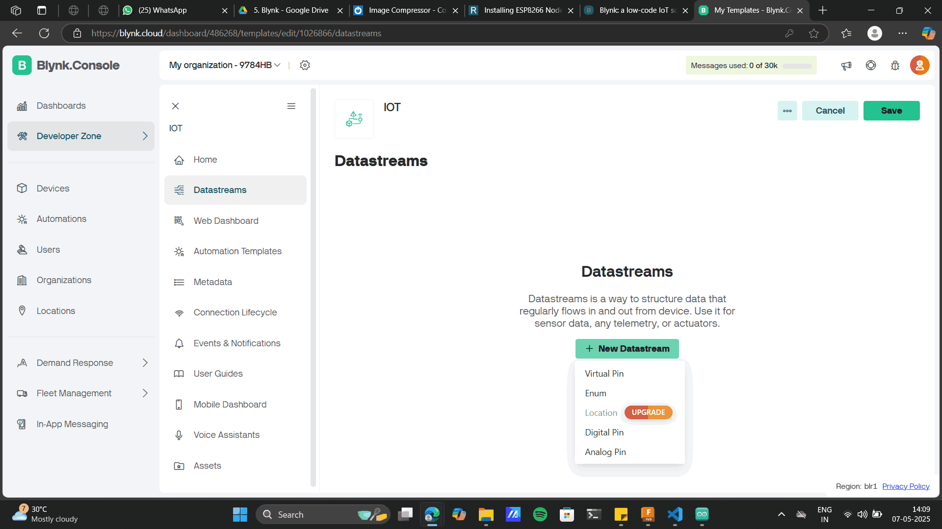
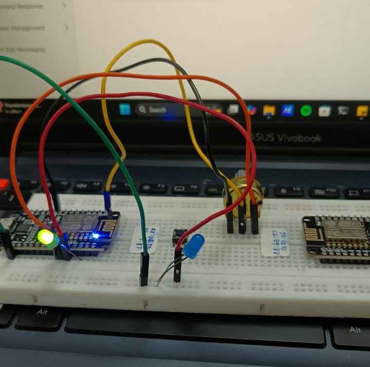
In the virtual data stream, add different components that you will use from this app interface to the hardare side. I planned to use a a switch to ON/OF an LED and control the LED brightness on PWM using a potentiometer. Thus in ther Virtual data stream, I created three virtual pins as LED, potentiometer and PWM.
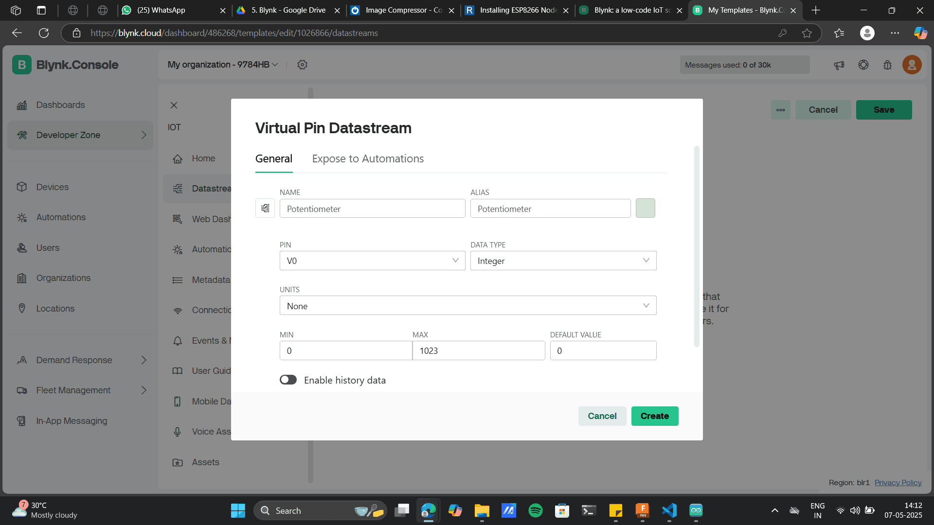
Potentiometer with max Pin value as 1023.
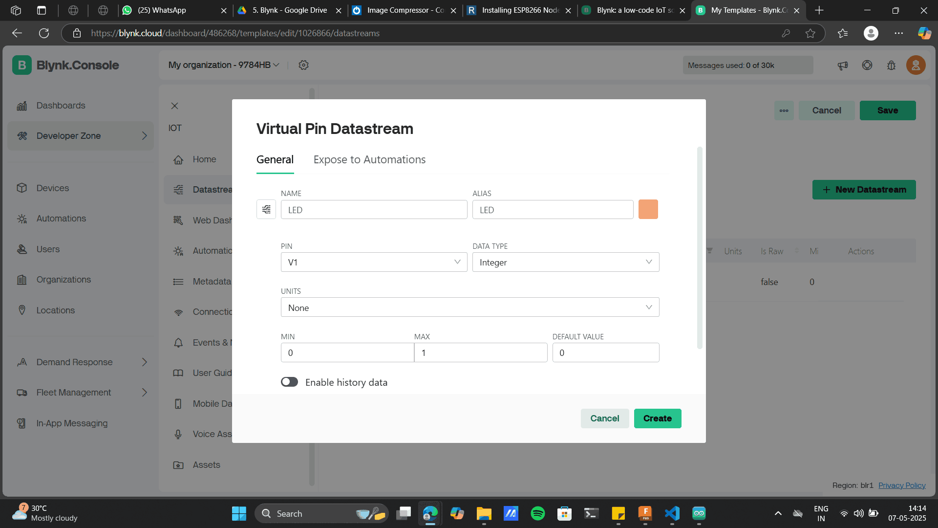
LED Virtual Pin
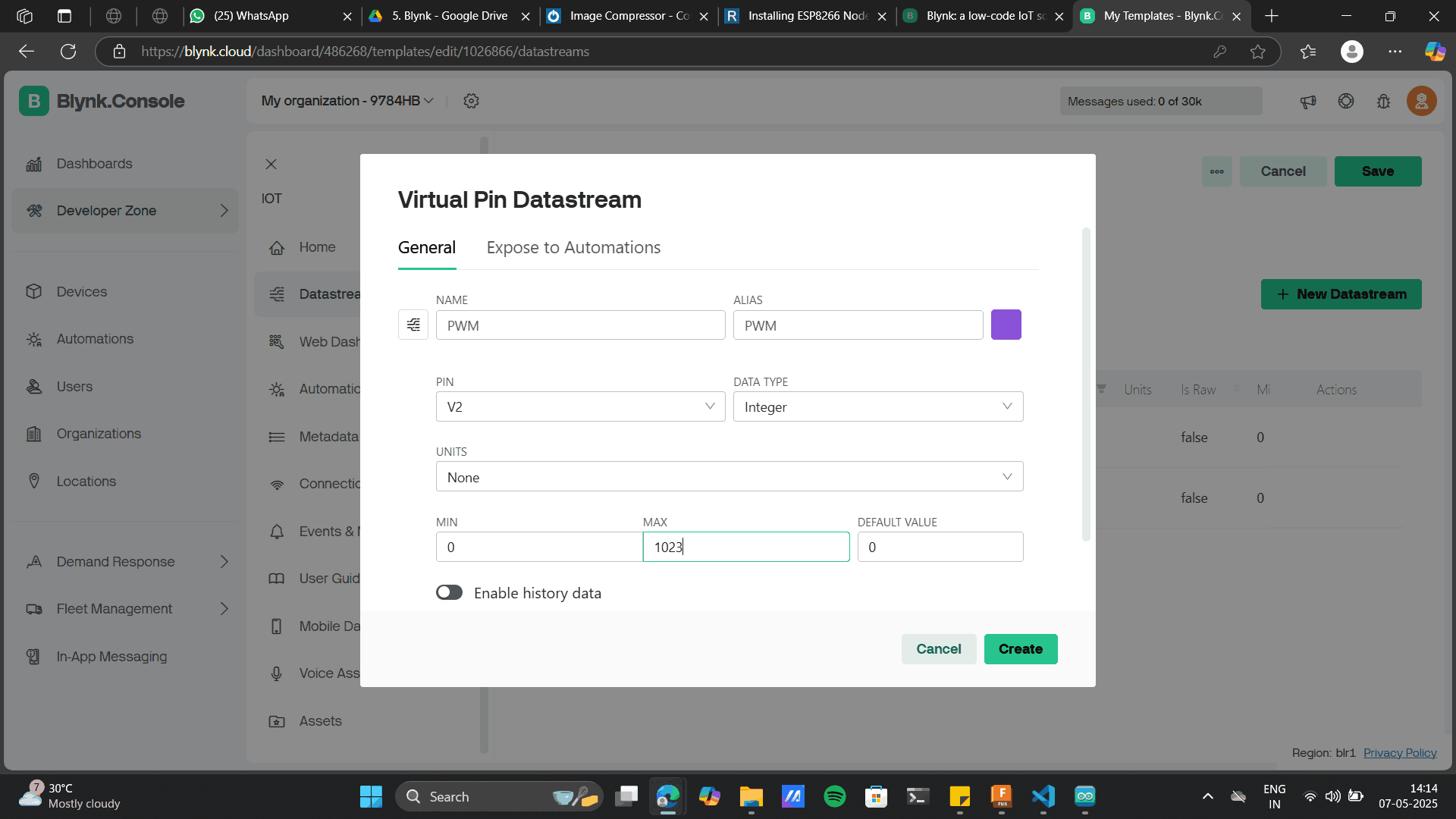
PWM with max Pin value as 1023.
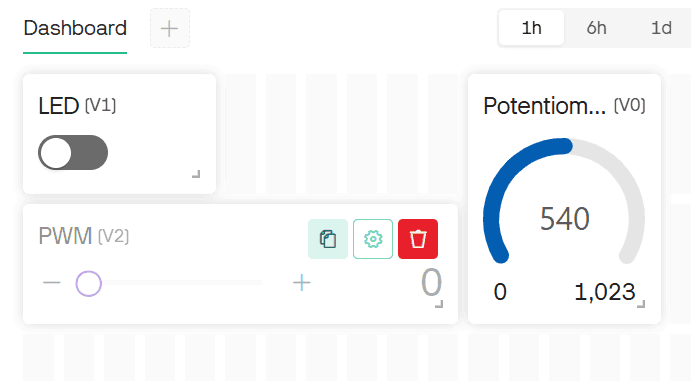
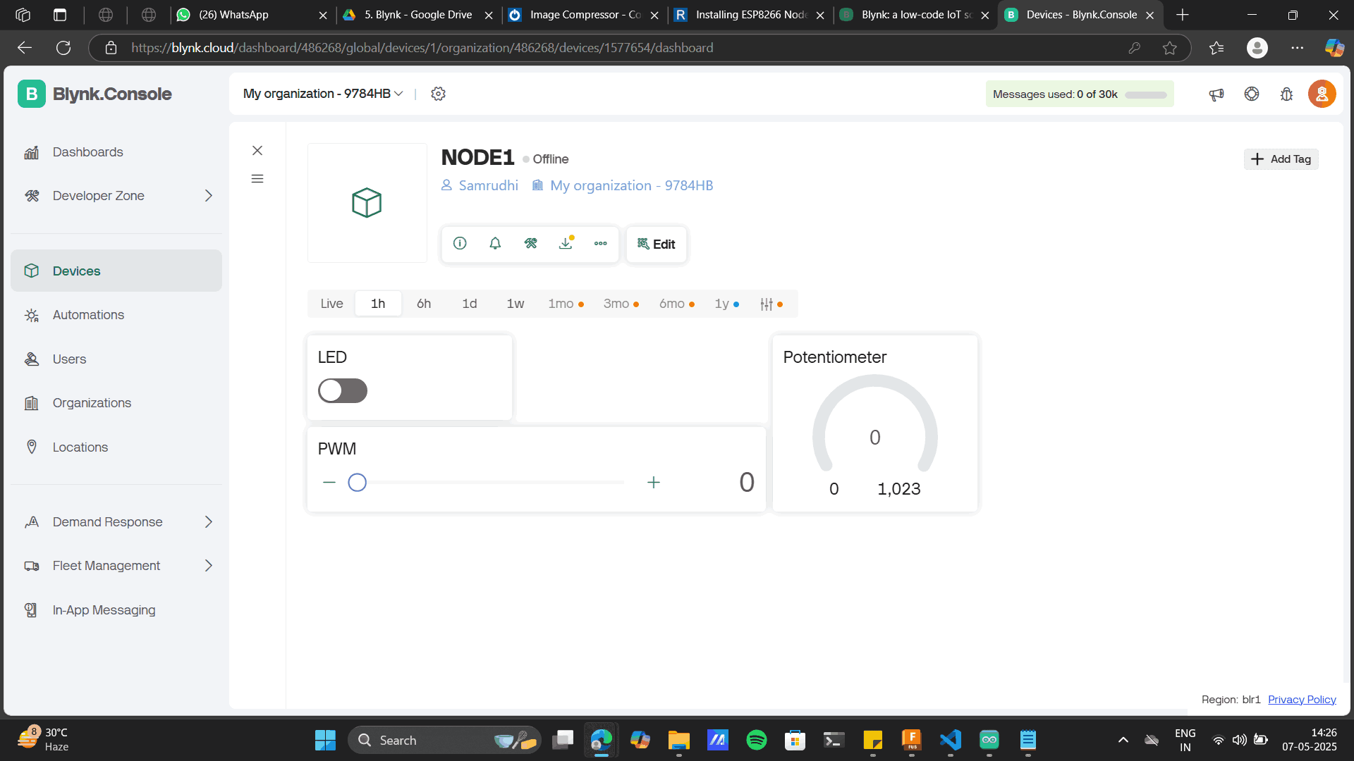
After creating each of them, the dashboard will the each data stream u created.
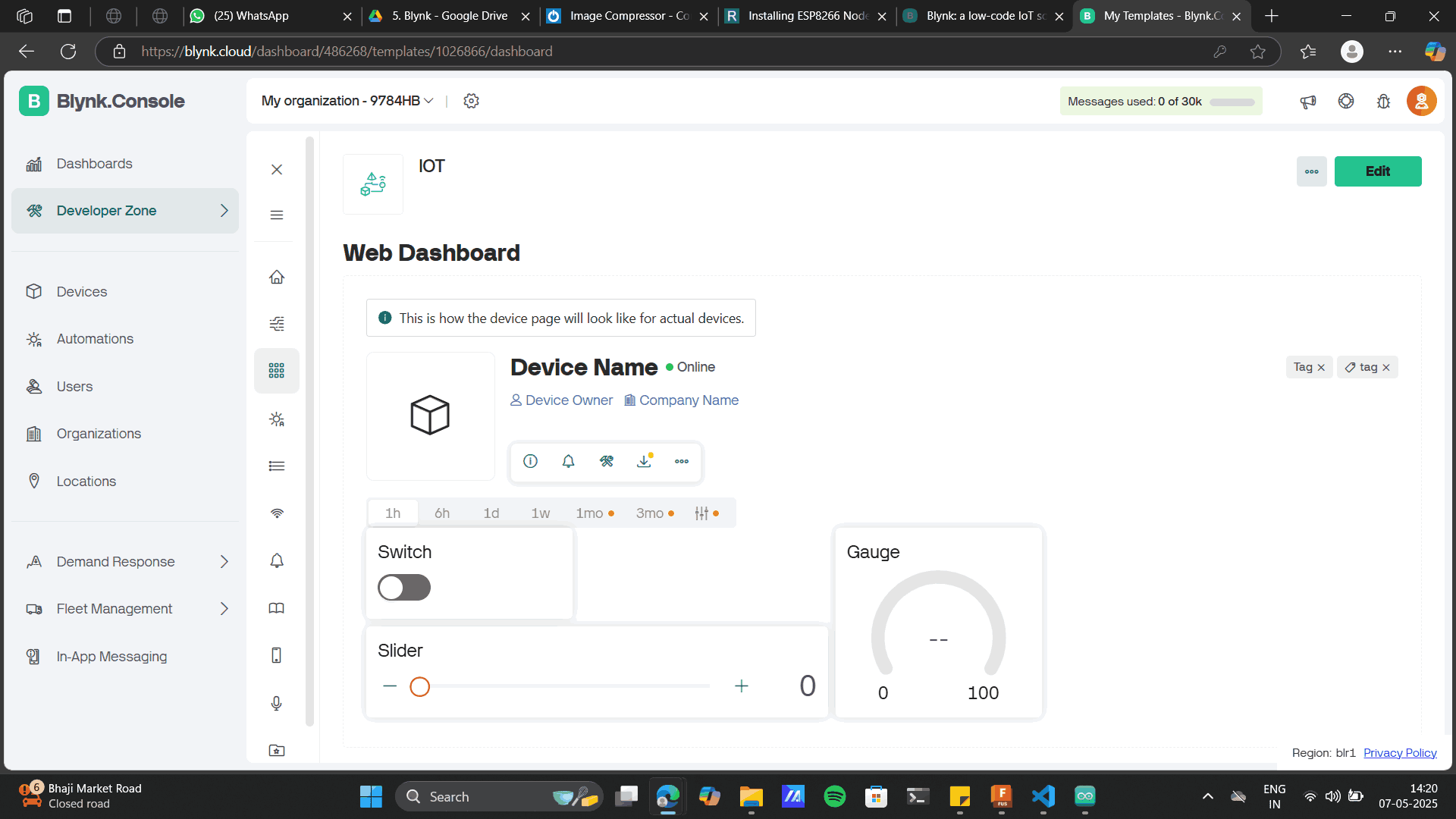
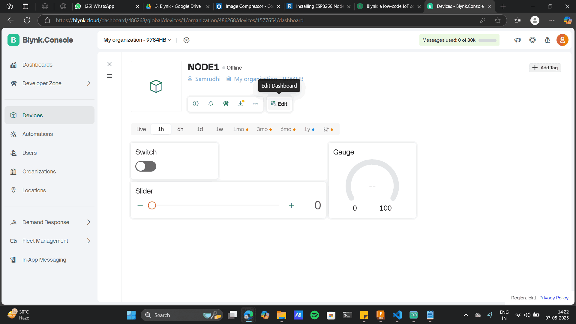
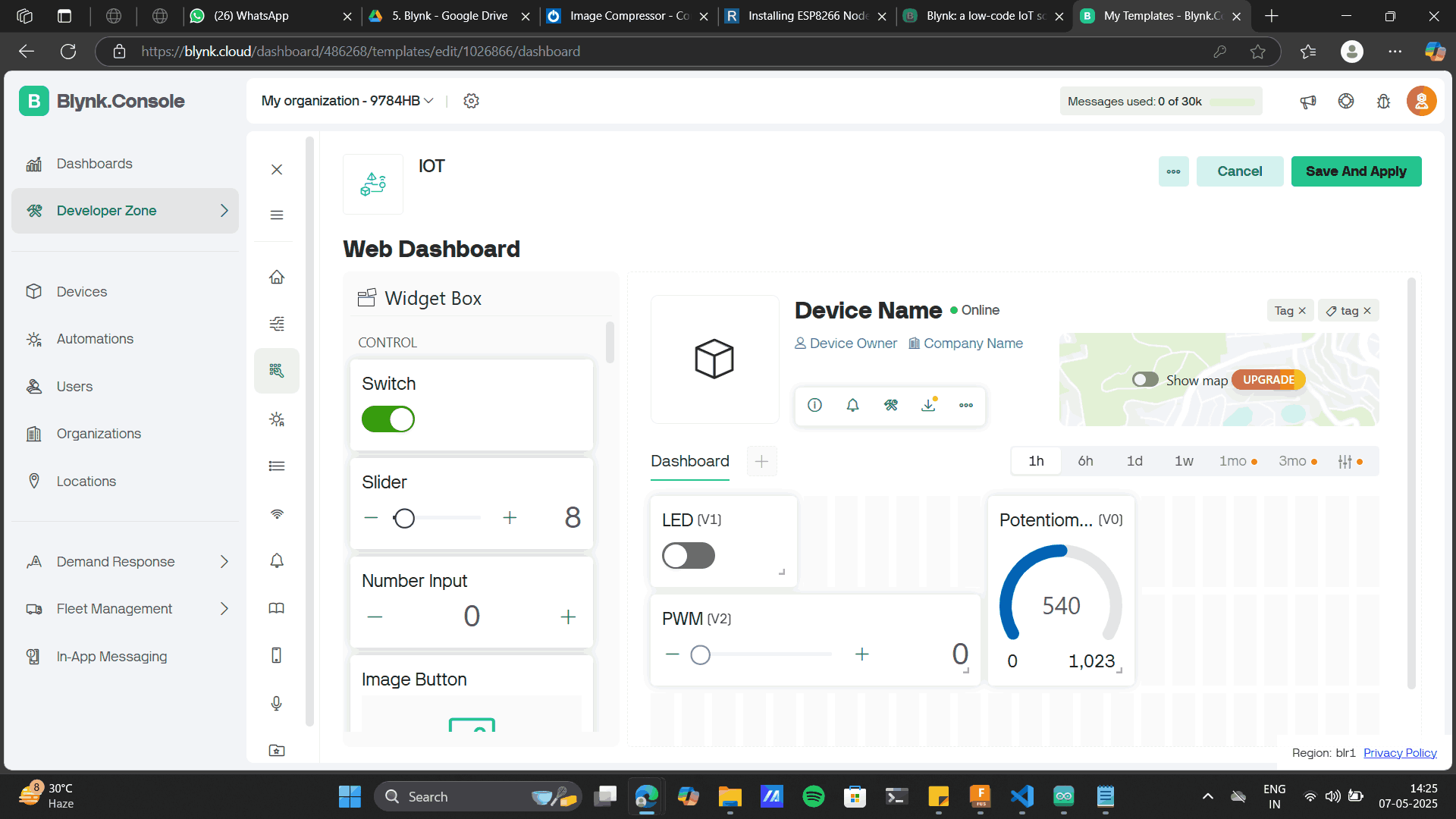
Now click on the web dashboard to find the below screen with various widgets.
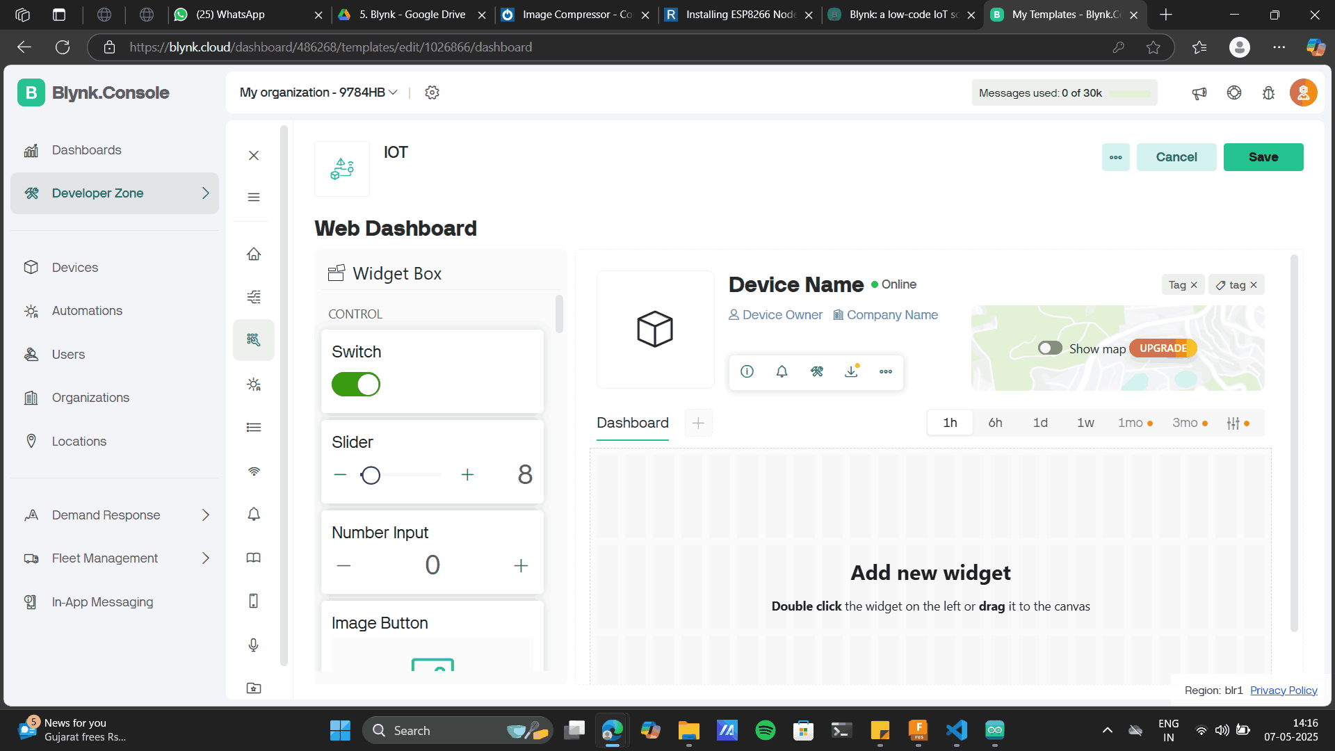
To the dashboard, drag and drop the below widgets.
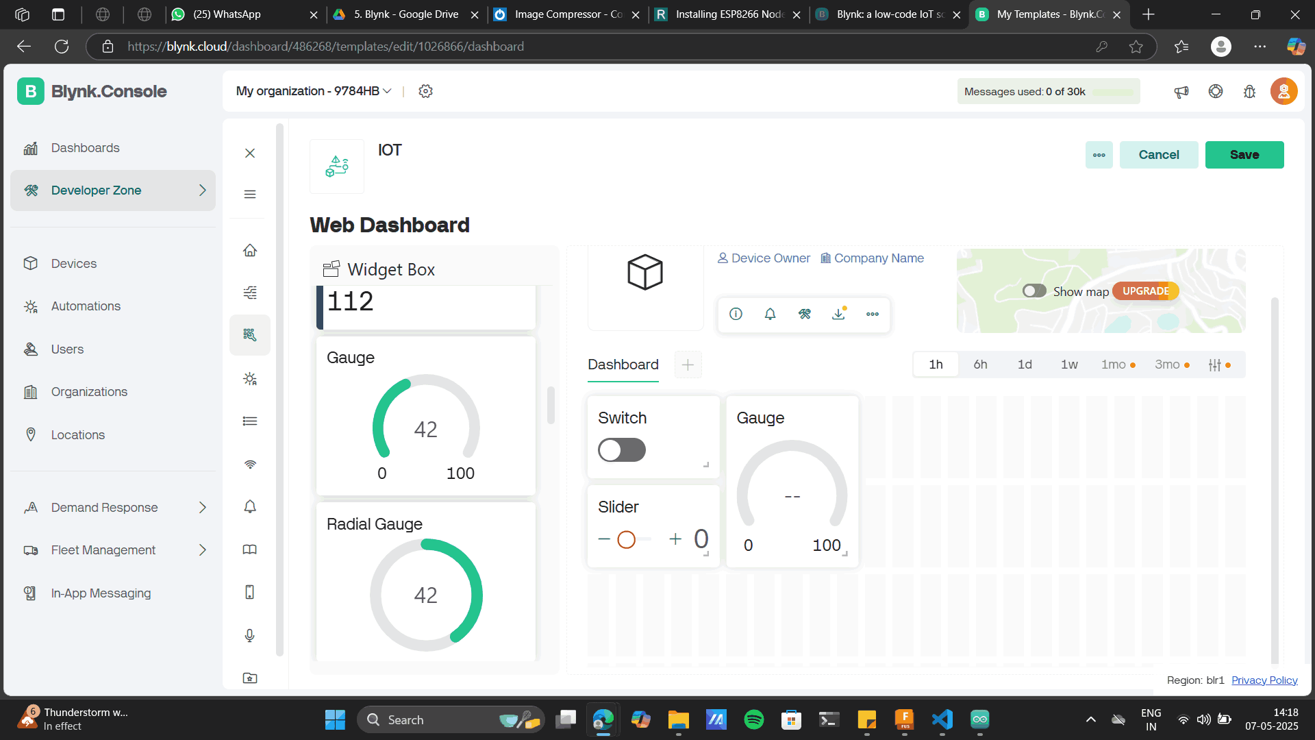
Slider for POT, Switch for push buttonand Gauge for PWM.
Saving this will give you the web dashboard.
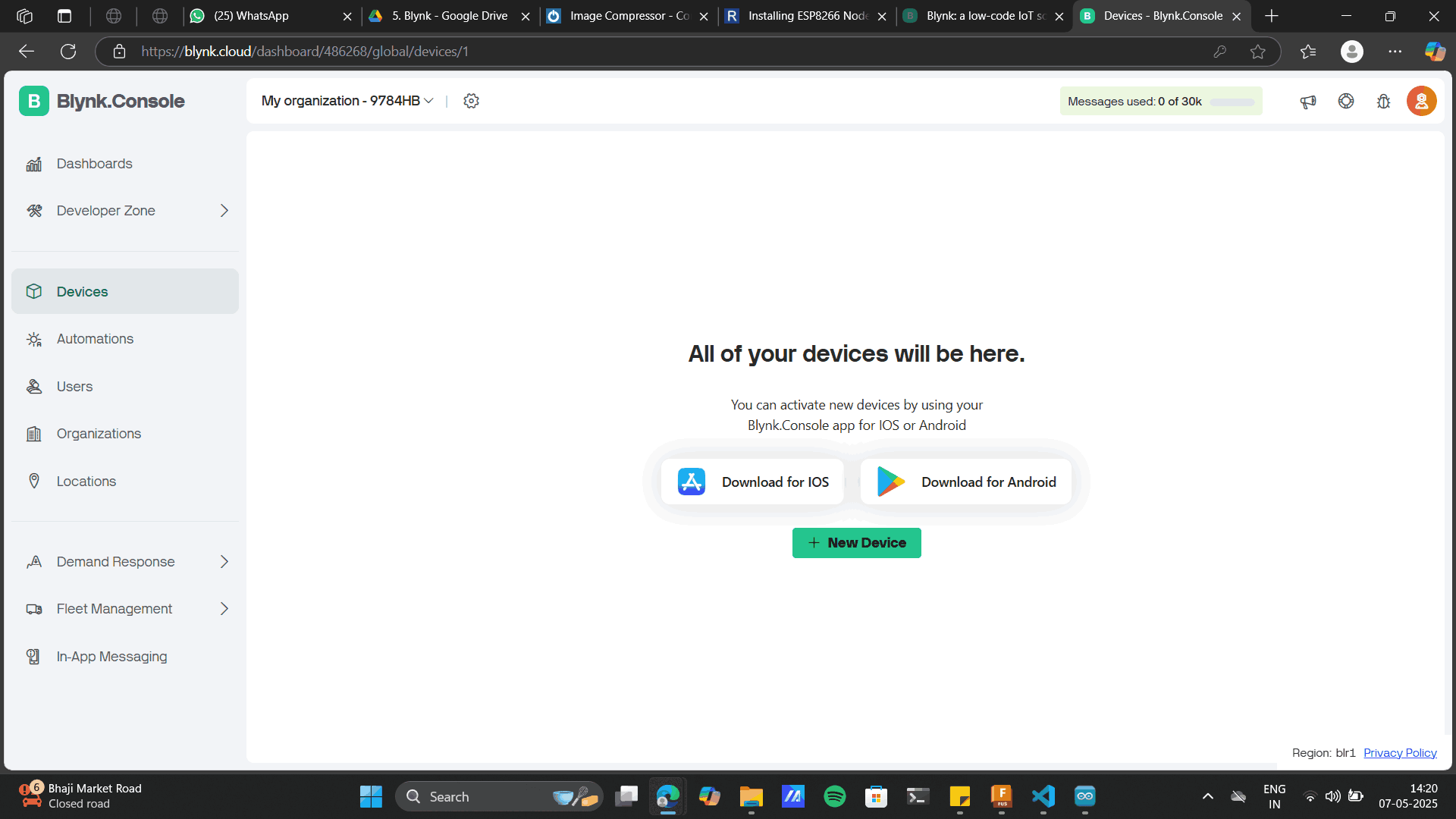
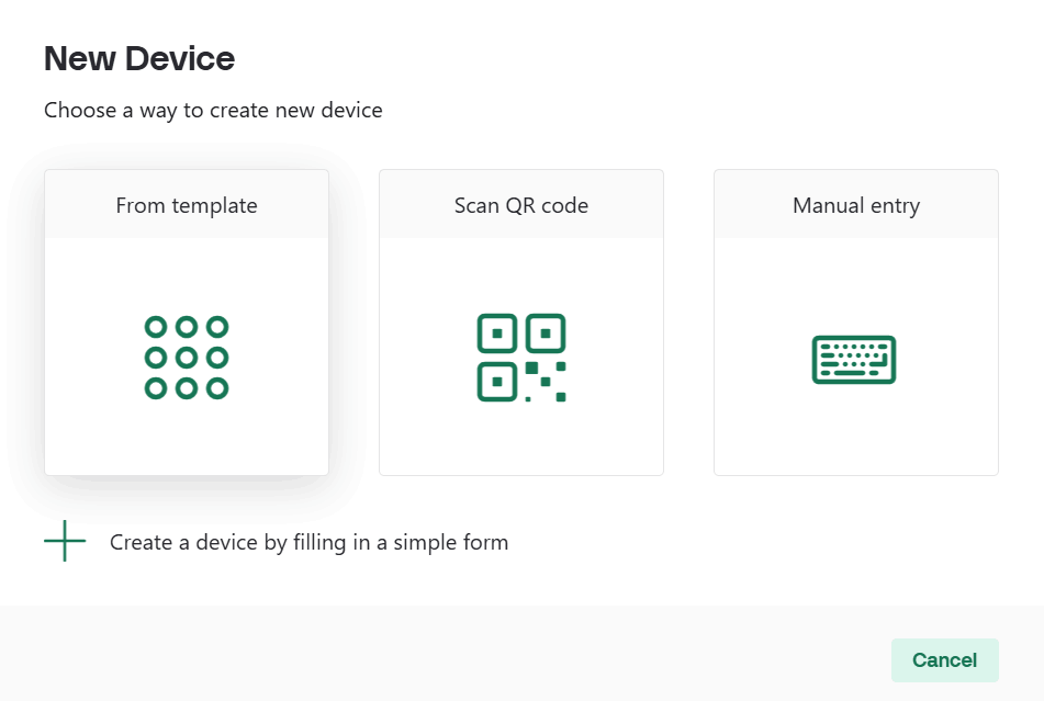
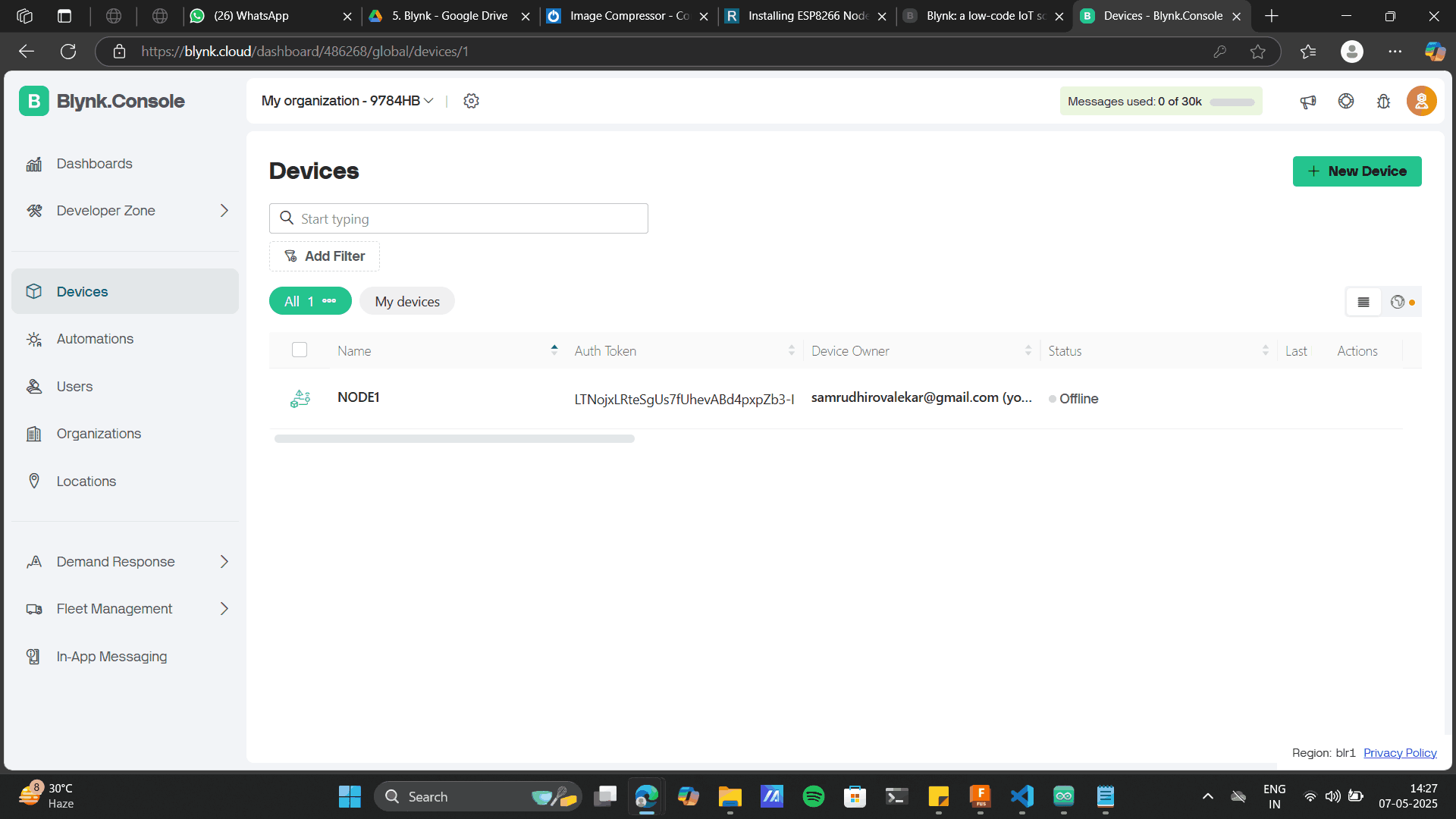
Go to Devices and create a NEW DEVICE
NEW DEVICE> FROM TEMPLATE
Add the template name which u set before and add the device name.
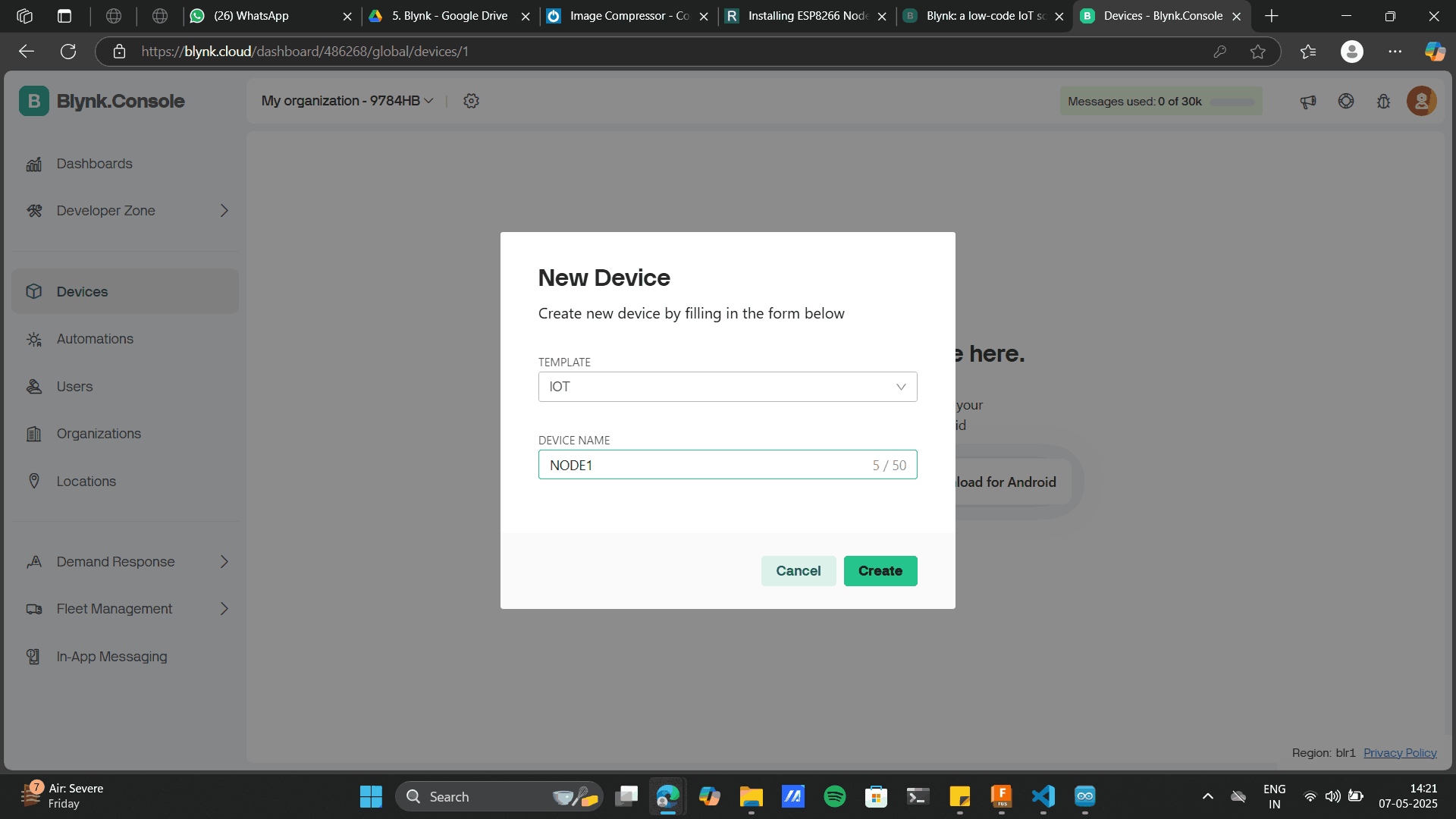
New device is create
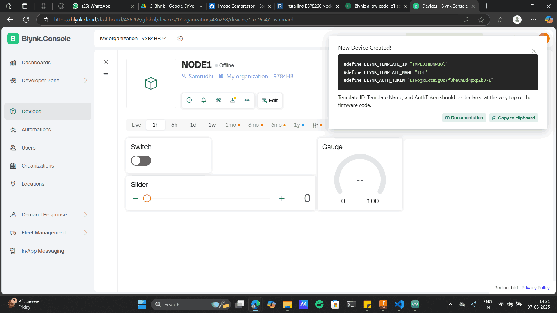
This gives you a code including an unique:
Template ID
Template Name (as u set before)
Authorization code (Most imp)
Copy the above code and add to note.
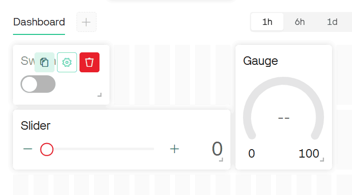
Edit each of the widget to add specifications.
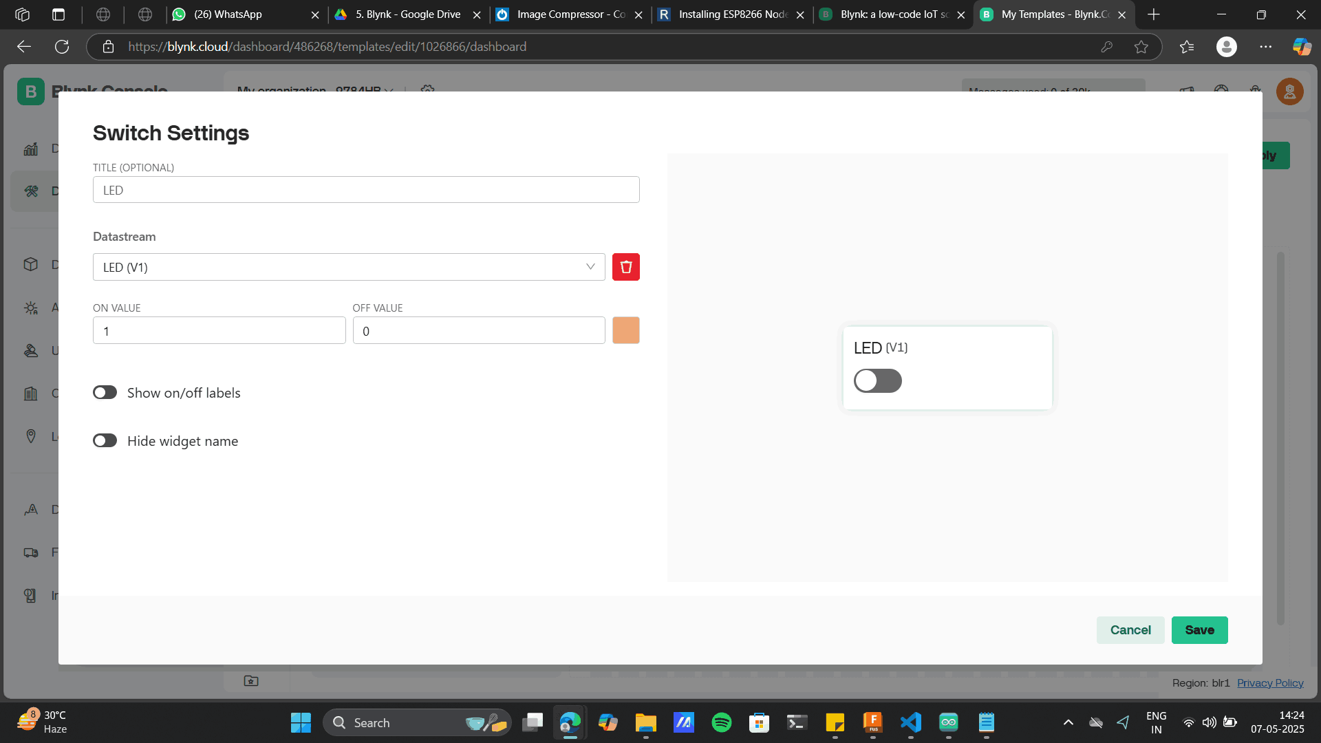
Add switch settings to the datastream: LED
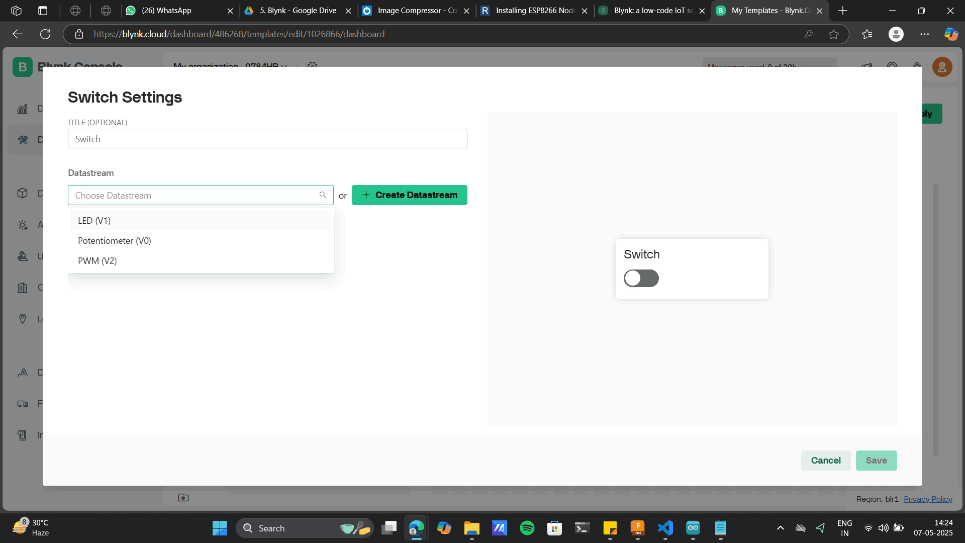
Add other details and Save
Add PWM widget settings to the datastream: PWM
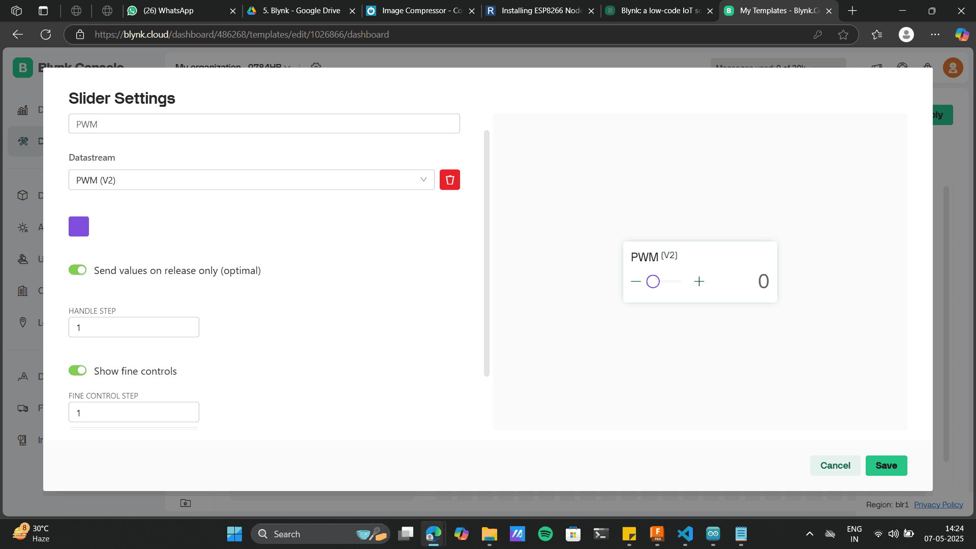
Add Potentiometer widget settings to the datastream: Potentiometer.
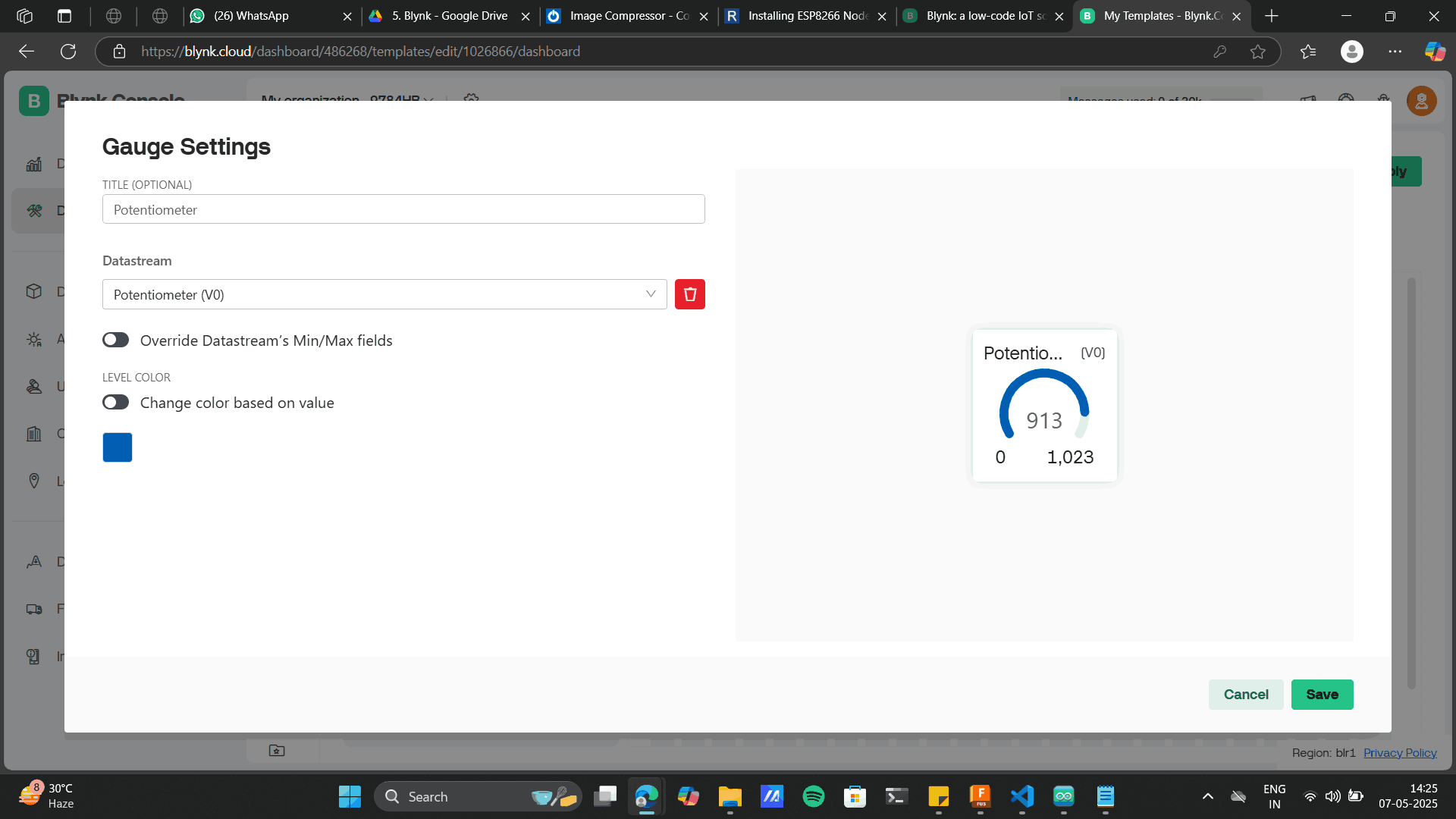
Save each widget> Save and apply
//--------------------------------------------------------------------------------------------------------------------------
//Datastreams on Blynk -
// V0 - Potentiometer
// V1 - LED Switch
// V2 - PWM LED
//--------------------------------------------------------------------------------------------------------------------------
#define BLYNK_TEMPLATE_ID "TMPL3IeBNw10l"
#define BLYNK_TEMPLATE_NAME "IOT"
#define BLYNK_AUTH_TOKEN "LTNojxLRteSgUs7fUhevABd4pxpZb3-I"
//--------------------------------------------------------------------------------------------------------------------------
// Comment this out to disable prints and save space
#define BLYNK_PRINT Serial
//--------------------------------------------------------------------------------------------------------------------------
// Initialize required libraries
#include
#include
//--------------------------------------------------------------------------------------------------------------------------
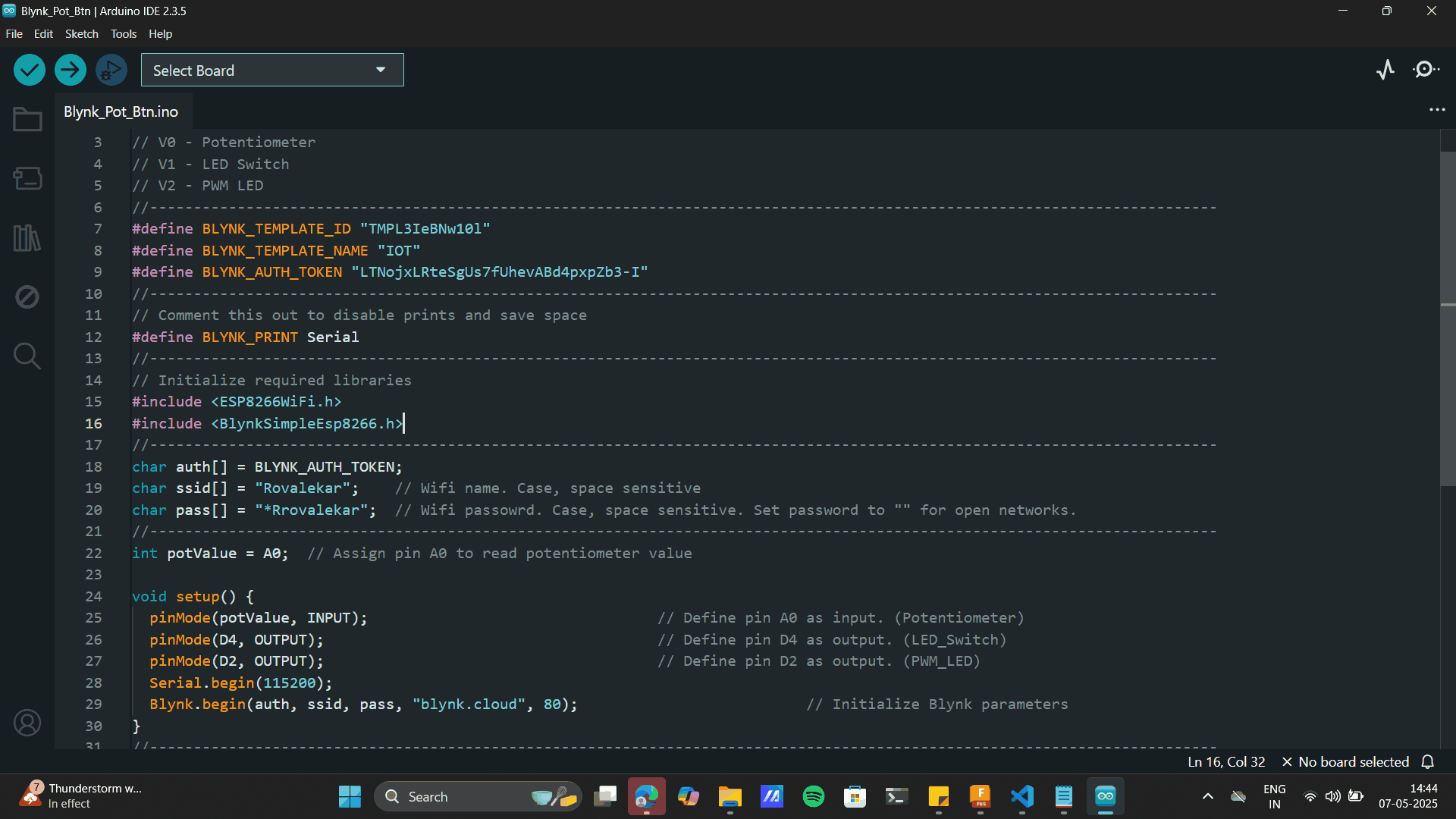
char auth[] = BLYNK_AUTH_TOKEN;
char ssid[] = "HONOR_X9b_5G"; // Wifi name. Case, space sensitive
char pass[] = "shrey231004"; // Wifi passowrd. Case, space sensitive. Set password to "" for open networks.
//--------------------------------------------------------------------------------------------------------------------------
int potValue = A0; // Assign pin A0 to read potentiometer value
void setup() {
pinMode(potValue, INPUT); // Define pin A0 as input. (Potentiometer)
pinMode(D4, OUTPUT); // Define pin D4 as output. (LED_Switch)
pinMode(D2, OUTPUT); // Define pin D2 as output. (PWM_LED)
Serial.begin(115200);
Blynk.begin(auth, ssid, pass, "blynk.cloud", 80); // Initialize Blynk parameters
}
//--------------------------------------------------------------------------------------------------------------------------
// Virtual Pin V1. This function takes value from pin V0 from Blynk and updates it on ESP board.
BLYNK_WRITE(V1) {
int pinValue = param.asInt(); // Assigning incoming value from pin V1 to a variable
if (pinValue == 1) { //
digitalWrite(D4, HIGH);
}
else {
digitalWrite(D4, LOW);
}
}
//--------------------------------------------------------------------------------------------------------------------------
// Virtual Pin V2. This function takes value from pin V2 from Blynk and updates it on ESP board.
BLYNK_WRITE(V2) {
int PWMValue = param.asInt(); // Assigning incoming value from pin V2 to a variable
analogWrite (D2,PWMValue);
}
//--------------------------------------------------------------------------------------------------------------------------
void loop() {
Blynk.run();
int potValue = analogRead(A0); // Read analog value from potentiometer on pin A0
Blynk.virtualWrite(V0, potValue); // Sends Analog value to Gauge on datastream V0
}
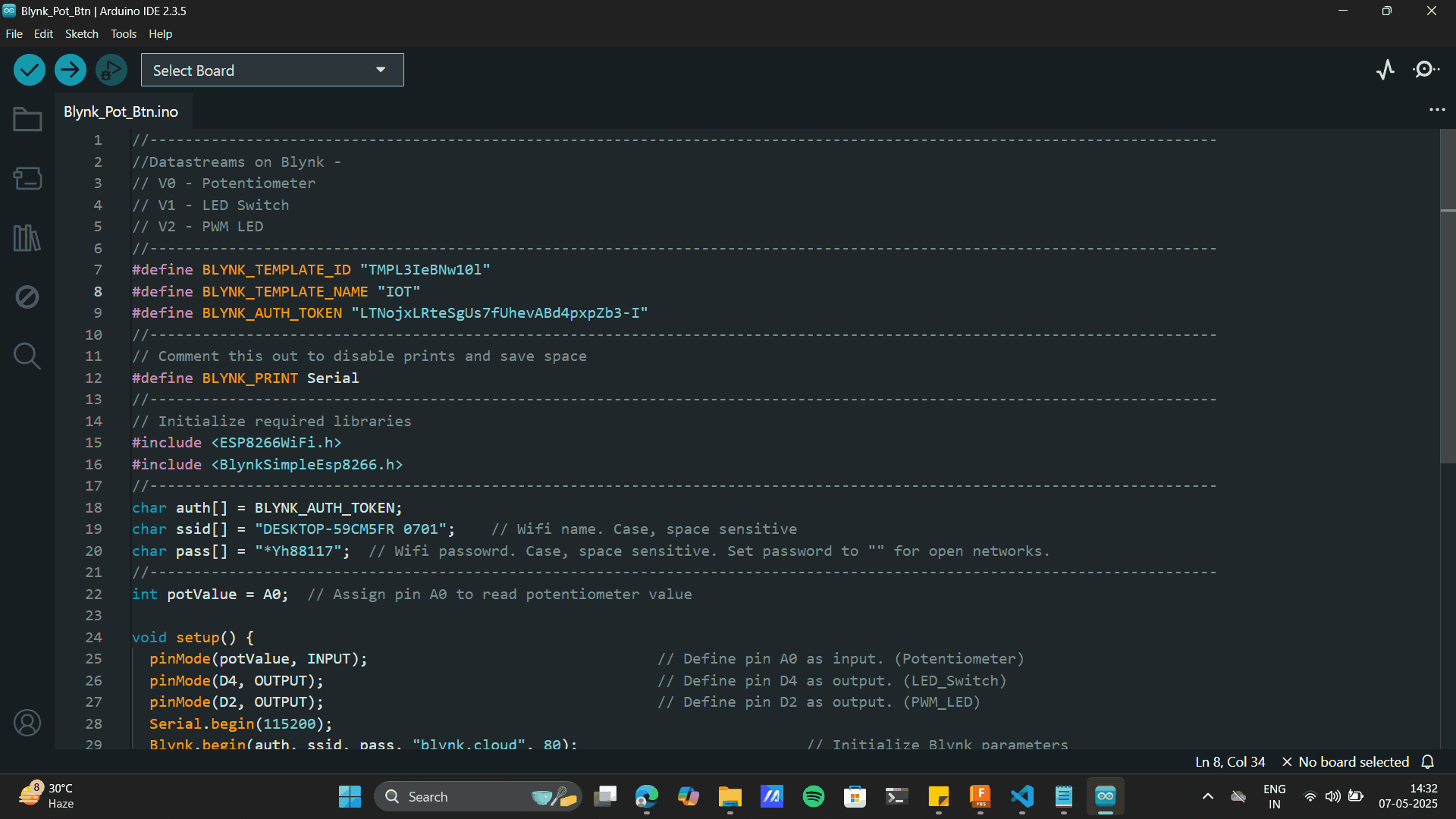
Copy the above code to Arduino Uno
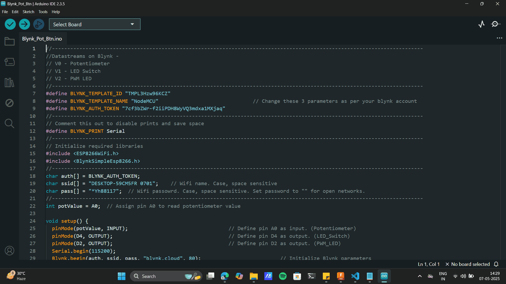
Add the Copied: Template ID, Template name and BLYNK_AUTH_TOKEN.
Library Manager> Blynk> Install
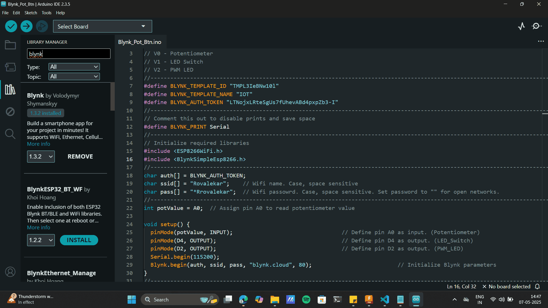
Drop down to the selected lines and add laptop Wifi name and password
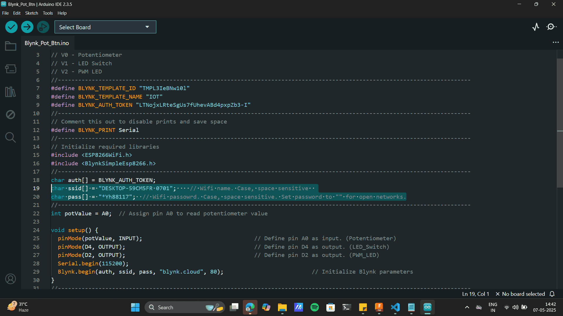
The above didnt work. The status of my Blyk.io was offline. Thus, I connected my Laptop with a stronger WIFI, and switched on a the hotspot and connected it to a hotspot connection. This gave and ONLINE status to my blynk platform as well
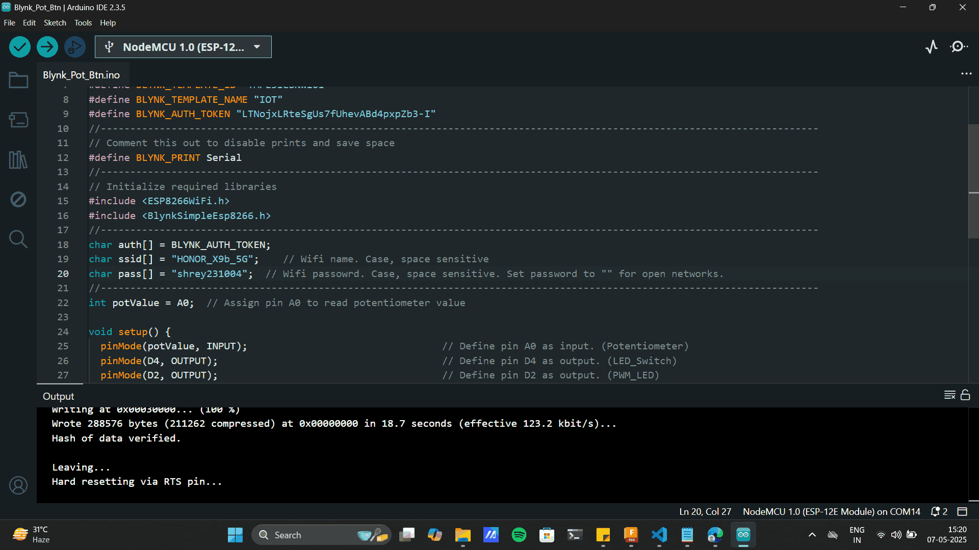
Final Outcome

P5js
I used P5js as a first year student. Coding was very new to me then, its nice to see growth as I feel quite fimiliar with the alien coding language now. p5.js is a JavaScript library designed to make creative coding easy and accessible, especially for artists, designers, educators, and beginners.
P5js Interface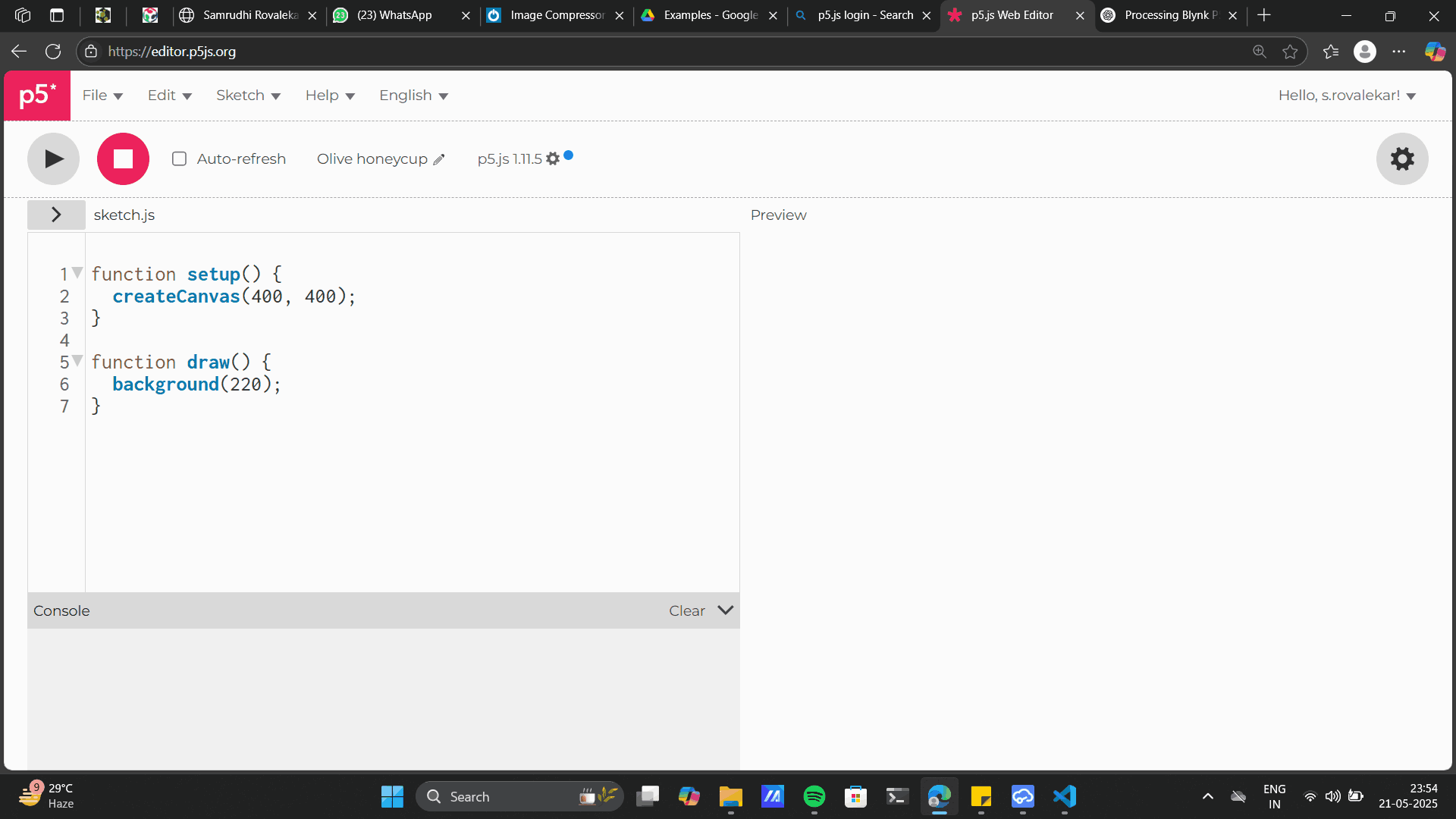
Thanks to the open software that it is, I could source my very first written code: It was a mickey mouse trailing shapes that follow the two circle and a rectangle. With the semi-transparent fill (alpha = 10) with smoky or trailing visual effect, and overlapping shapes. Whenever you left click your mouse the mickey gives a fill opacity effect otherwise it gives a trail.
Example1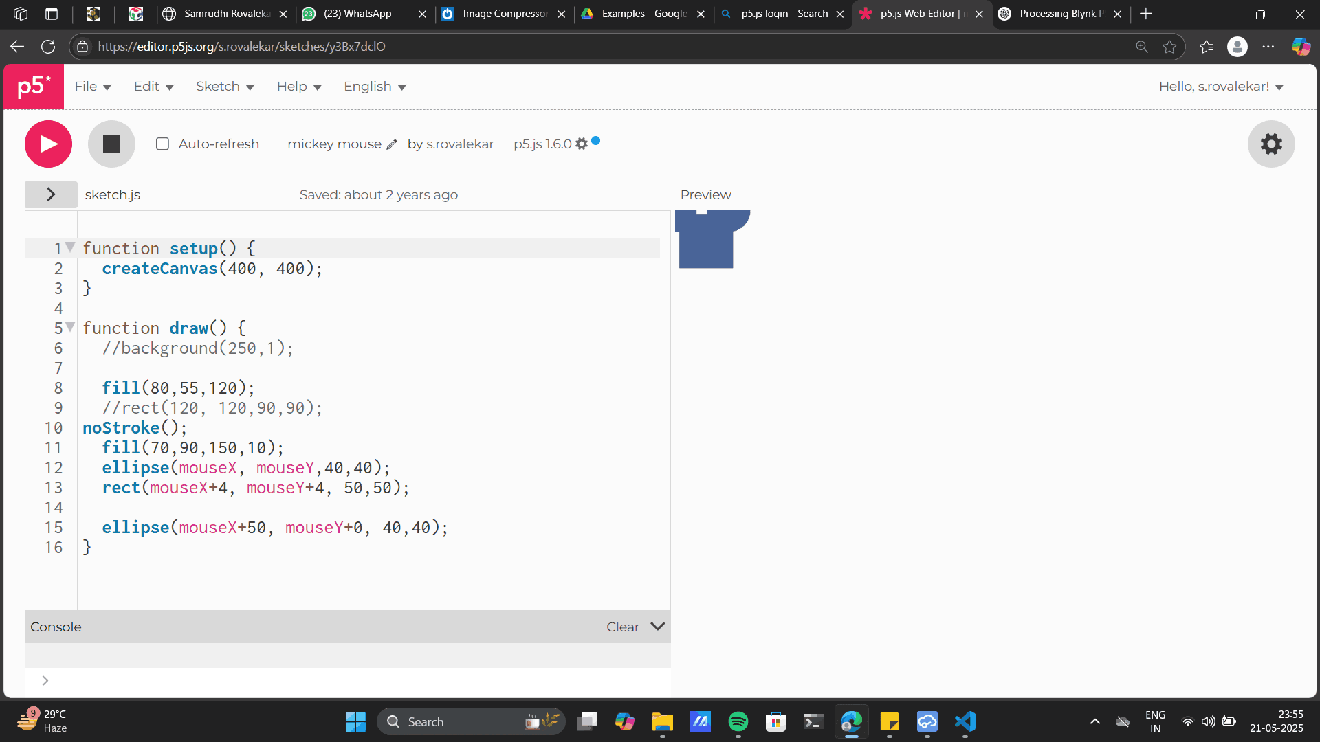
function setup() {
        createCanvas(400, 400);
      }

      function draw() {
        //background(250,1);

        fill(80,55,120);
        //rect(120, 120,90,90);
      noStroke();
        fill(70,90,150,10);
        ellipse(mouseX, mouseY,40,40);
        rect(mouseX+4, mouseY+4, 50,50);

        ellipse(mouseX+50, mouseY+0, 40,40);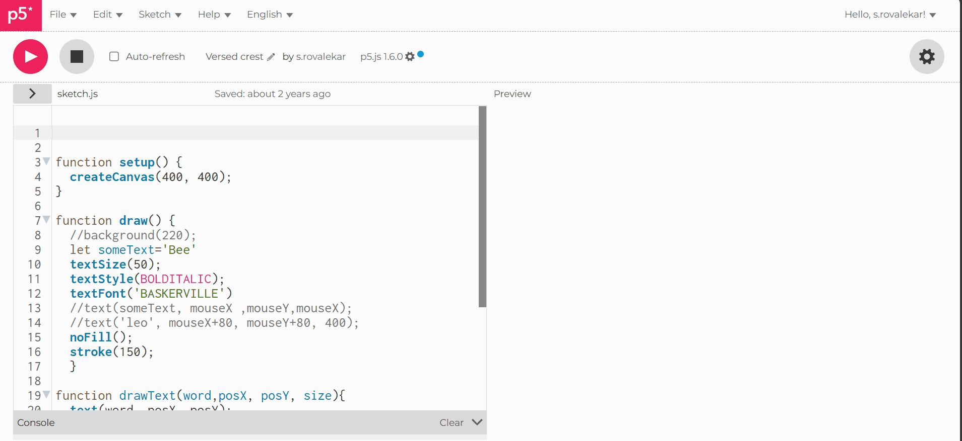
}Example2: This code gives the desired text on mouse click.
      function setup() {
      createCanvas(400, 400);
      }

      function draw() {
      //background(220);
      let someText='Bee'
      textSize(50);
      textStyle(BOLDITALIC);
      textFont('BASKERVILLE')
      //text(someText, mouseX ,mouseY,mouseX);
      //text('leo', mouseX+80, mouseY+80, 400);
      noFill();
      stroke(150);
      }

      function drawText(word,posX, posY, size){
      text(word, posX, posY);
      textSize(size);

      }

      function mouseClicked()
      {
      drawText('Bee', mouseX, mouseY, random(5,50));
      drawText('Leo', mouseX+50, mouseY+50, random(5,50));
      }
Group Assignment
Comparing Processing, P5.js, and Blynk
Processing is a Java-based programming environment widely used for creating visual art and interactive sketches. It excels at producing interactive graphics and also includes libraries for handling sound, video, and other media, making it a versatile tool for creative projects.
P5.js is the JavaScript counterpart to Processing, designed specifically for creative coding on the web. It enables you to build interactive graphics and animations that run directly in web browsers, making it ideal for sharing and showcasing digital art online.
Blynk is an Internet of Things (IoT) platform that allows users to remotely control and monitor hardware devices. It features a mobile and web-based app interface with a drag-and-drop GUI, making it very beginner-friendly. Blynk is especially useful for quick prototyping and real-time interaction with connected devices.
| Tool | Based On | Main Use | Strengths | Platform |
|---|---|---|---|---|
| Processing | Java | Creating visuals and sketches | Great for graphics, sound, and video projects | Desktop (Java IDE) |
| P5.js | JavaScript | Creative coding for the web | Runs in browser, good for animations and interaction | Web (Browser-based) |
| Blynk | IoT Platform | Controlling and monitoring devices | Easy to use, drag-and-drop UI, great for IoT projects | Mobile + Web |
Project files
Mouse to Led Processing codeMouse to Led Aurdino code
Mouse to RGB Processing code
Mouse to RGB Aurdino code Blynk Code