Assignment Brief:
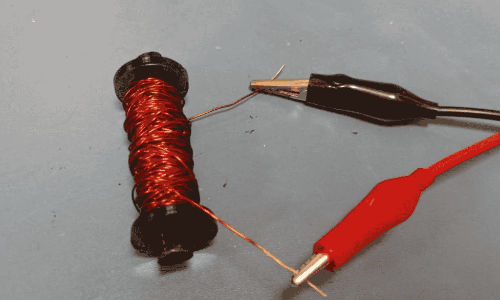
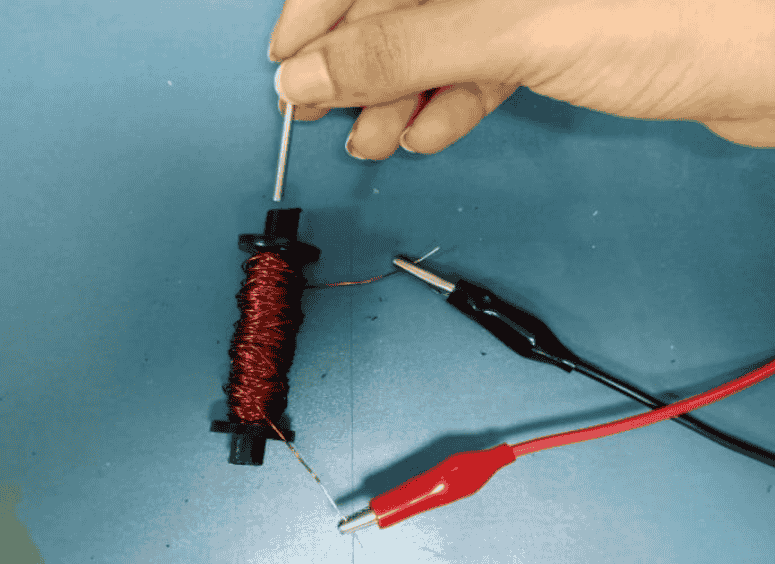
- Group: Measure an output device’s power consumption using a multimeter
- Individual: Add an output device to your microcontroller board.
- Program it to perform a specific function.
Output Devices
Output devices are hardware components that display, project, or produce the results of a computer’s processing. These devices take information from the computer and convert it into a human-perceivable form like visual, audio, or physical output.
Visual Output Devices- LED Matrix Displays: Grid of LEDs used for animations, text, and patterns.
- E-paper Displays: Low-power, paper-like displays used in e-readers.
- Laser Light Shows: High-intensity lasers used for artistic and entertainment purposes.
- Speakers: Convert electrical signals into sound waves for audio output.
- Headphones: Personal audio output devices that provide sound directly to the ears.
- Buzzers: Small devices that produce beeps or alarms for notifications.
- Actuators (Solenoids, Pneumatic Cylinders): Convert electrical energy into mechanical movement.
- Mechanical Switches or Relays: Enable or disable electrical circuits for physical interactions.
- LED Displays: Bright, energy-efficient screens used in signage and indicators.
- LCD Screens: Common in TVs and monitors, use liquid crystals for display.
- OLED Screens: Self-emissive, flexible displays with high contrast and efficiency.
- CRT Monitors: Older bulky monitors using electron beams to display images.
- Motors: Convert electrical energy into rotational motion.
- Servo Motors: Precisely controlled motors used in robotics and automation.
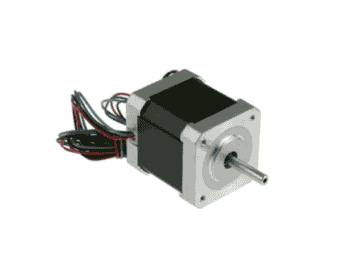
- Stepper Motors: Move in discrete steps, ideal for precision applications.
- Projectors (DLP, LCD, LCoS): Devices that project images onto screens.
- Holographic Displays: Use light diffraction to create three-dimensional visuals.
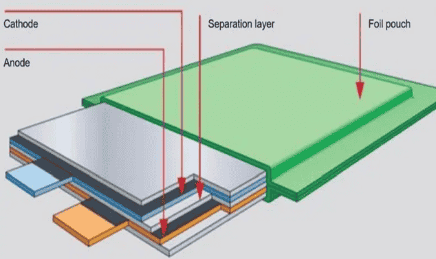
Batteries
Beyond Output devices, I learn about output device controls that is, Batteries. Batteries don’t just supply power—they also regulate and control the behavior of output devices like motors, LEDs, displays, and more. There are mainly two types of batteries: Lithium polymer and lithium Ion. Battery Management System (BMS) BMS is a Key Aspects of Battery Control in Output Devices It prevents overcharging, over-discharging, and overheating and Balances cells in multi-cell batteries (e.g., Li-ion packs in laptops, EVs).
| Feature | LiPo (Lithium Polymer) | Li-ion (Lithium-ion) |
|---|---|---|
| Electrolyte Type | Gel-like | Liquid |
| Weight & Shape | Lightweight, Flexible | Heavier, Rigid |
| Energy Density | Lower | Higher (Longer-lasting) |
| Discharge Rate | Higher (Great for RC, Drones) | Lower (Steady Power Output) |
| Safety | Prone to swelling if overcharged | More stable, less risk of swelling |
| Common Uses | RC Cars, Drones, High-power applications | Phones, Laptops, Electric Vehicles |
Lipo Battery
Lion Battery
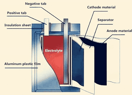
Some other types of Batteries are:
NiMH (Nickel-Metal Hydride): Rechargeable, better than NiCd. Found in cameras and toys.
NiCd (Nickel-Cadmium): Older rechargeable type with memory effect issues. Used in power tools.
Lead-Acid: Heavy, high power output. Used in cars and UPS systems.
Alkaline (AA, AAA, 9V): Non-rechargeable, long shelf life. Used in remotes and clocks.
Zinc-Carbon: Cheap, disposable, low power. Common in basic flashlights and toys.
Solid-State: Future technology, safer, and higher capacity. Emerging in battery innovations.
Sodium-Ion: Eco-friendly, cheaper than Li-ion. Potential future alternative energy storage.
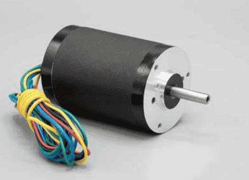
Servo Motor
This week I decided to work with Servo motor as it is a part of my Final Project. I thought that testing the sevo motor speed will be insightful to learn and implement. I started by learning about servos.
A servo motor is a type of motor that provides precise control of angular or linear position, velocity, and acceleration. It consists of a DC or AC motor, a gear system, a position sensor (usually a potentiometer), and a control circuit. Servo has higher ability of Speed position and Power
As I learnt about Servo Motors I was confused between a servo motor, Dc motor and Stepper motor. I asked my professor Pranav Gawde assisted me to understand the difference between Servo and Stepper Motor: Servo has higher ability of Speed position and Power. Stepper Motor has higher torque and precision of controlled steps and a DC motor has a constant high efficient rotatary motion.
DC Motor:
- Type: Continuous rotation motor.
- Control: Speed controlled by voltage, direction by polarity.
- Pros: Simple, high speed, low cost.
- Cons: No precise position control.
- Used In: Fans, toys, pumps, robots.
Servo Motor:
- Type: DC motor with position feedback.
- Control: Controlled by PWM signals (angle-based control).
- Pros: High torque, precise position control.
- Cons: Limited rotation (0-180° in hobby servos).
- Used In: Robotics, RC cars, automation.
Stepper Motor:
- Type: Moves in precise steps.
- Control: Controlled by pulses (steps per revolution).
- Pros: High accuracy, no feedback needed, full rotation control.
- Cons: Needs more power.
- Used In: 3D printers, CNC machines, robotic arms.
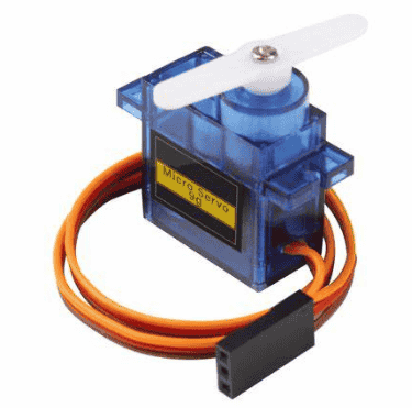
Servo Motor
The internal components of a servo motor and how it functions. Key Parts & Their Roles:
- Drive Gears – Transfer motion from the motor to the output shaft, allowing controlled movement.
- Potentiometer – Provides position feedback to the control circuit, helping maintain accurate angles.
- Integrated Circuit (IC) – The brain of the servo, processing signals and adjusting the motor accordingly.
- Motor – The core driving component that rotates to move the servo arm.
- Servo Case – Protects all internal components and provides structural integrity.
.jpg)
SERVO PIN-OUT
.png)
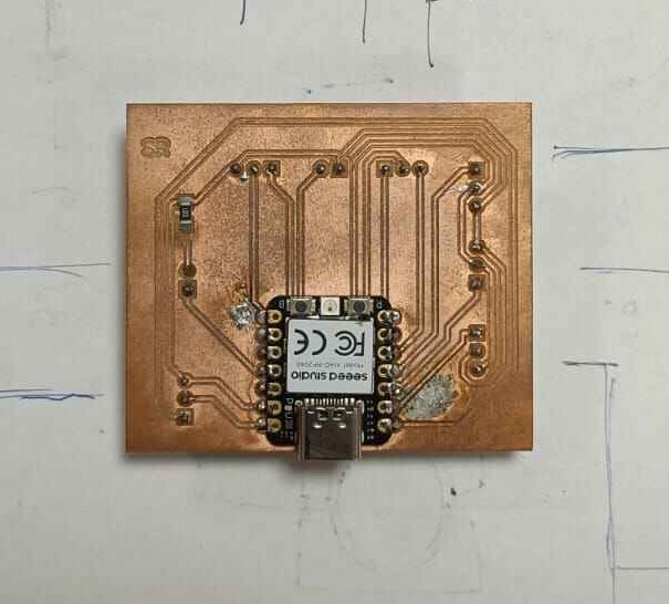
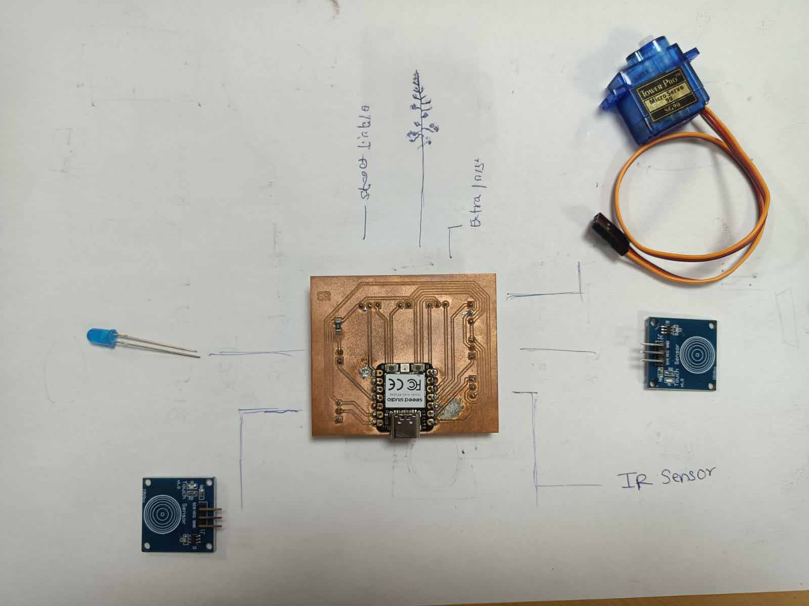
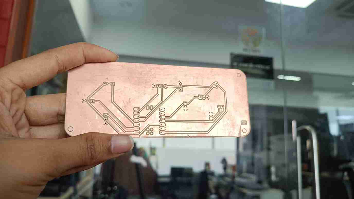
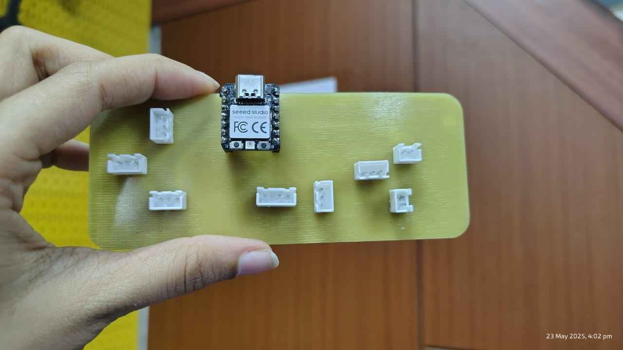
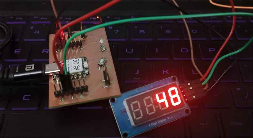
In the week of Eelctronics design I designed a PCB Board adhering to my Final project inputs and outputs. The documentation of PCB Designing is done in my Week 06: Electronics Design. Further, I milled the PCB in my Electronics Production week, The documentation of the development board and milling is done in my Week 08: Electronics Production. Below is the PCB that I milled during this week.
.jpg) Later, I soldering the XAIO RP2040 and a resistor to my PCB Board, I also attatched a JST pins to the PCB
Board and
and Soldered it.
Later, I soldering the XAIO RP2040 and a resistor to my PCB Board, I also attatched a JST pins to the PCB
Board and
and Soldered it.NOTE: The reason I used a JST Pin resistors was for the requirement of my Final Project.
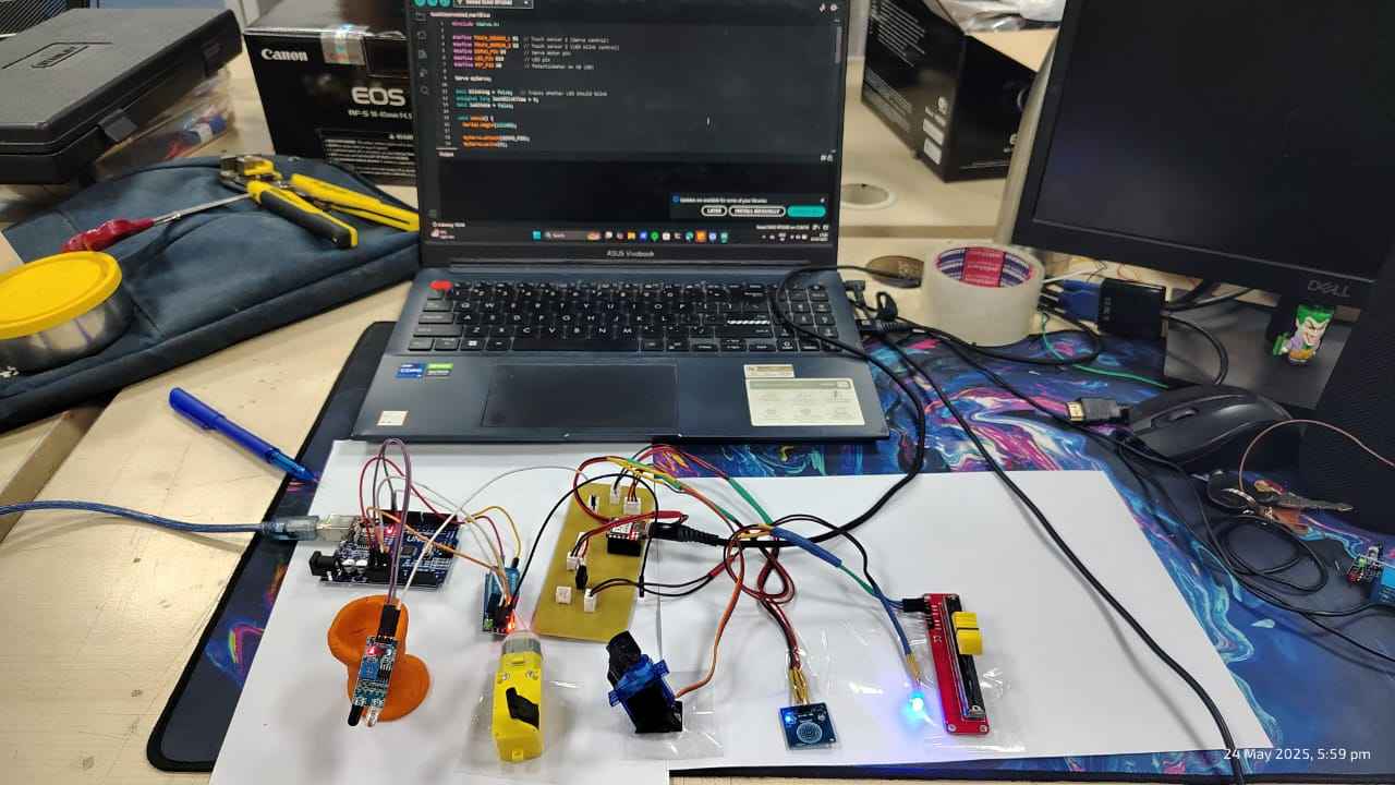
 Later, I soldered the SERVO MOTOR to the JST Wires.
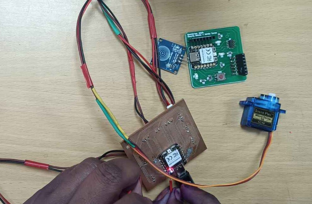
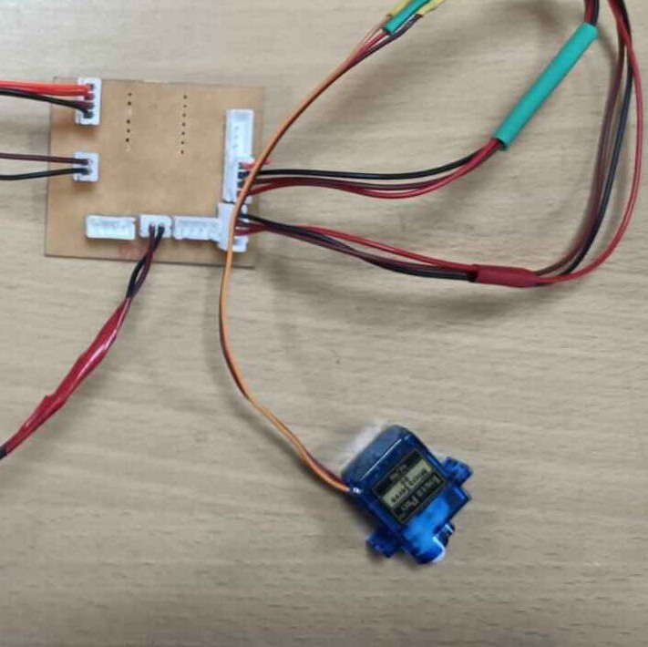 Once all was done I tested the working of the all the pinouts using an external connector.
Once I confirmed the functioning, I moved to the Coding part.
Once all was done I tested the working of the all the pinouts using an external connector.
Once I confirmed the functioning, I moved to the Coding part.
 As mention above, you will find a detailed documentation of the above in week 06 and week 08 of my
documentation.
As mention above, you will find a detailed documentation of the above in week 06 and week 08 of my
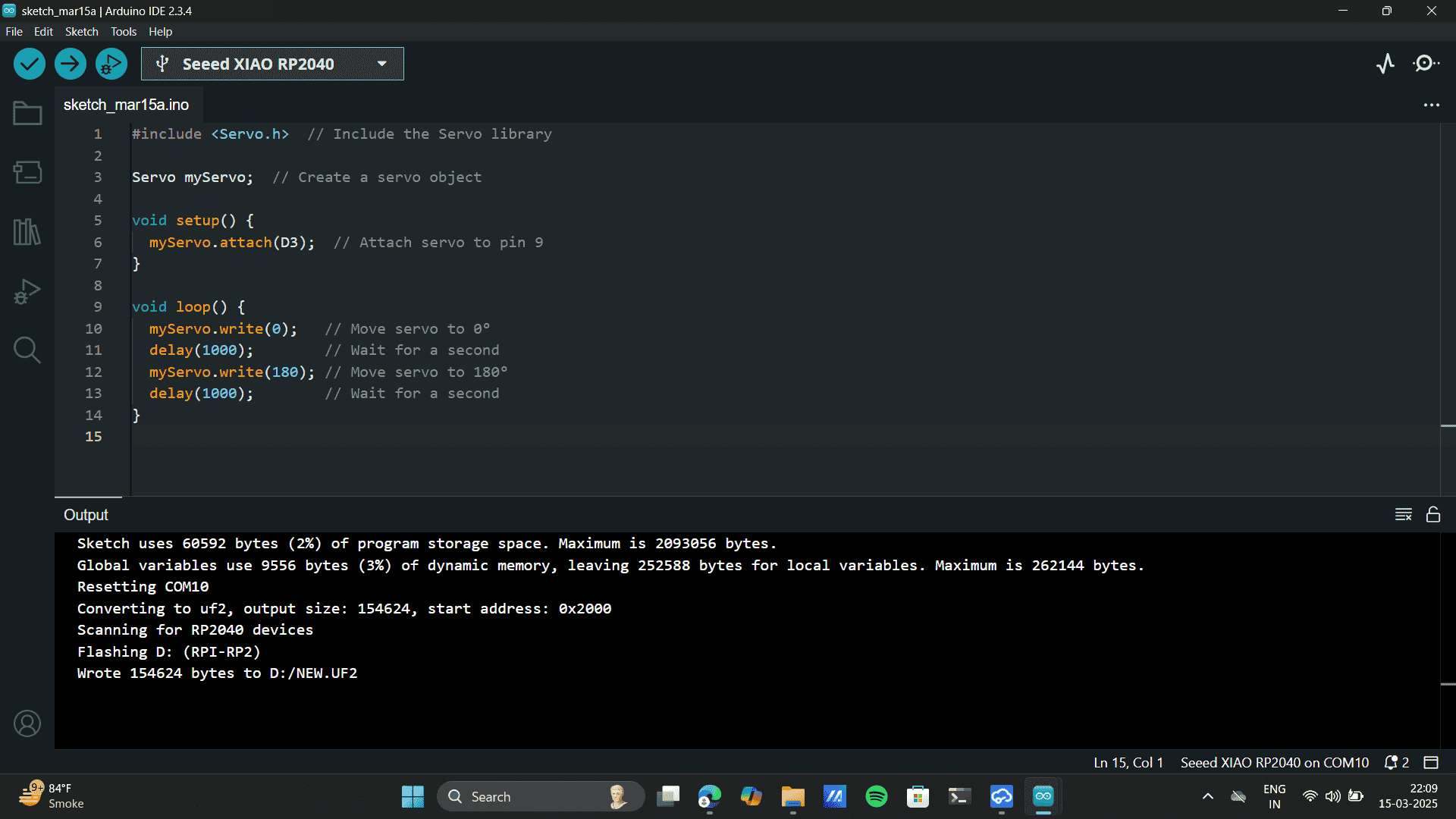
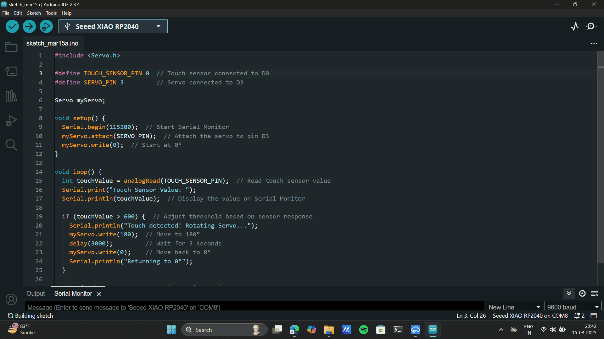
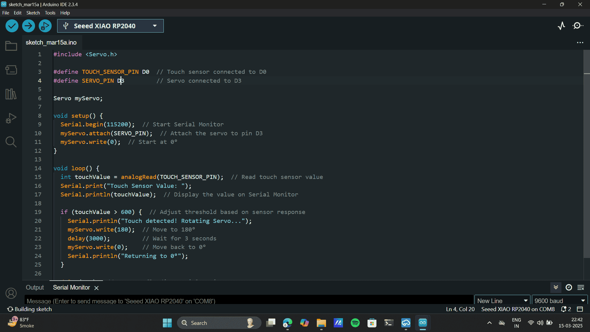
documentation.Coding: Part 1
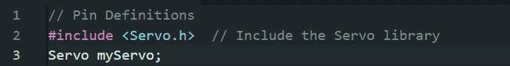
Used Ai prompt: Generate a simple code to run a servo.
#include // Include the Servo library
Servo myServo; // Create a servo object
void setup() {
myServo.attach(D3); // Attach servo to pin D3
}
void loop() {
myServo.write(0); // Move servo to 0°
delay(1000); // Wait for a second
myServo.write(180); // Move servo to 180°
delay(1000); // Wait for a second
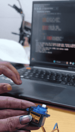
} Uploaded Code
Servo Motion sensed
.jpg)
.jpg)
.png)


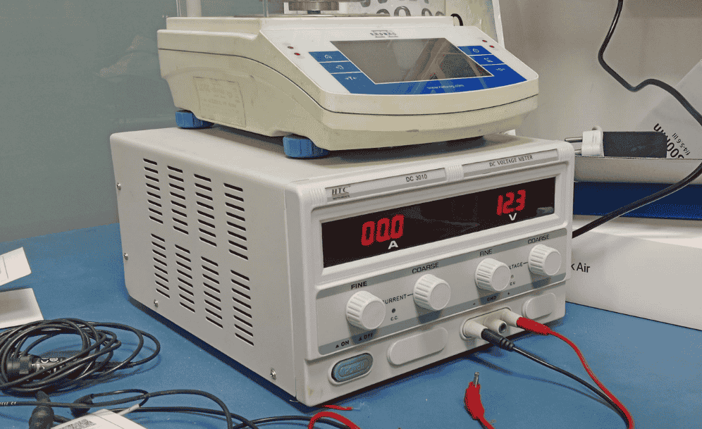
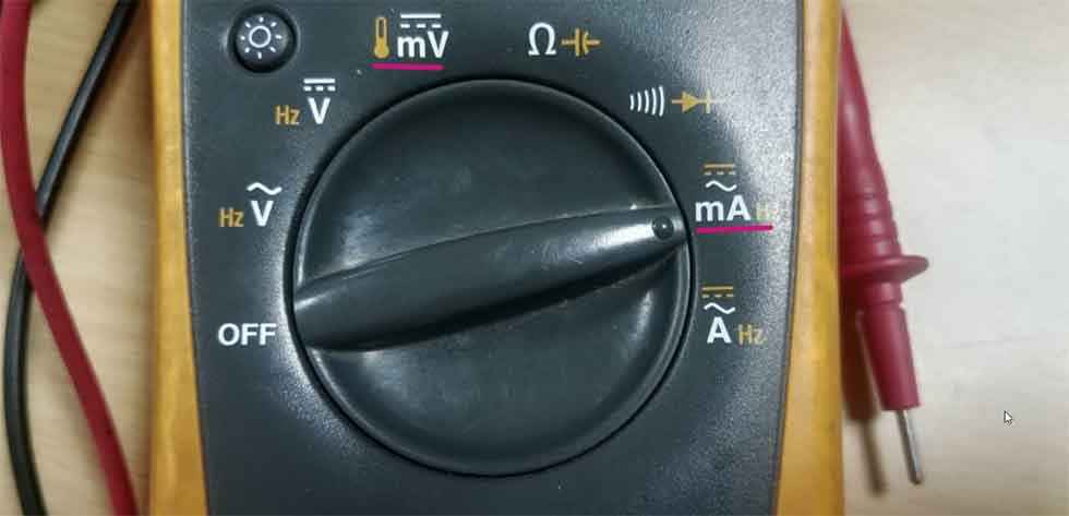
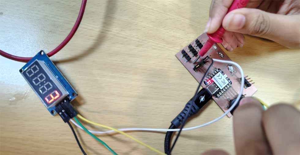
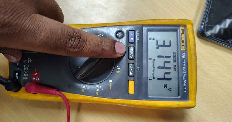
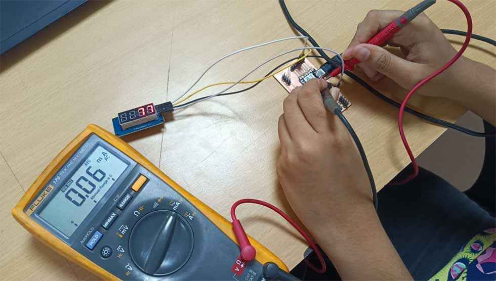 Power = Voltage × Current (P = VI),
Power Calculation
Power = Voltage × Current (P = VI),
Power Calculation