Assignment Brief:
- As a group probe an input device's analog levels and analyze its digital signals.
- Measure a parameter using a sensor. Integrate the sensor with a custom-designed microcontroller board and read its data.
Input Devices: Previously
Input devices are hardware components that allow users to enter data, commands, or signals into a computer or other electronic systems. They convert physical actions or external data into digital signals that the system can process.
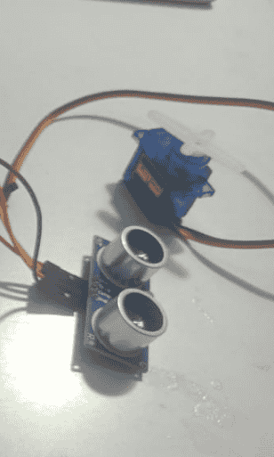
Personally, I had used an ultra sonic sensor in on eof the mini projects I did a year age, which was the first time I understood basics of Input and output devices. So, the first input device I used was an ultra sonic sensor. I also used a servo motor as an output. The project was a simple game, inspired by the mobile application game of Talking Tom, I built a frowning Cat, who uses a knife whenever a user comes near.
.png)
Input Devices: Week 09
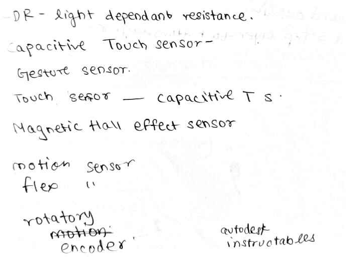
Later, to understand the existing Input devices, I referred to the internet and chat gpt to leanr about the existing Input devices and their range of study. To learn more about sensors you can visit Autodesk Instructables to find DIY projects related to these sensors.
.jpg)
In this week, as I learnt about different sensors, I analysed the sensor that I could incorporate in my Final Project. After talking to my mentors Pranav Gawde and Jesal Mehta, I finalized the sensors that could help my final project idea. As per this and as an explorative lense I chose the sensors I would use for this week. That is:
- Touch sensor
- Accelorometer MP6040 6-axis (This I tried for explorative purpose.)
Touch Sensor
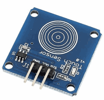
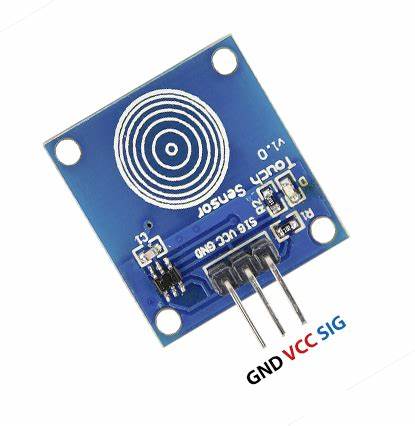
For better understanding of how I went through the project, lets go step by step. First Lets understand the Touch sensor. A touch sensor detects physical contact (like a finger touch) and converts it into an electrical signal. It is commonly used in touchscreens, buttons, and interactive devices.
| Touch Sensor Type | Working Principle | Applications | Advantages | Limitations |
|---|---|---|---|---|
| Capacitive | Measures changes in capacitance when a conductive object (finger) disrupts the electric field. | Smartphones, touchpads, control panels, tablets. | High sensitivity, multi-touch support, durable, scratch-resistant. | Doesn't work with non-conductive objects (gloves, stylus), affected by water/humidity, higher cost. |
| Resistive | Two conductive layers separated by a gap touch when pressed, completing a circuit. | ATMs, industrial touchscreens, older touch devices. | Works with any object (stylus, gloves), lower cost, durable in harsh conditions. | Less sensitive, no multi-touch support, prone to wear and tear. |
| Infrared | Uses IR LEDs and photodetectors; touch blocks the infrared beam. | Interactive kiosks, public touch displays, medical devices. | Works with any material, long lifespan, high durability. | Can be affected by dirt, dust, and strong ambient light. |
| Piezoelectric | Generates a small electric charge when pressure is applied. | Industrial applications, harsh environments, touch-sensitive musical instruments. | High durability, works in extreme conditions, no need for conductive materials. | Expensive, requires strong force to activate. |
| Optical | Uses cameras or light sensors to detect touch disruptions. | Large interactive displays, multi-touch tables, high-end kiosks. | High accuracy, supports multi-touch, durable. | Expensive, bulky, requires calibration. |
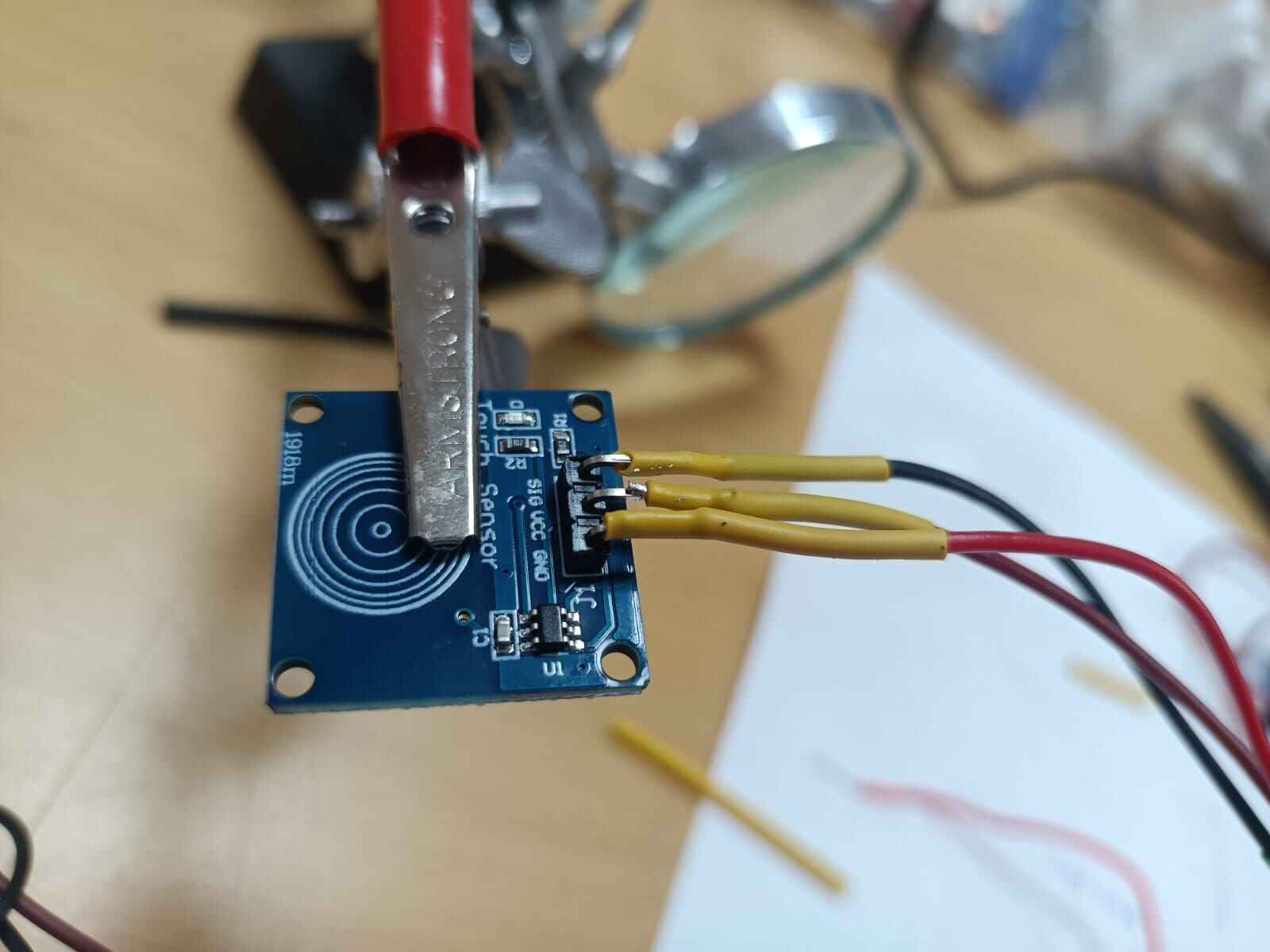
I used the a capacitive touch sensorwhich detects touch by measuring changes in electrical capacitance. It consists of a conductive surface and an electric field. When a conductive object (like a human finger) comes close, it disrupts the field, changing the capacitance. Surface Capacitive - Uses a thin conductive layer where a small current flows upon touch.
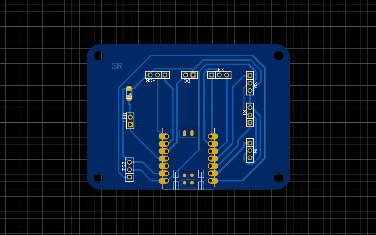
Design and Fabrication: refer to
Week 06:
Electronics Design.
Pcb production: refer to
Week 08: PCB Production
.jpg)
Relevance to Final Project
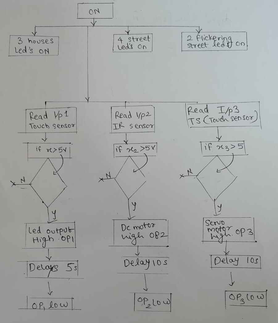
Coding part: Made flow chart and used Chatgpt Ai prompt: Give a code for rp2040 connection on aurdino ide for the above connection. I was mesmerized by the code output that i received from chatgpt. As I read the code. the code read every bit well.
Didn't read USB COM
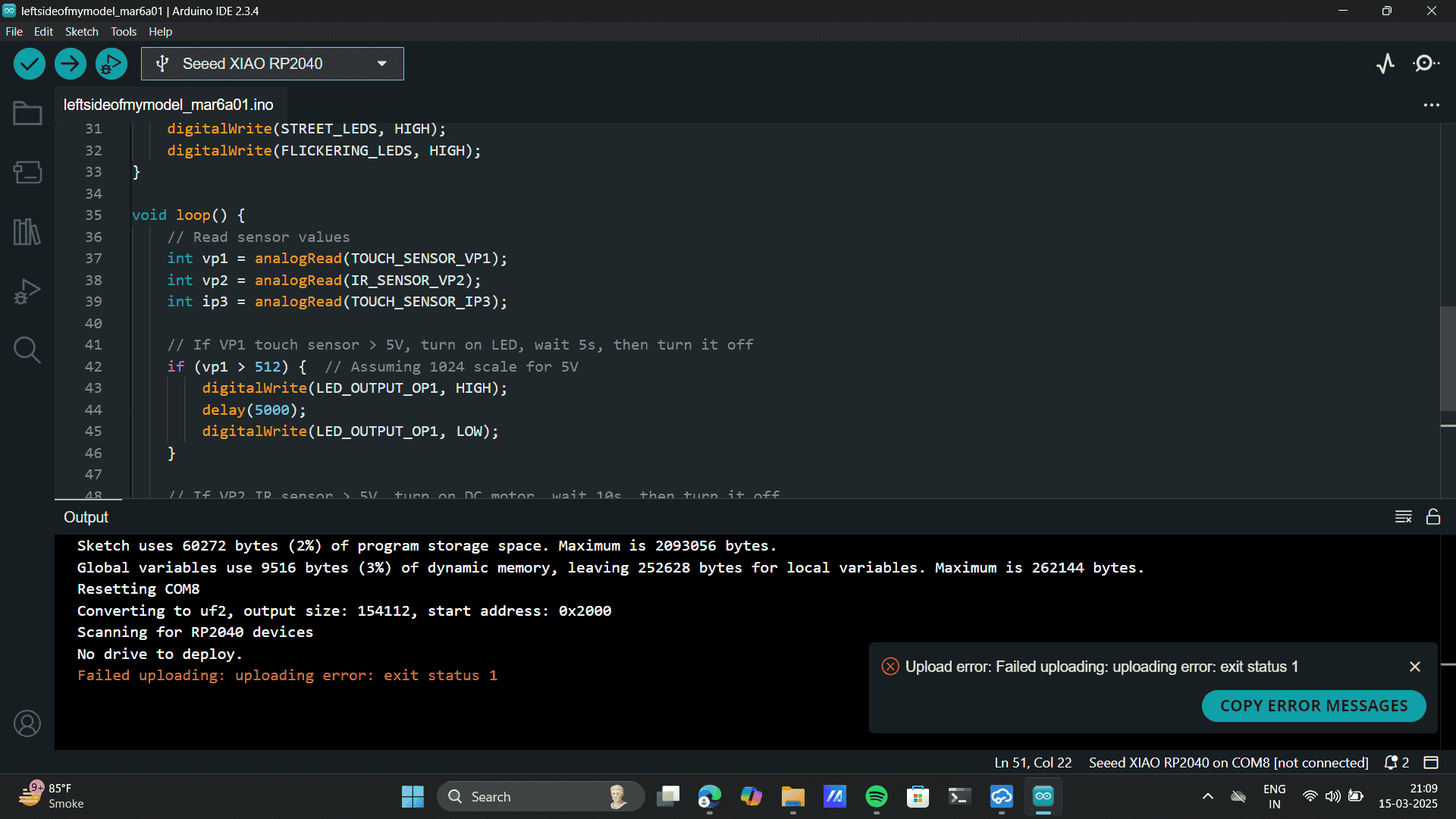
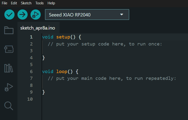
Selected the seed xaio rp2040 board and selected port.

Learnings: The code was pushed succesfully but didnt work perfectly. I realised the pin numbers needed to be changes. The biggest issue with the code was the aurdino Uno Library. The code that ai generated didnt include the libraried to run the code.
Touch Sensor
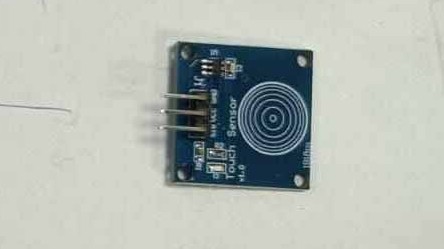
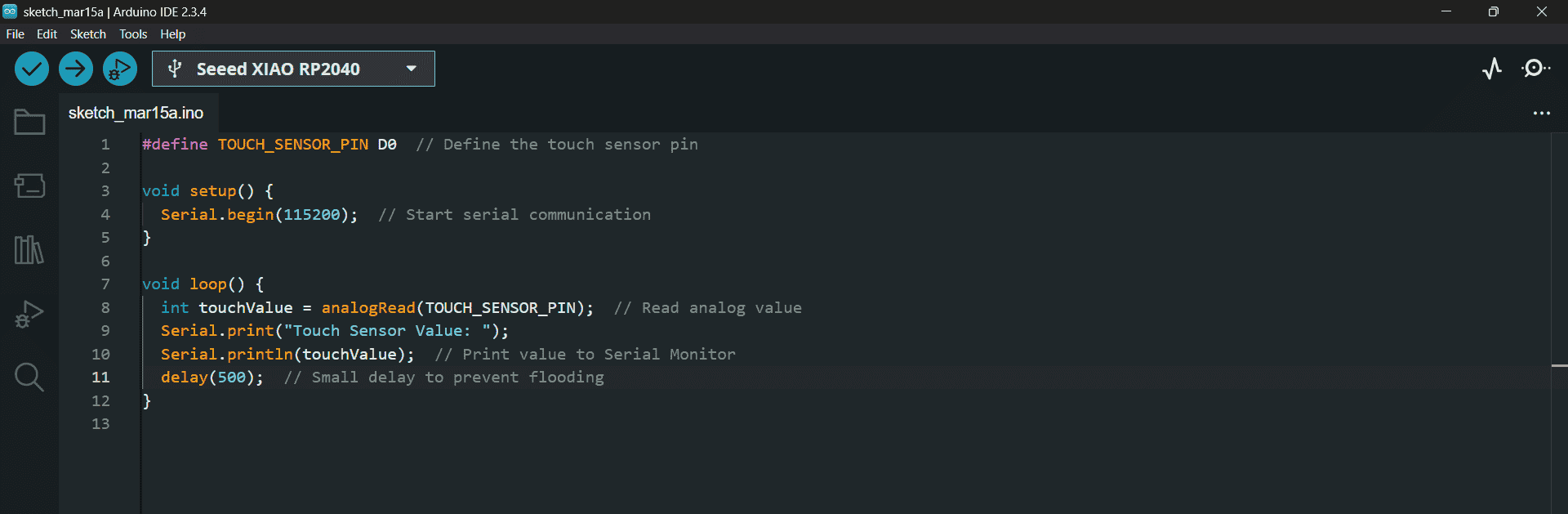
To understand the structure of complex code, I decided to first explore its smaller components. I started with the touch sensor and used the Serial Monitor to observe its raw analog output. By reading values from pin D0 on the Seeed XIAO RP2040, I could see how the sensor responded to touch in real time.
Later, I chose to go step by step to give the code. Fist I generated the code for the touch sensor.I used code for Xaio and mentioned pin numbers and other specifications as well. Ai prompt: Generate a code to monitor input signal for a touch sensor connected to pin D0 on Xaio RP2040. Note as per New updates on Arduino IDE, the pin cofiguration for pin 0 is D0.
#define TOUCH_SENSOR_PIN D0  // Define the touch sensor pin
void setup() {
    Serial.begin(115200);  // Start serial communication
}
void loop() {
    int touchValue = analogRead(TOUCH_SENSOR_PIN);  // Read analog value
    Serial.print("Touch Sensor Value: ");
    Serial.println(touchValue);  // Print value to Serial Monitor
    delay(500);  // Small delay to prevent flooding
} 
The values bounce between ~6 and 1023, suggesting: The sensor is not touched (values near 6). The sensor is fully triggered/touched (1023 = max analogRead).
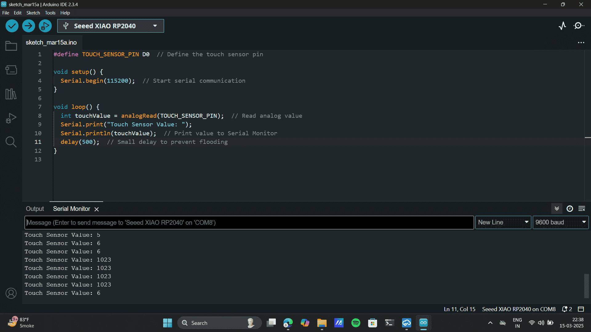
Learnings: This allowed me to observe real-time sensor data and understand how it behaves under different conditions—such as when it is touched versus untouched. I monitored the value fluctuations, which helped me identify key thresholds and assess the consistency of the sensor’s output.
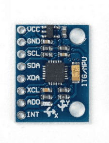
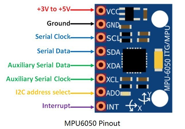
Accelerometer MP6040 6-axis
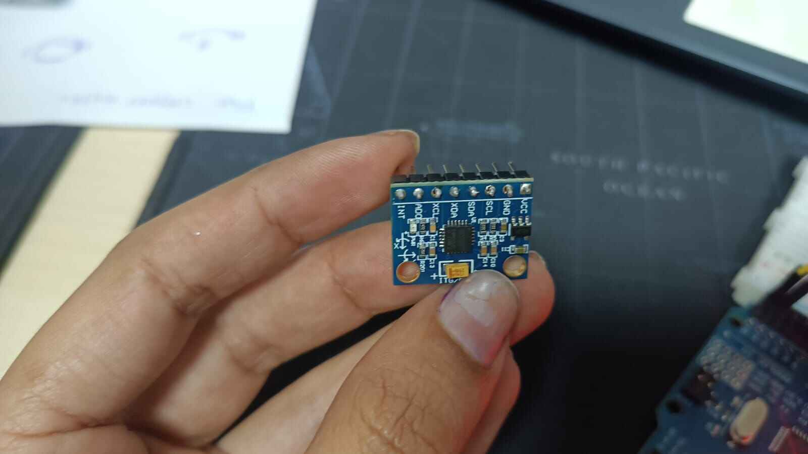
Wiring (I2C Protocol)
VCC → 3.3V or 5V
SDA → A4 (on Uno/Nano)
SCL → A5 (on Uno/Nano)
Common GND
Code set-up
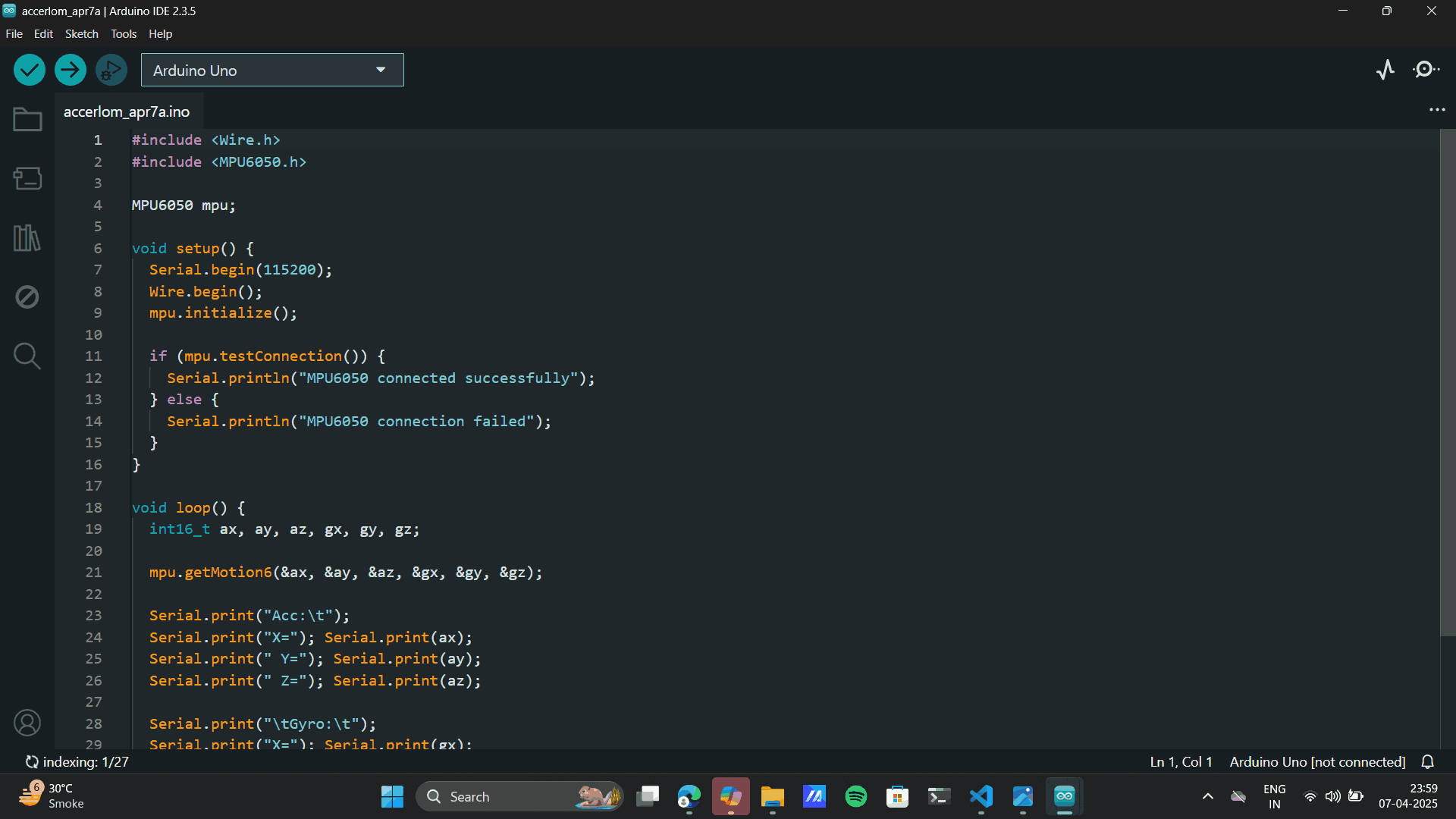
                    #include Wire.h>
                    #include MPU6050.h>

                    MPU6050 mpu;

                    void setup() {
                      Serial.begin(115200);
                      Wire.begin();
                      mpu.initialize();

                      if (mpu.testConnection()) {
                        Serial.println("MPU6050 connected successfully");
                      } else {
                        Serial.println("MPU6050 connection failed");
                      }
                    }

                    void loop() {
                      int16_t ax, ay, az, gx, gy, gz;

                      mpu.getMotion6(&ax, &ay, &az, &gx, &gy, &gz);

                      Serial.print("Acc:\t");
                      Serial.print("X="); Serial.print(ax);
                      Serial.print(" Y="); Serial.print(ay);
                      Serial.print(" Z="); Serial.print(az);

                      Serial.print("\tGyro:\t");
                      Serial.print("X="); Serial.print(gx);
                      Serial.print(" Y="); Serial.print(gy);
                      Serial.print(" Z="); Serial.println(gz);

                      delay(500);
                    }
The serial monitor displays live sensor data being streamed from the MPU-6050 module interfaced with an Arduino board. This real-time feedback helps validate sensor functionality and observe changes in orientation, motion, and temperature.
Quentorres Board
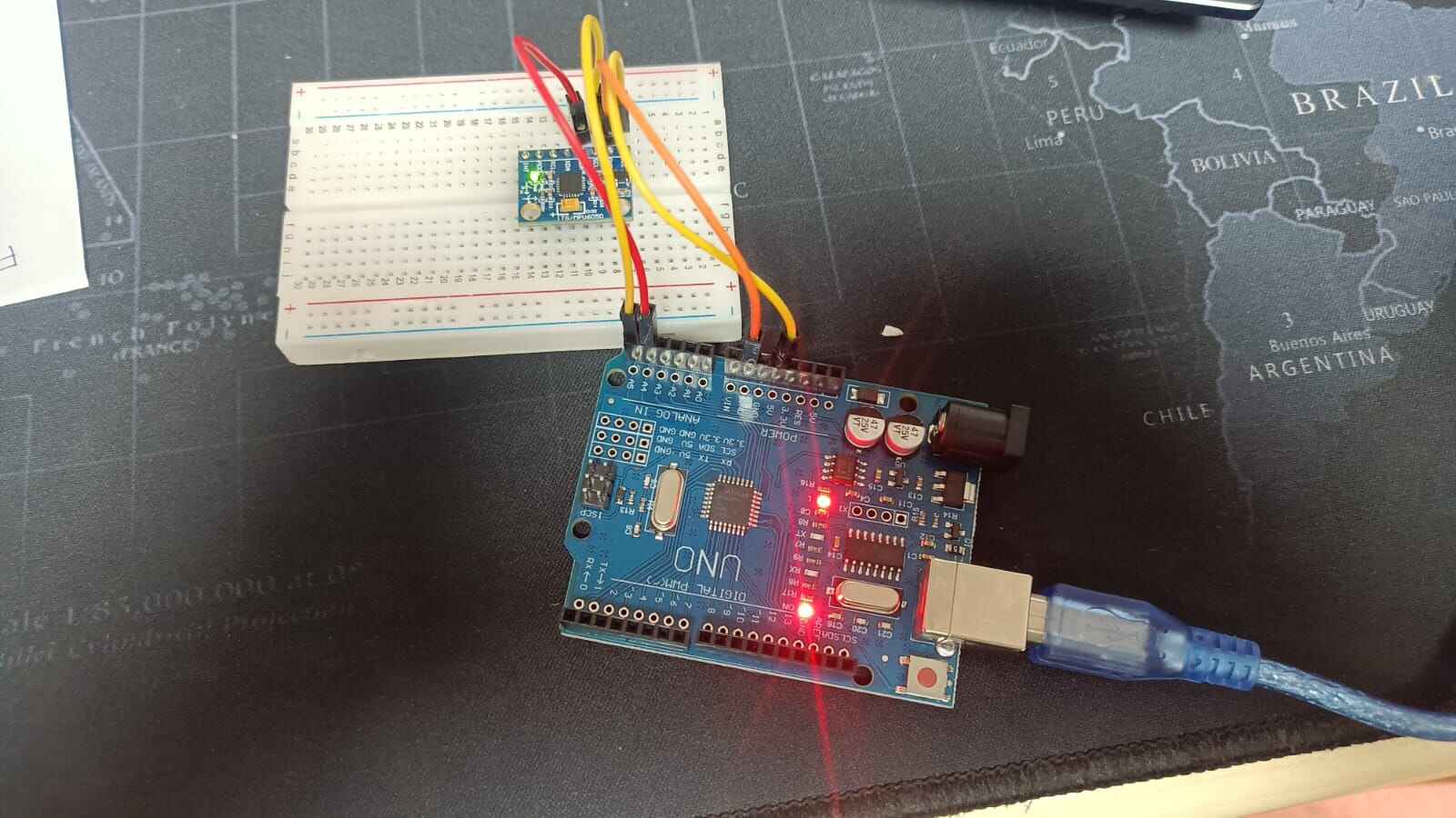
In the Similar manner I tried using the quentorres board to monitor the Accelorometer.
Referring to the belove connections.
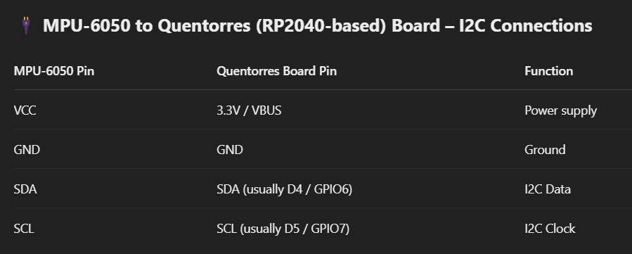
.jpg)
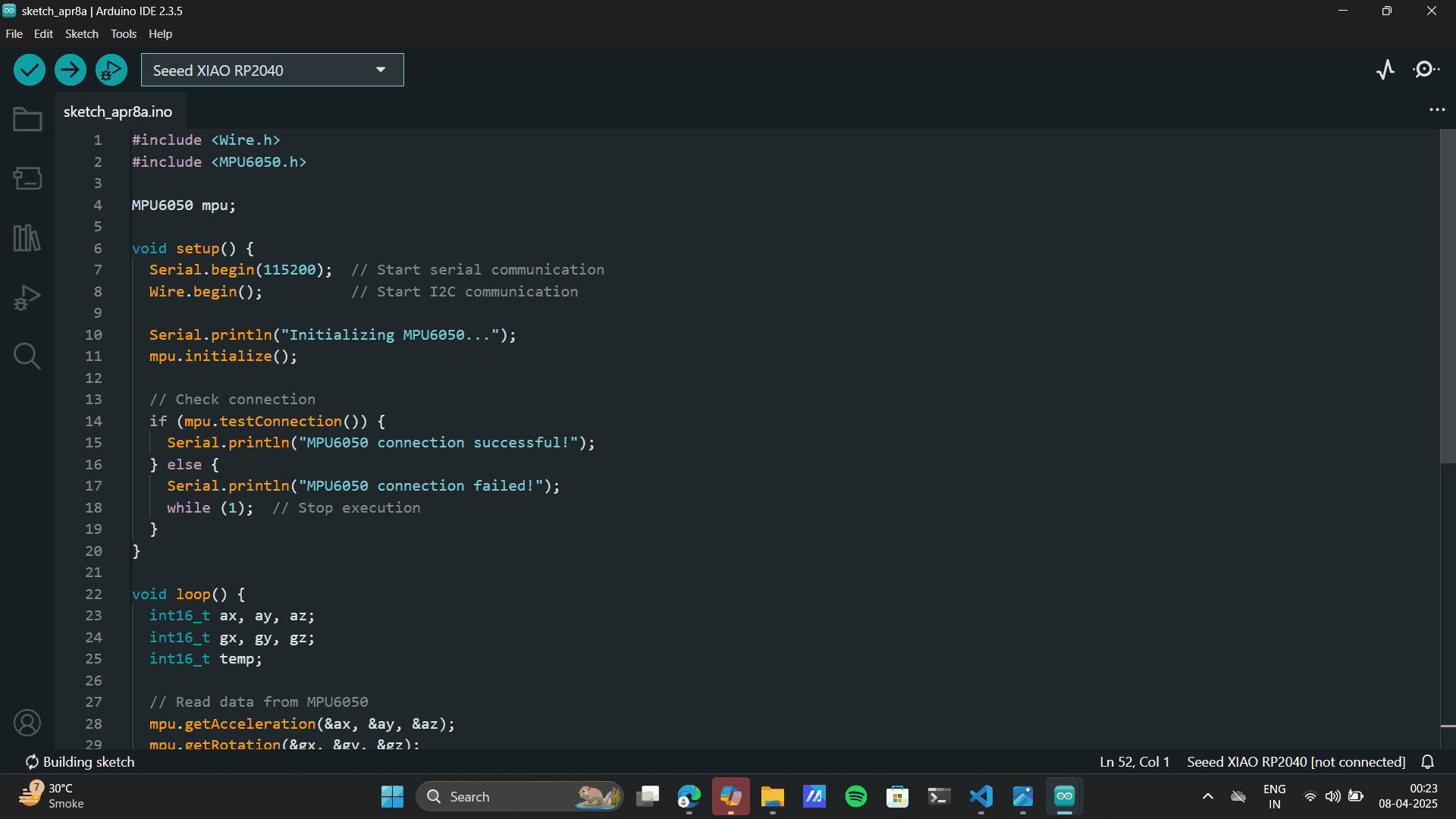
#include
    #include

    MPU6050 mpu;

    void setup() {
      Serial.begin(115200);  // Start serial communication
      Wire.begin();          // Start I2C communication

      Serial.println("Initializing MPU6050...");
      mpu.initialize();

      // Check connection
      if (mpu.testConnection()) {
        Serial.println("MPU6050 connection successful!");
      } else {
        Serial.println("MPU6050 connection failed!");
        while (1);  // Stop execution
      }
    }

    void loop() {
      int16_t ax, ay, az;
      int16_t gx, gy, gz;
      int16_t temp;

      // Read data from MPU6050
      mpu.getAcceleration(&ax, &ay, &az);
      mpu.getRotation(&gx, &gy, &gz);
      temp = mpu.getTemperature();

      // Print values to Serial Monitor
      Serial.print("Acceleration: X=");
      Serial.print(ax);
      Serial.print(" Y=");
      Serial.print(ay);
      Serial.print(" Z=");
      Serial.print(az);

      Serial.print(" | Temperature: ");
      Serial.print(temp / 340.00 + 36.53);  // Convert raw temp to °C

      Serial.print(" | Gyroscope: X=");
      Serial.print(gx);
      Serial.print(" Y=");
      Serial.print(gy);
      Serial.print(" Z=");
      Serial.println(gz);

      delay(500);  // Wait half a second
    }
Code Failed Uploading,
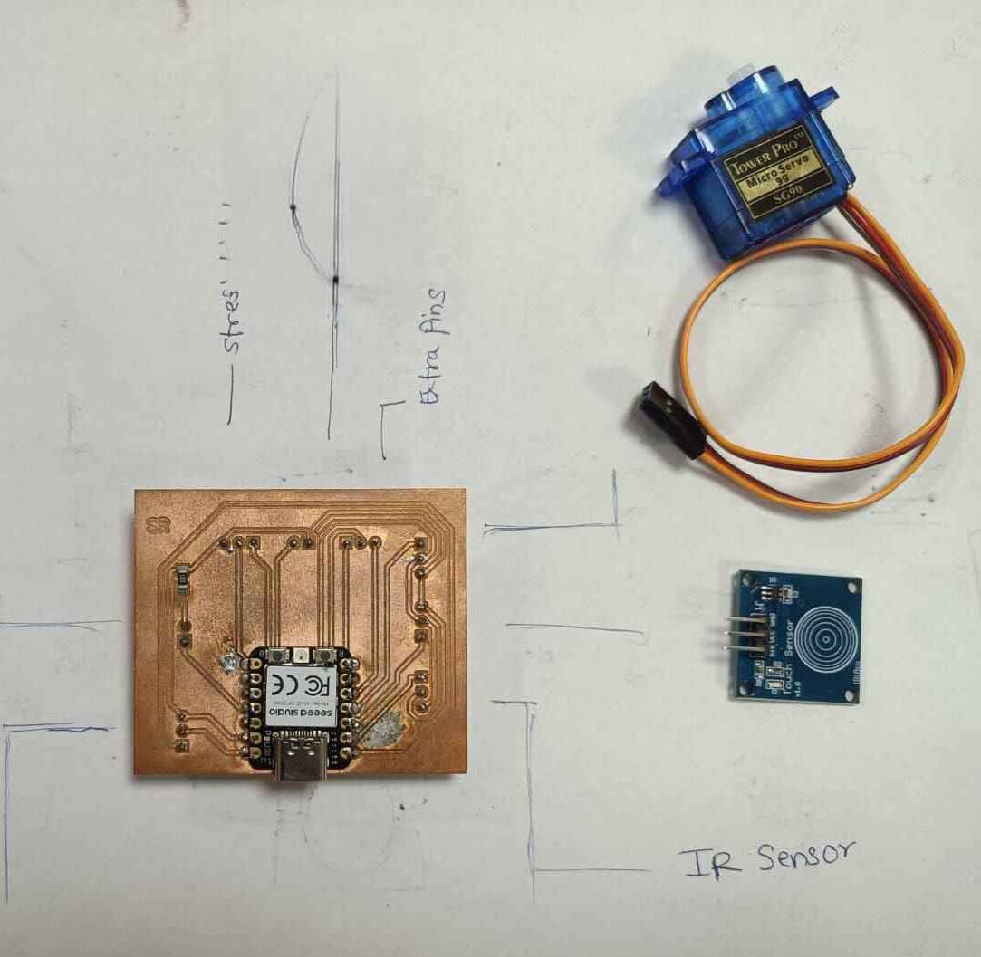
Learnings: I burnt the Xaio on the Quentorres board, I also tried the same code on my own
PCB board assuming
that the Quentorres board might be having errors and burnt it as well. Next, a heavy learning lesson
came by my way.
While using the RP2040 Remember:
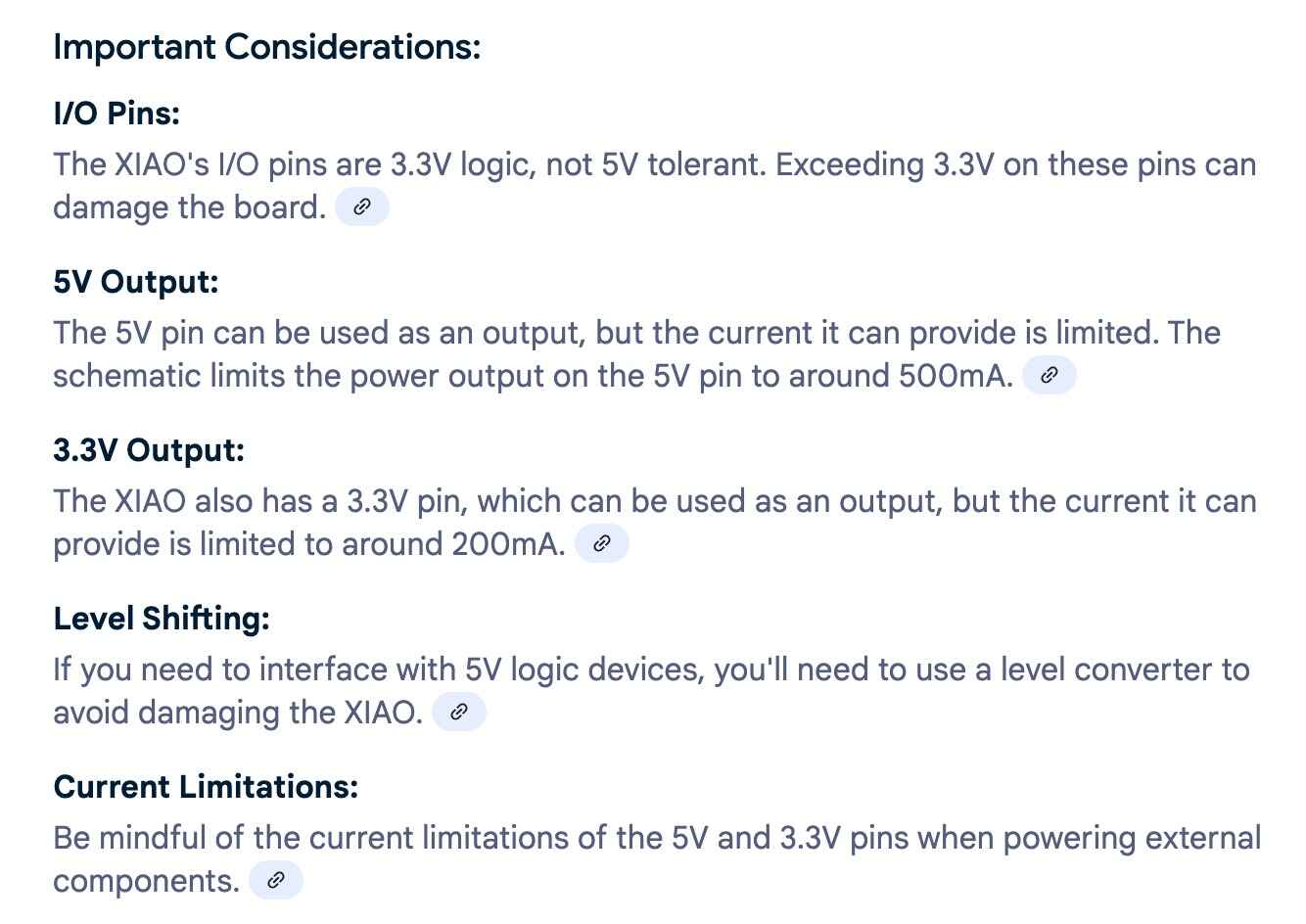
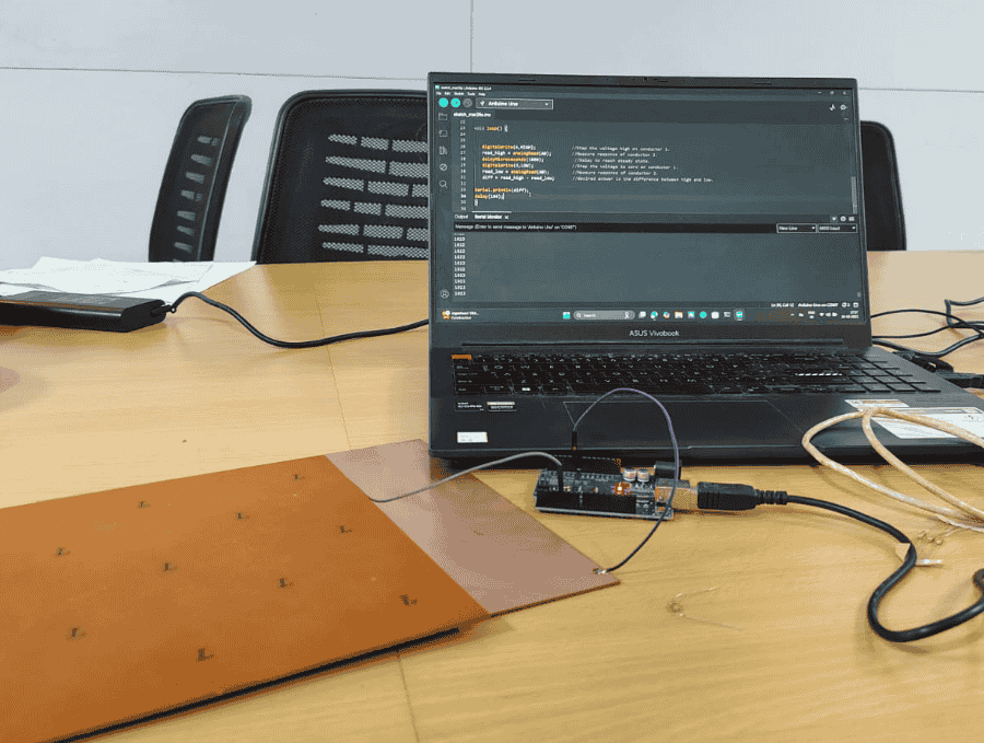
Step Response
My professor's
Pranav Gawde and
Jesal Mehta guided and taught me the basics of step response.
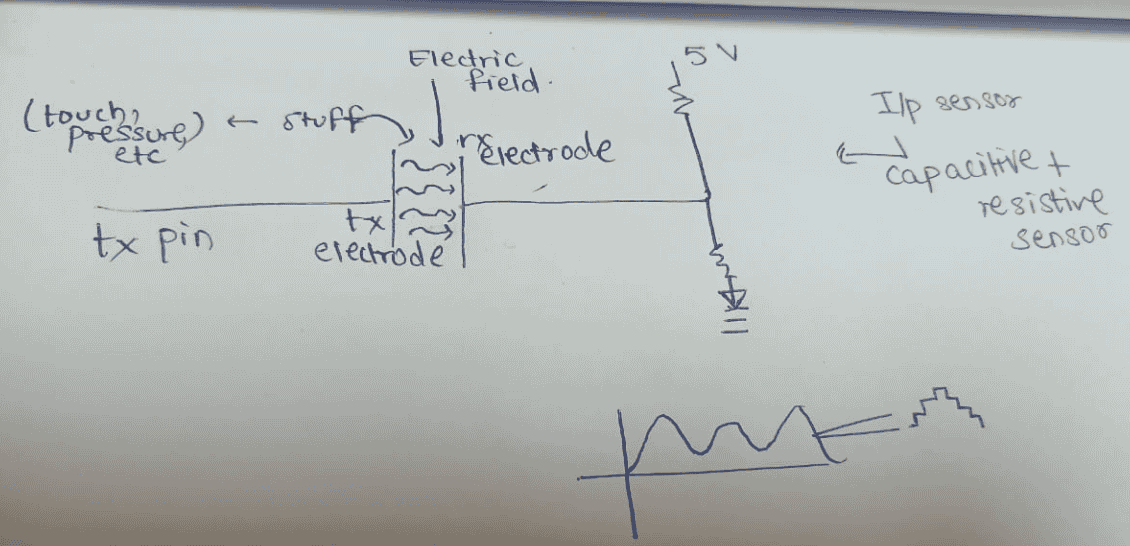
Sensing with Step Response (transmit-receive, or tx-rx)
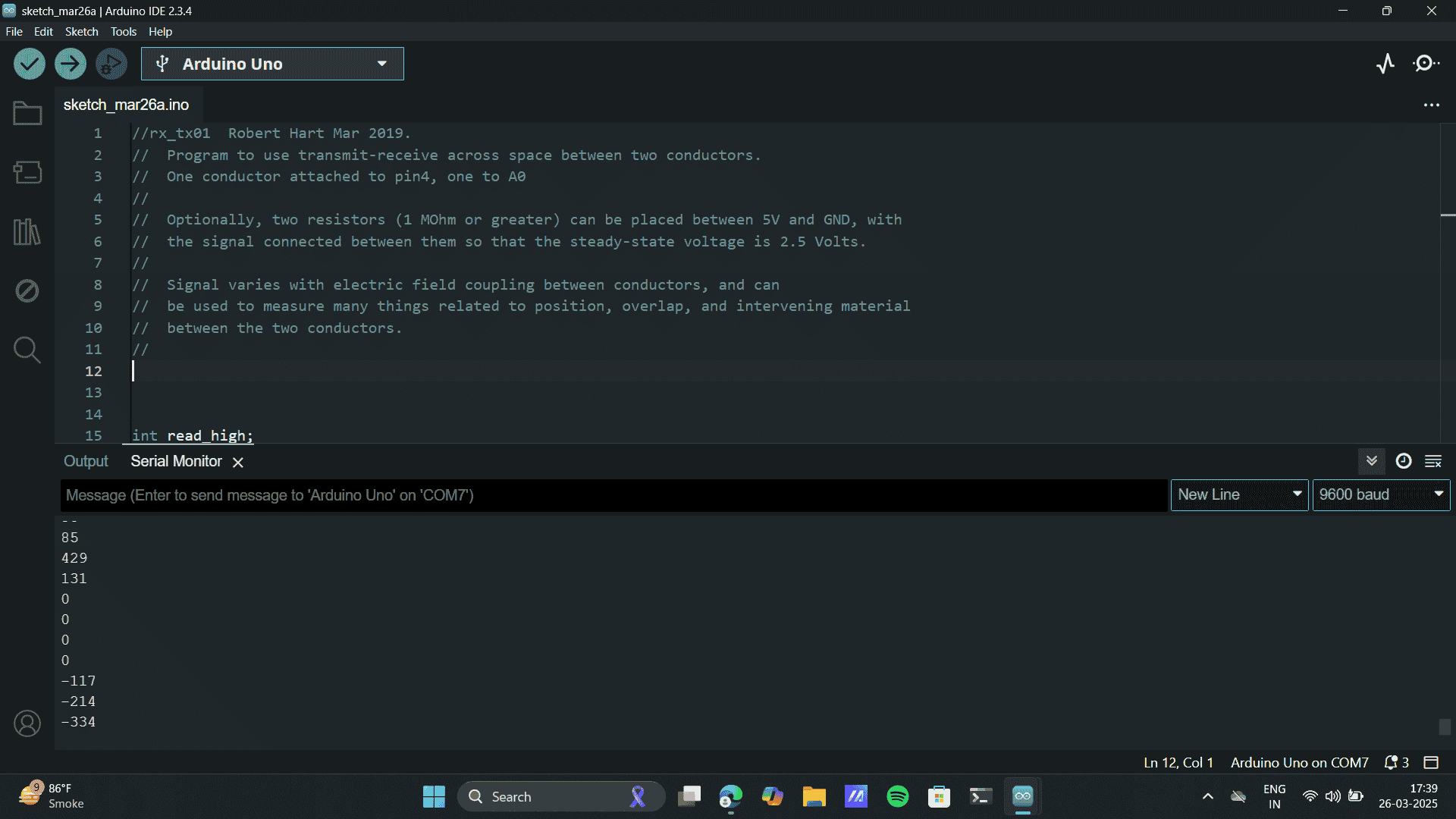
//rx_tx01 Robert Hart Mar 2019.
// Program to use transmit-receive across space between two conductors.
// One conductor attached to pin4, one to A0
//
// Optionally, two resistors (1 MOhm or greater) can be placed between 5V and GND, with
// the signal connected between them so that the steady-state voltage is 2.5 Volts.
//
// Signal varies with electric field coupling between conductors, and can
// be used to measure many things related to position, overlap, and intervening material
// between the two conductors.
//
int read_high;
int read_low;
int diff;
void setup() {
pinMode(4,OUTPUT); //Pin 4 provides the voltage step
Serial.begin(9600);
}
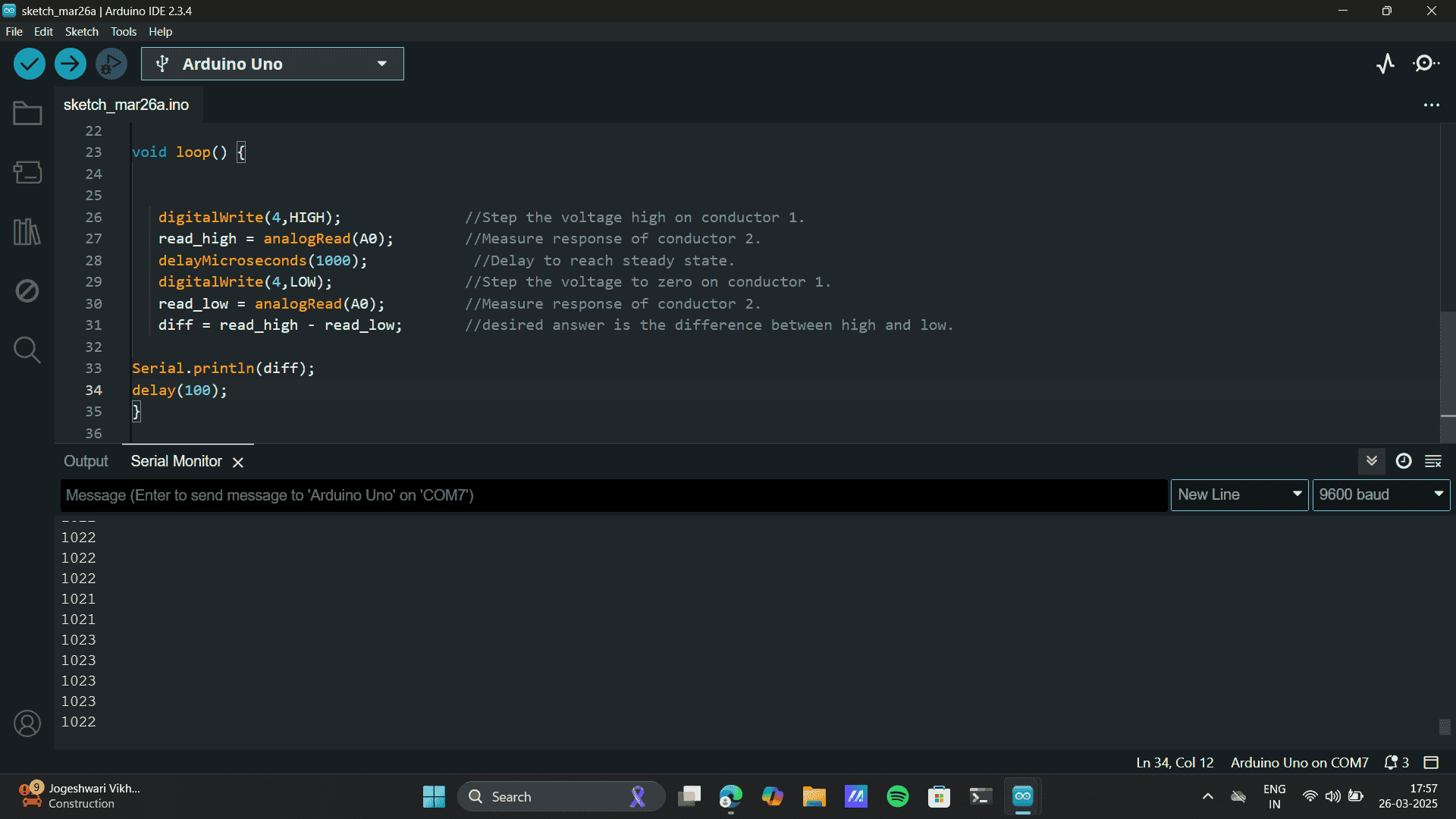
void loop() {
digitalWrite(4,HIGH); //Step the voltage high on conductor 1.
read_high = analogRead(A0); //Measure response of conductor 2.
delayMicroseconds(100); //Delay to reach steady state.
digitalWrite(4,LOW); //Step the voltage to zero on conductor 1.
read_low = analogRead(A0); //Measure response of conductor 2.
diff = read_high - read_low; //desired answer is the difference between high and low.
Serial.println(diff);
//delay(100);
}
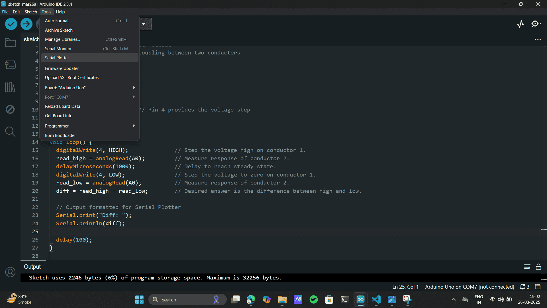
    // rx_tx01  Robert Hart Mar 2019.
// Modified for Serial Plotter output
// Measures electric field coupling between two conductors.

int read_high;
int read_low;
int diff;

void setup() {
  pinMode(4, OUTPUT);      // Pin 4 provides the voltage step
  Serial.begin(9600);
}

void loop() {
  digitalWrite(4, HIGH);              // Step the voltage high on conductor 1.
  read_high = analogRead(A0);         // Measure response of conductor 2.
  delayMicroseconds(1000);            // Delay to reach steady state.
  digitalWrite(4, LOW);               // Step the voltage to zero on conductor 1.
  read_low = analogRead(A0);          // Measure response of conductor 2.
  diff = read_high - read_low;        // Desired answer is the difference between high and low.

  // Output formatted for Serial Plotter
  Serial.print("Diff: ");
  Serial.println(diff);

  delay(100);
}
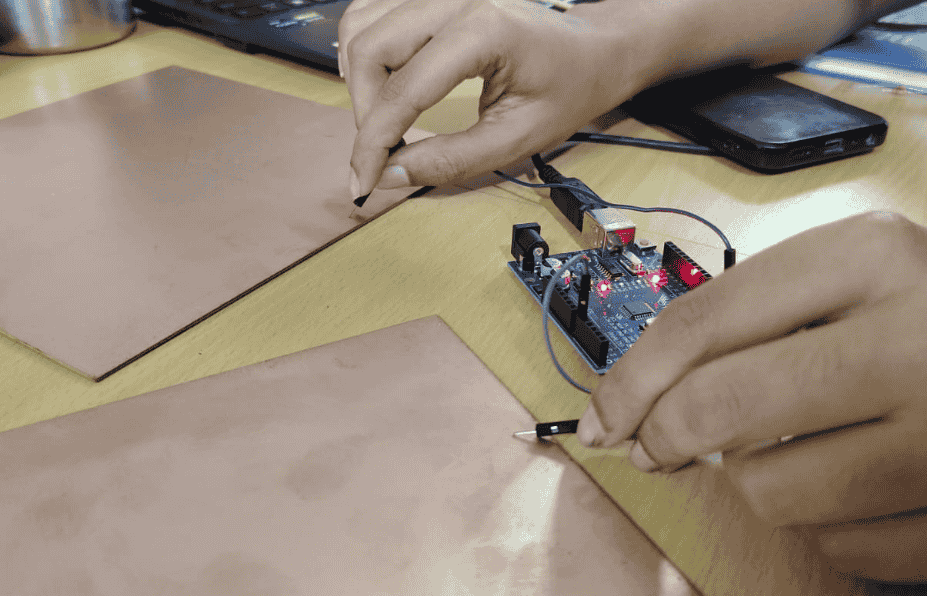
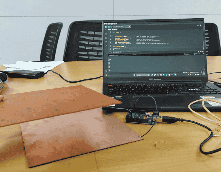
When the copper plates are away.
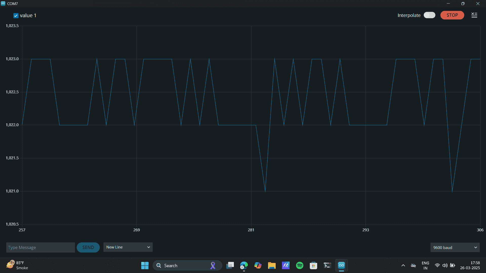
When the copper plates touch together.
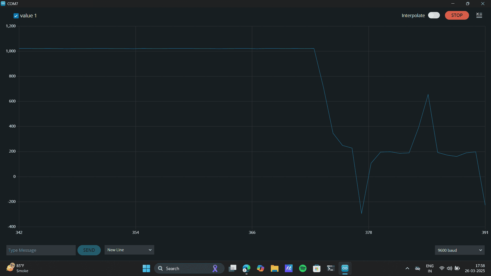
Learnings:
1. Understanding Pressure Sensors: A pressure sensor works by converting mechanical pressure (force) into an electrical signal. When force is applied, the internal structure (usually piezoresistive, capacitive, or resistive) changes its properties like resistance or capacitance. This change can be measured and mapped to a value of pressure or force using simple circuitry or microcontroller input.
2. Electric Field Generation Concept: Applying pressure can alter the electric field between materials, especially in capacitive sensors. In capacitive sensing: Two conductive plates with a dielectric in between form a capacitor. When pressure changes the distance between plates or compresses the dielectric, the capacitance changes. This variation can be detected as a signal using an analog pin on a microcontroller like Arduino.
3. Compact Design Thinking: To make pressure sensors work in compact designs, I understood: Use thin, flexible materials (like Velostat, piezo films, or conductive foam). Integrate directly into wearables or layered components like insoles, bands, or straps. Minimize circuit complexity by using modular microcontrollers and I2C or analog signals to read values.
Group assignment
Check out this week’s Input Devices group assignment on Mihir's documentation site here
This week’s group assignment involved exploring the analog and digital signals from an input device. We used the HC-SR04 ultrasonic sensor and monitored its output through the Serial Plotter in the Arduino IDE. As we moved objects closer to or farther from the sensor, we observed fluctuations in the waveform. The sensor readings varied based on distance—closer objects produced higher amplitude values. This real-time visual feedback gave us a clearer understanding of how the sensor detects proximity and how its data can be interpreted for various applications.
Project files
Step response graph codeStep response serial code
Arduino to Accelerometer code
Xaio to Accelerometer code
Image Links
Image Link.Image Link.
Image Link.
Image Link.