Week 14: Interface and Application Programming
Introduction
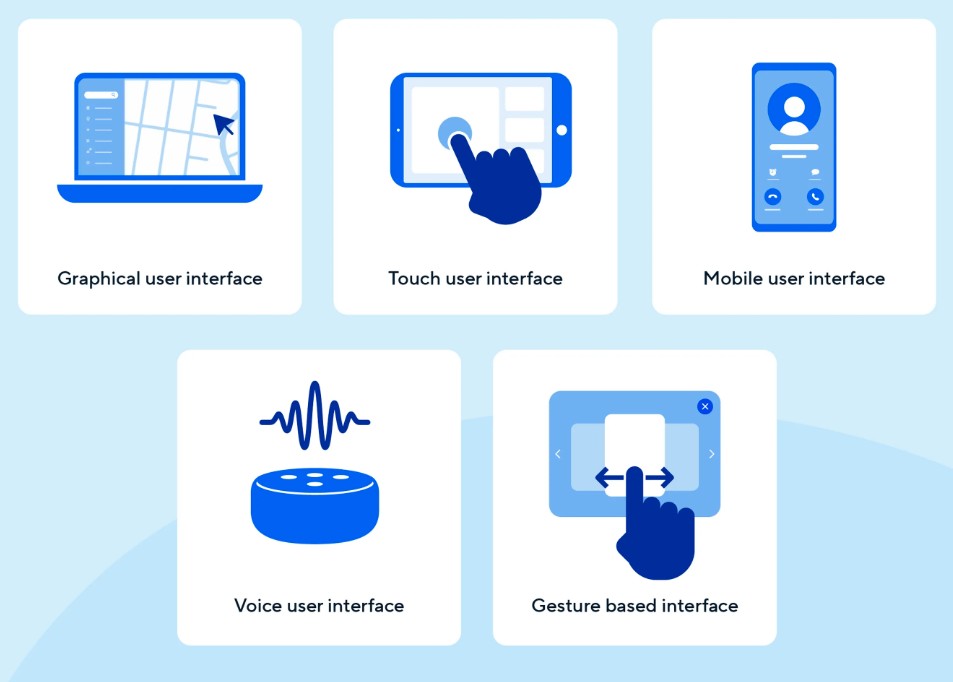
In the world of digital systems and embedded electronics, a user interface (UI) is a critical component that allows humans to interact with machines. Interfaces can be physical (e.g., buttons, switches), graphical (e.g., software windows, sliders), or even auditory (e.g., voice commands). Their main purpose is to make technology accessible and easy to control for users.
In the context of embedded systems—such as robotics, wearables, or IoT devices—interfaces allow users to send commands, receive feedback, and control devices in real time. Without an interface, most embedded devices operate autonomously or require programming knowledge to modify their behavior.
For instance, imagine an exoskeleton suit designed to assist movement. Without a user interface, changing the servo angle or behavior would require re-uploading Arduino code. But with a graphical interface, a user can simply drag a slider or click a button to achieve the same result instantly.
Group Assignment
You can find the group assignment for Interface and Application Programming week at the following link: Group Assignment - Fab Lab Puebla.
During this week of the Fab Academy, I explored how to build such interfaces using PyQt5, a powerful Python library for creating desktop GUI applications. I developed an application that communicates with my custom microcontroller board via USB Serial to control a servo motor and LED. This is an essential foundation for my final project—a functional exoskeleton that requires precise and user-friendly motor control.
Objective
The objective is to write a Python application using PyQt that communicates with my custom-made microcontroller board to control a servo motor and an LED. This experience will help me understand how to create real-time interactions between a user and hardware, an essential component for my final project: a functional exoskeleton that uses servos to assist movement.
Hardware: My Custom Board
For this assignment, I used both the ESP32-C3 (fabricated in Week 8) and the XIAO RP2040 board. The RP2040 was used to test finer servo movement using the D0 pin at 9600 bauds.
Materials
- Custom ESP32-C3 board
- Seeed XIAO RP2040 board
- Micro Servo motor (SG90)
- Jumper wires
- USB-C cable
- PC with Python and PyQt5 installed
Steps
- Connect the servo to a PWM pin (D3 on ESP32 or D0 on RP2040)
- Connect LED to a digital pin via a resistor
- Write Arduino code to control the devices via Serial
- Build a PyQt5 GUI to send serial commands
- Test interactions in real-time
About PyQt and CMD
Initially, I had trouble running the PyQt GUI from VSCode—it would not display the window correctly. This was likely due to virtual environment conflicts or terminal rendering issues.
I solved it by running everything from the Windows Command Prompt (CMD), which worked perfectly.
Interface Design
I designed the graphical user interface using PyQt5. To speed up the process, I used Qt Designer, which allows the creation of GUI layouts by dragging and dropping widgets.
- I created a main window with a horizontal
QSliderto control the servo angle. - A
QLabeldisplays the current angle value dynamically. - A
QPushButtonresets the slider back to 90°. - The UI layout was saved as a
.uifile and converted into Python code usingpyuic5.
This visual approach made it easier to integrate GUI controls with the backend logic.
Communication Between Hardware and GUI
The GUI and the microcontroller communicate through serial communication (UART) over USB. Here's how it works:
- Python opens a serial connection on
COM4at 9600 baud (or 115200 if using ESP32). - When the user adjusts the slider, the GUI sends the angle as a string followed by
\n. - The Arduino code listens for incoming serial data, parses the angle, and moves the servo to the desired position.
This real-time communication is key for precise motion control in my exoskeleton project.
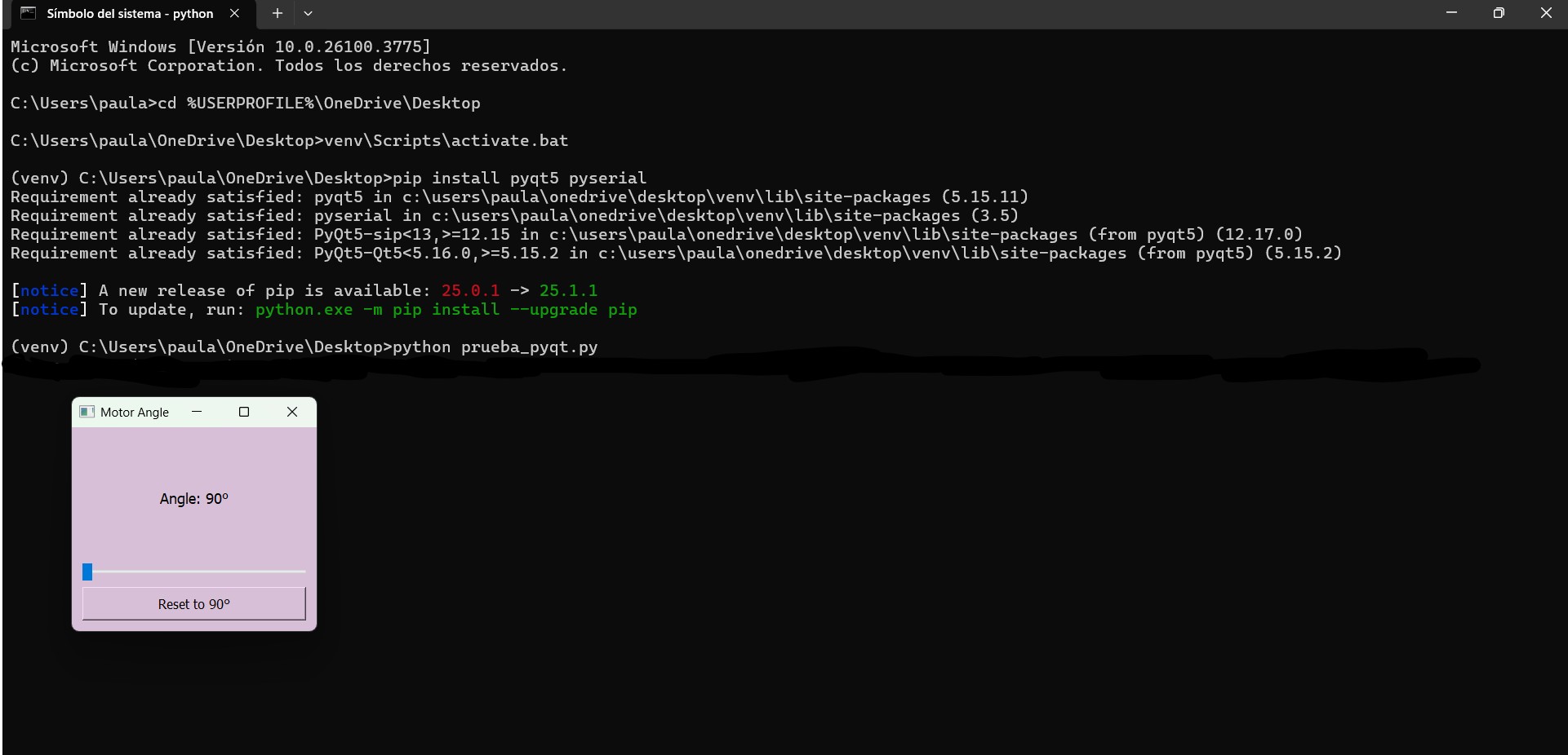
Steps in CMD:
- Create a virtual environment:
cd %USERPROFILE%\OneDrive\Desktop - Activate it:
venv\Scripts\activate.bat - Install necessary packages:
pip install pyqt5 pyserial - Run your script:
python NAME OF YOUR FILE.py
Arduino Code
This code listens for serial input and moves the servo accordingly. Works with both ESP32-C3 (115200 baud) and RP2040 (9600 baud).
#include <Servo.h>

Servo servoMotor;
const int servoPin = 0;  // Pin D0 en RP2040

void setup() {
  Serial.begin(9600); // Cambiar a 115200 si usas ESP32
  servoMotor.attach(servoPin);
  servoMotor.write(90);
}

void loop() {
  if (Serial.available()) {
    String input = Serial.readStringUntil('\n');
    int angle = input.toInt();
    if (angle >= 90 && angle <= 180) {
      servoMotor.write(angle);
    }
  }
}
Python PyQt Code
This interface lets me move the servo from 90° to 180°, useful for precise motion in my exoskeleton design.
from PyQt5.QtWidgets import QApplication, QWidget, QVBoxLayout, QLabel, QSlider, QPushButton
from PyQt5.QtCore import Qt
import serial

class MotorAngleWindow(QWidget):
    def __init__(self):
        super().__init__()
        self.setWindowTitle("Motor Angle")
        self.setGeometry(100, 100, 300, 250)
        self.setStyleSheet("background-color: #D8BFD8;")

        try:
            self.ser = serial.Serial('COM4', 9600)  # Cambia a 115200 si usas ESP32
        except serial.SerialException as e:
            self.ser = None
            print(f"Error abriendo el puerto serial: {e}")

        layout = QVBoxLayout()

        self.label = QLabel("Angle: 90°")
        self.label.setStyleSheet("font-size: 18px; color: black;")
        self.label.setAlignment(Qt.AlignCenter)
        layout.addWidget(self.label)

        self.slider = QSlider(Qt.Horizontal)
        self.slider.setMinimum(90)
        self.slider.setMaximum(180)
        self.slider.setValue(90)
        self.slider.valueChanged.connect(self.update_angle)
        layout.addWidget(self.slider)

        reset_button = QPushButton("Reset to 90°")
        reset_button.setStyleSheet("font-size: 16px; padding: 10px;")
        reset_button.clicked.connect(self.reset_angle)
        layout.addWidget(reset_button)

        self.setLayout(layout)

    def update_angle(self, value):
        self.label.setText(f"Angle: {value}°")
        self.send_angle(value)

    def reset_angle(self):
        self.slider.setValue(90)

    def send_angle(self, angle):
        if self.ser and self.ser.is_open:
            try:
                self.ser.write(f"{angle}\n".encode())
            except serial.SerialException as e:
                print(f"Error al enviar datos: {e}")

    def closeEvent(self, event):
        if self.ser and self.ser.is_open:
            self.ser.close()

app = QApplication([])
window = MotorAngleWindow()
window.show()
app.exec_()
Connection Diagram
- Servo signal → D0 (RP2040) or D3 (ESP32)
- All grounds connected together
Problems and Solutions
- PyQt5 window not displaying properly in VSCode:
I resolved this by running the script fromcmdinstead of the VSCode terminal, which prevented virtual environment or rendering conflicts. - Serial port opening error:
I ensured no other program was using the port and verified that the board was properly connected. - Baud rate mismatch:
I made sure the baud rate in the Arduino sketch matched the baud rate set in the Python code (either 9600 or 115200).
Final Result // Hero Shot
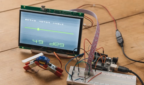
After uploading the Arduino code and running the PyQt app from CMD, I was able to move the servo smoothly from 90° to 180°. This allowed me to test fine movements, one degree at a time, which is exactly what I need for my exoskeleton joints.
Although I don’t have a battery yet, I tested everything using a power supply and it worked great.
Conclusion
This week was essential for understanding the link between GUI programming and embedded hardware. Using PyQt allowed me to make a user-friendly interface, while the serial communication handled
- © Copyright 2025 [Paula Rivero Robledo]
- Creative Commons Attribution Non Commercial