Molding and casting
Group Assignment - Week 13: Molding and Casting
During this week, as part of the group assignment, we focused on understanding and experimenting with different molding and casting materials. We started by reviewing the Safety Data Sheets (SDS) of each material to ensure safe handling during the process.
We then tested a variety of materials by performing several castings. This allowed us to observe and compare the curing times, flexibility, surface finish, and overall quality of the results.
Additionally, we compared molds created with 3D printing and CNC milling. Each method has its own advantages: 3D printing allowed for more complex geometries, while milled molds offered better surface finishes and precision in certain cases.
Overall, this assignment helped us gain practical knowledge about material behavior and the importance of choosing the right fabrication technique depending on the application.
You can see the full documentation of the group work here.
Summary
During this week, we learned how to design and fabricate molds using 3D modeling tools, prepare files for CNC machining, and use silicone rubber compounds to create flexible molds for casting. This process helps us understand how to replicate shapes accurately and produce multiple copies of a design.
Design in SolidWorks
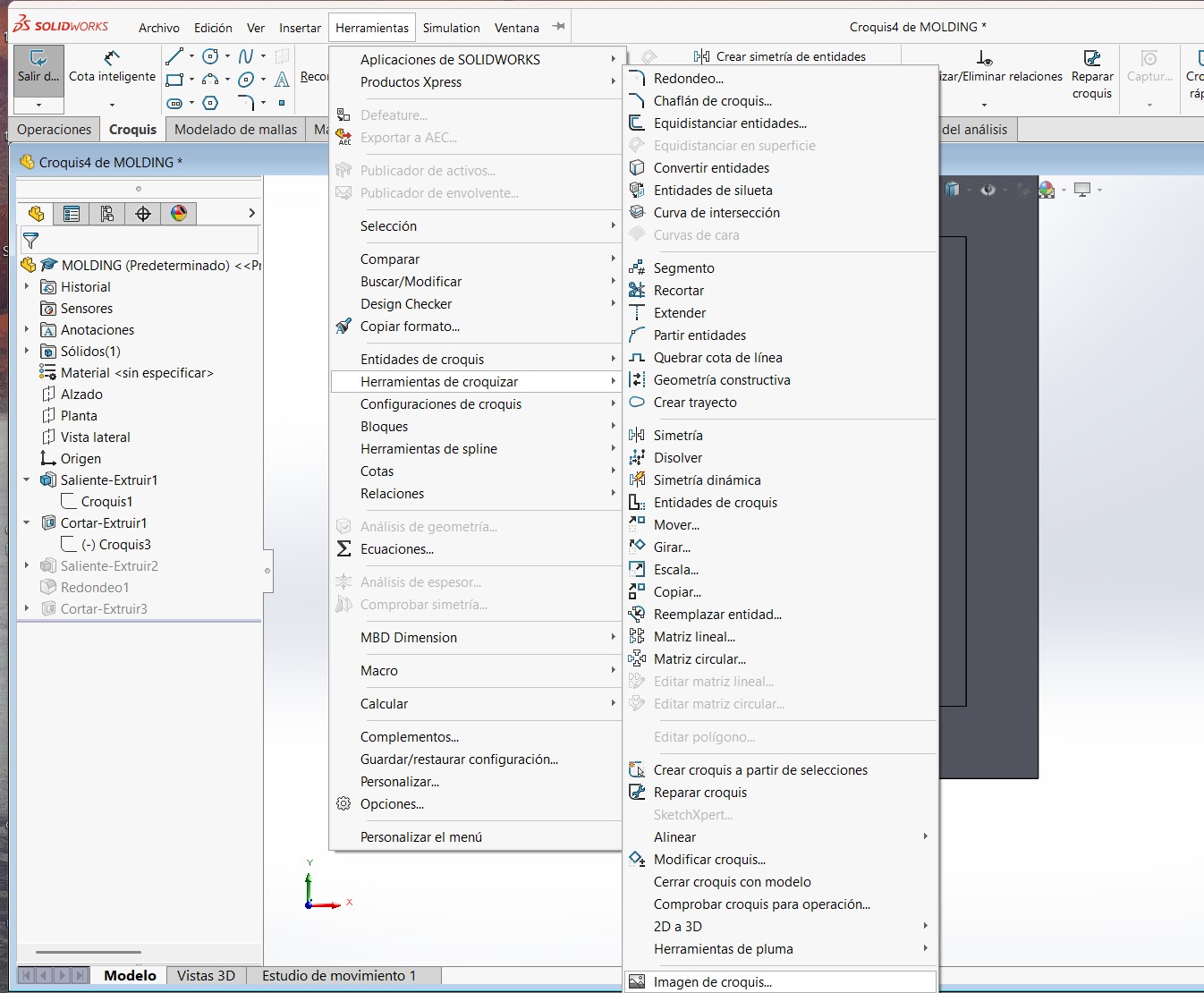
This time, I used an image as the base for my design. Here are the detailed steps I followed:
- Imported the reference image into SolidWorks.
- Opened a new sketch on the front plane and used the image as a background.
- Traced the outline of the shape using sketch tools like lines, arcs, and splines.
- Used the "Extruded Boss/Base" feature to create a 3D shape.
- Refined the dimensions and saved the model as an STL file for machining.
Design in SolidWorks
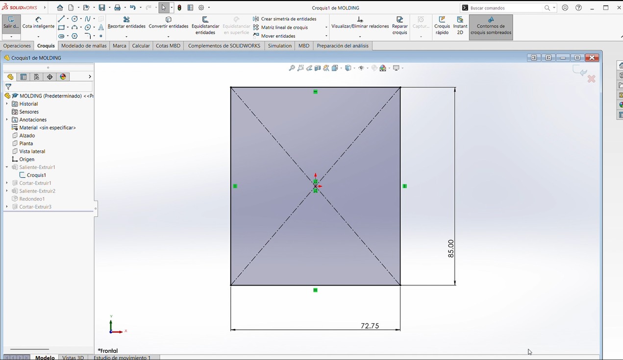
Step 1 – Create the Base Block
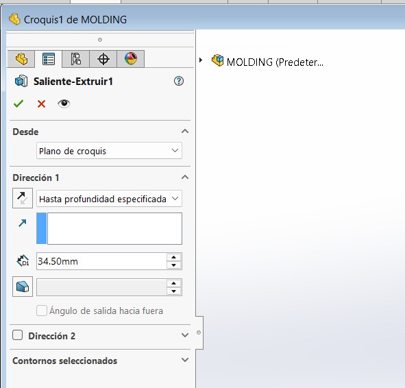
I started by sketching a rectangle with the same dimensions as my material: 72.75 mm x 85 mm. Then I used Extruded Boss/Base to give it a thickness of 34.50 mm, which matches the actual material thickness.
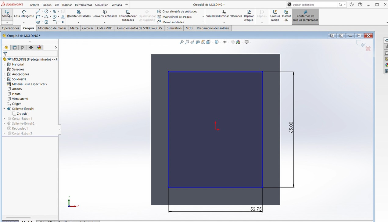
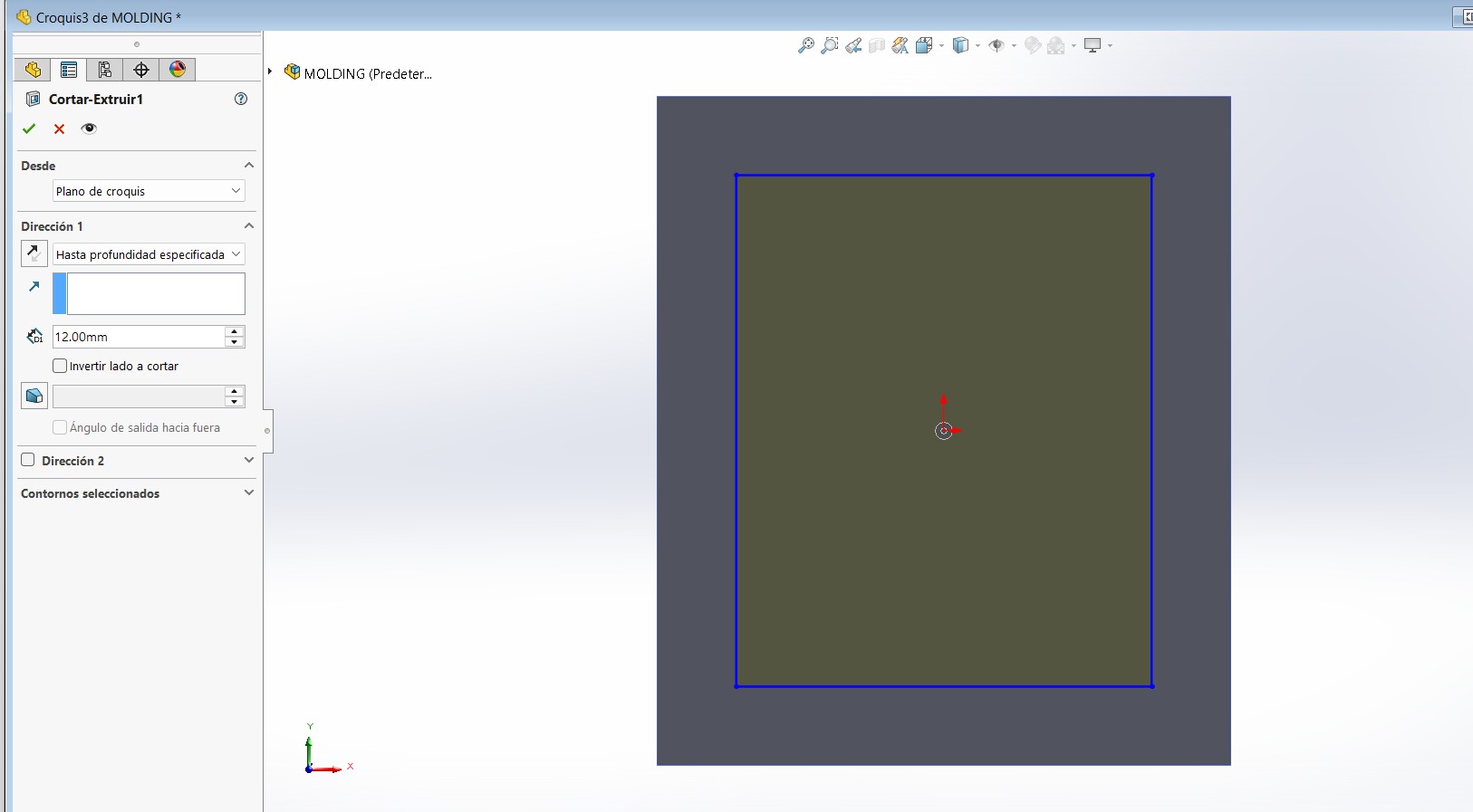
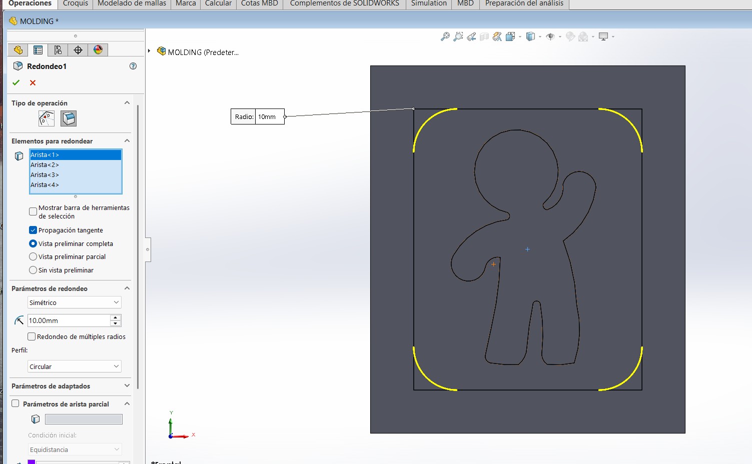
Step 2 – Cut the Mold Area
On the top face, I created another rectangle to define the cavity where my design will go. I used Extruded Cut with a depth of 12 mm, leaving 3 mm at the bottom.
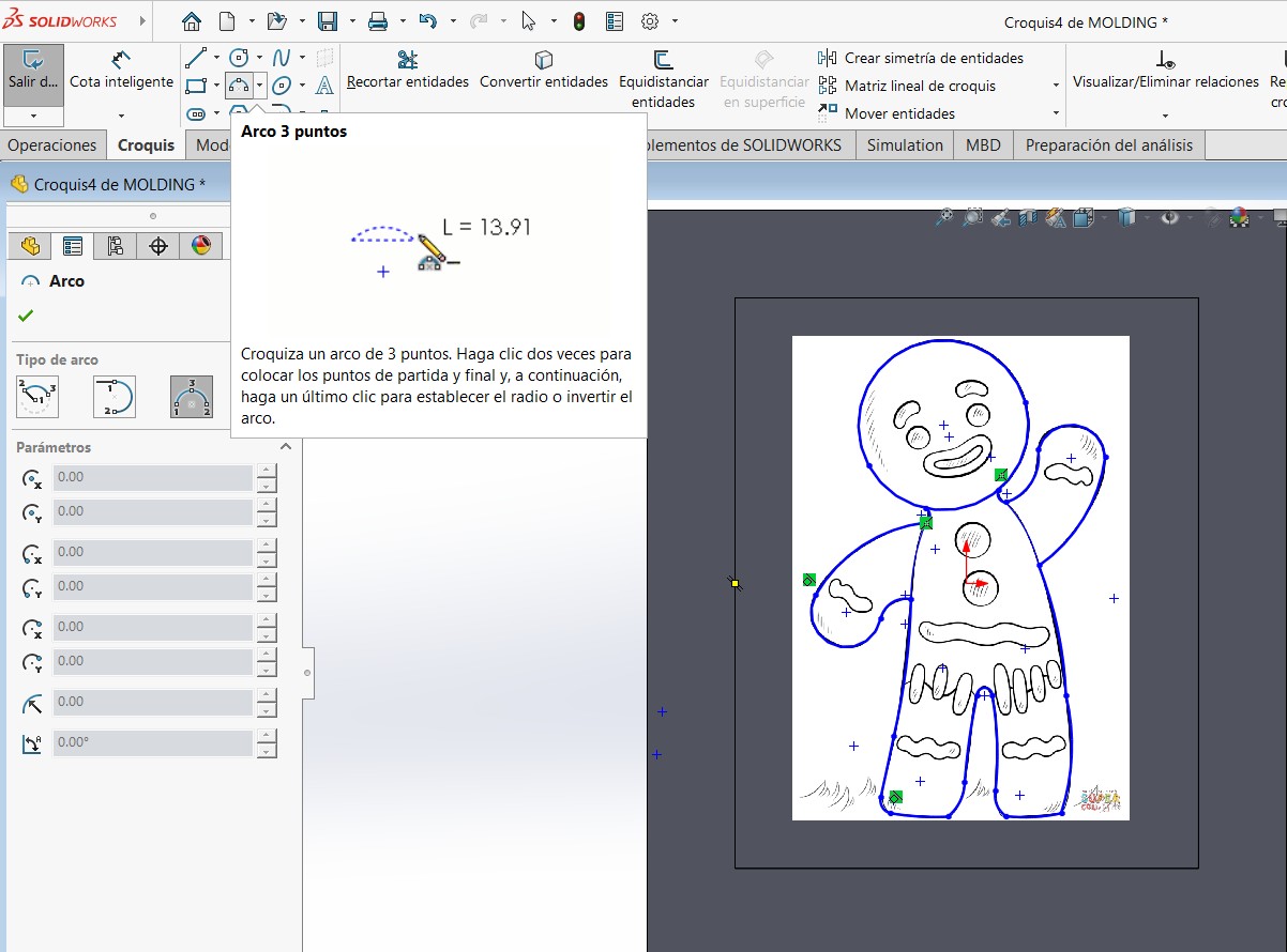
Step 3 – Import and Trace the Gingerbread Man
I inserted an image of a gingerbread man inside the cut area. Then, using 3-point arc and other sketch tools, I traced the contour of the figure.
Step 4 – Extrude the Main Shape
After finishing the sketch, I used Extruded Boss/Base again to give the gingerbread man shape a thickness of 10 mm.

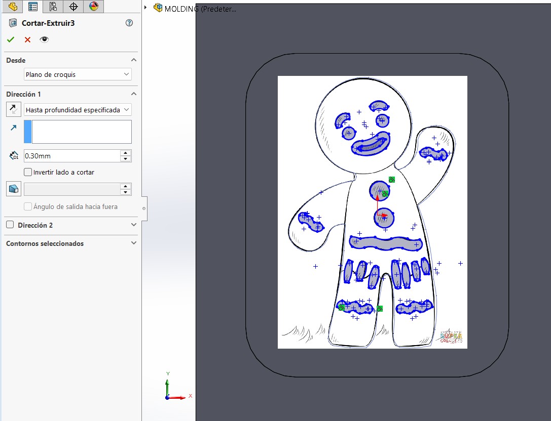
Step 5 – Add Details
I created another sketch on top of the gingerbread figure and added facial features and buttons. These details were cut-extruded to a depth of 3 mm into the shape.
Final Result
This completes the mold for the gingerbread man.And we saved it as an STL FILE.
Preparing the Toolpath in VCarve
The first task was to define the workspace dimensions in VCarve. I set it to 85 mm x 72.75 mm x 34.5 mm The model we are going to import, is our design in an STL file. After importing, I carefully aligned it in the workspace, making sure it was centered and fully positioned.
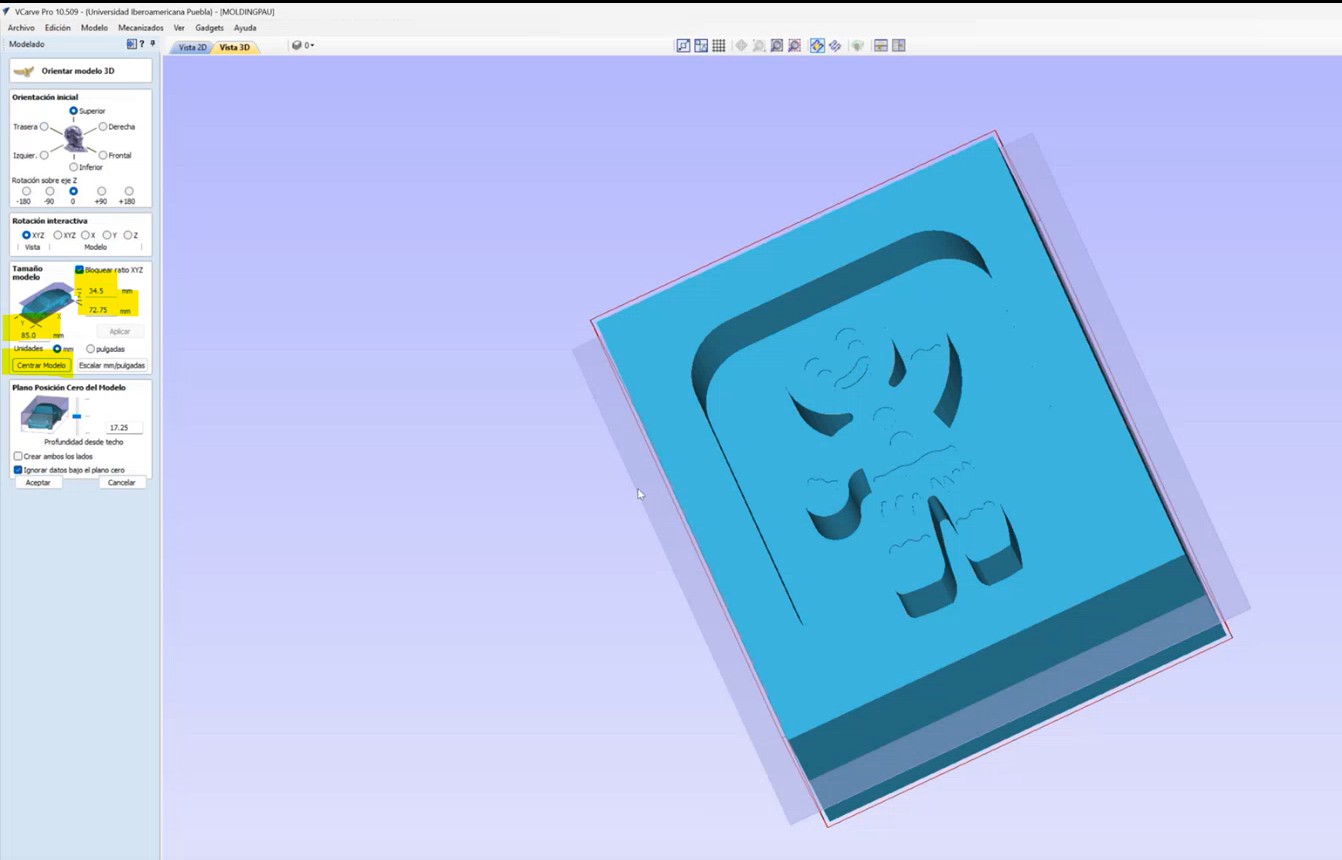
With the model ready, I began setting up the Roughing Toolpath using the options on the right panel.
Tool configuration was crucial. Our instructor provided two bits:
- 1/4" 2-flute straight flat endmill (25 mm flute) for roughing.
- 1/8" 4-flute upcut endmill (27 mm flute) for finishing.
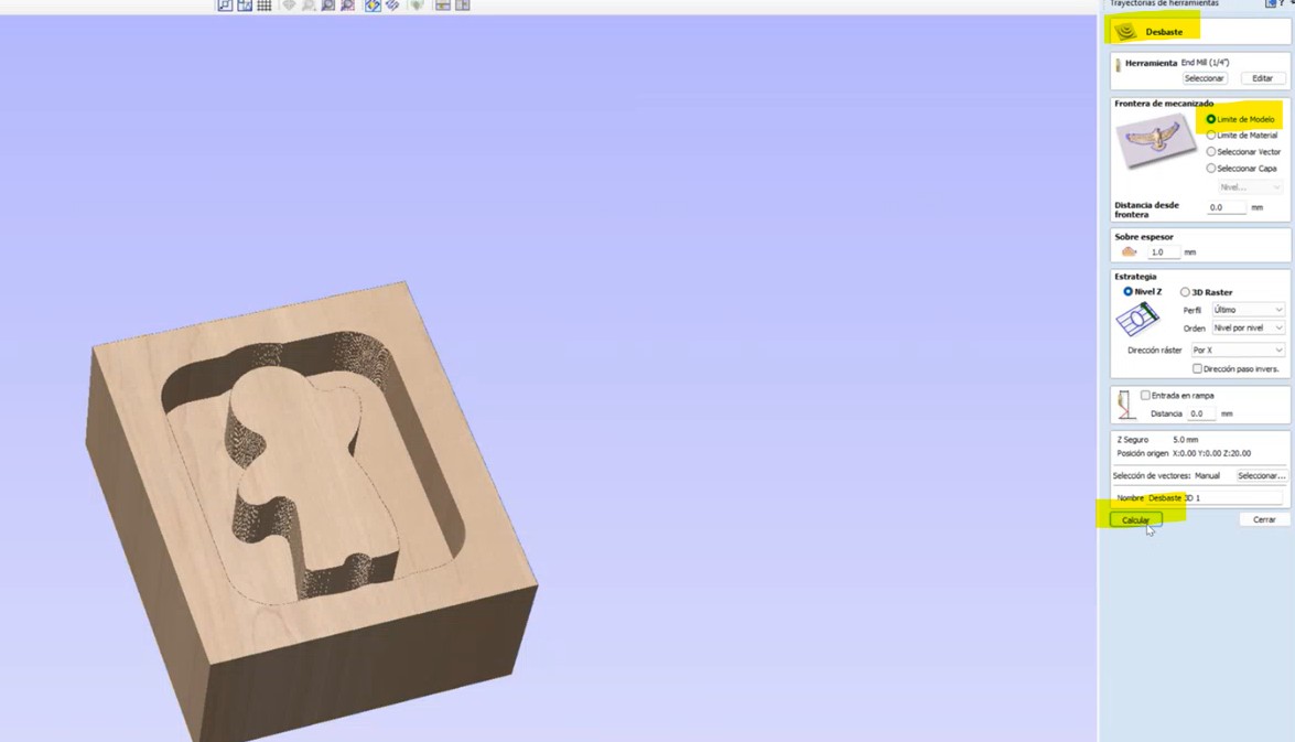
Since the the roughing is first, I set up the 1/4" tool with the following specs:
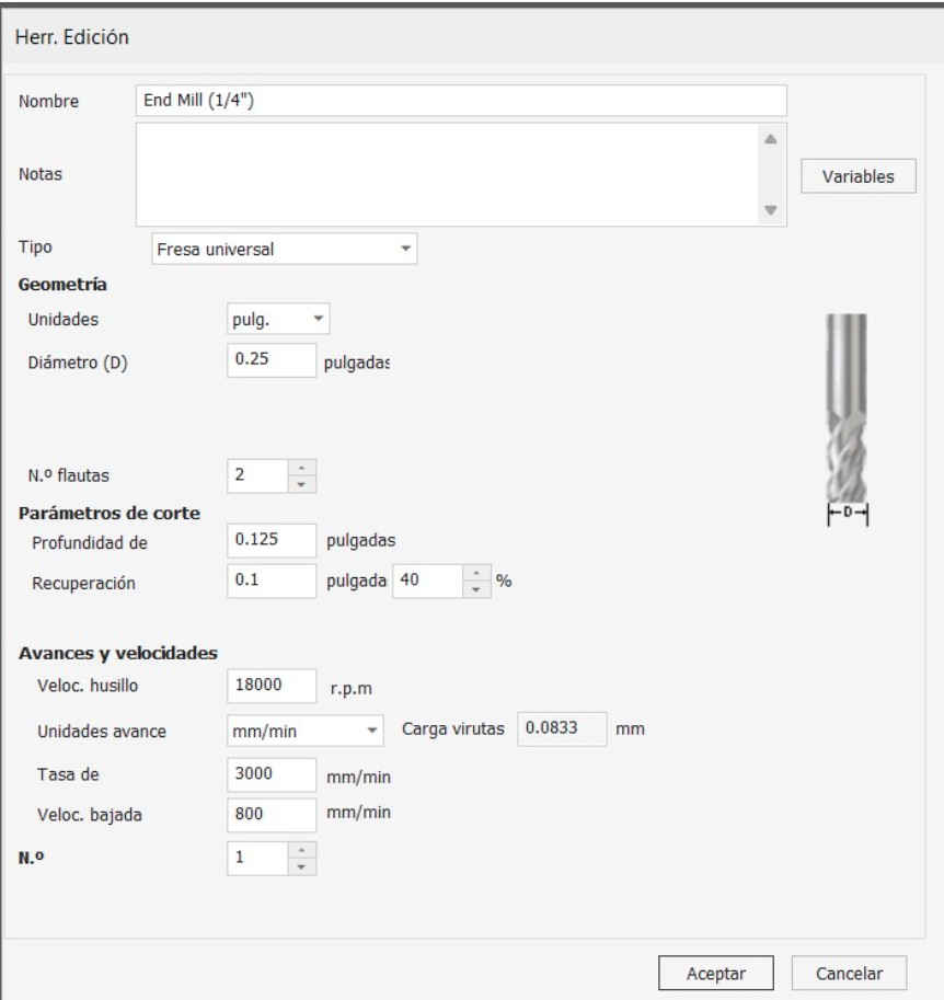
- Diameter: 0.25", Flutes: 2
- Depth per Pass: ~0.125" (50% of diameter)
- Stepover: 40% of the tool diameter
For speeds and feeds, I used:
- Spindle: 18,000 RPM
- Feed Rate: 3000 mm/min
- Plunge Rate: 800 mm/min
After completing the settings, I generated the roughing toolpath and ran a simulation to check for errors.
Next, I moved on to the Finishing Toolpath configuration.
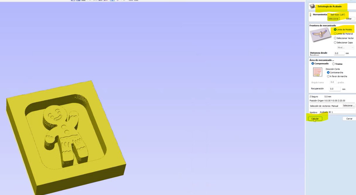
For the finishing toolpath I used the 1/8" 4-flute upcut endmill
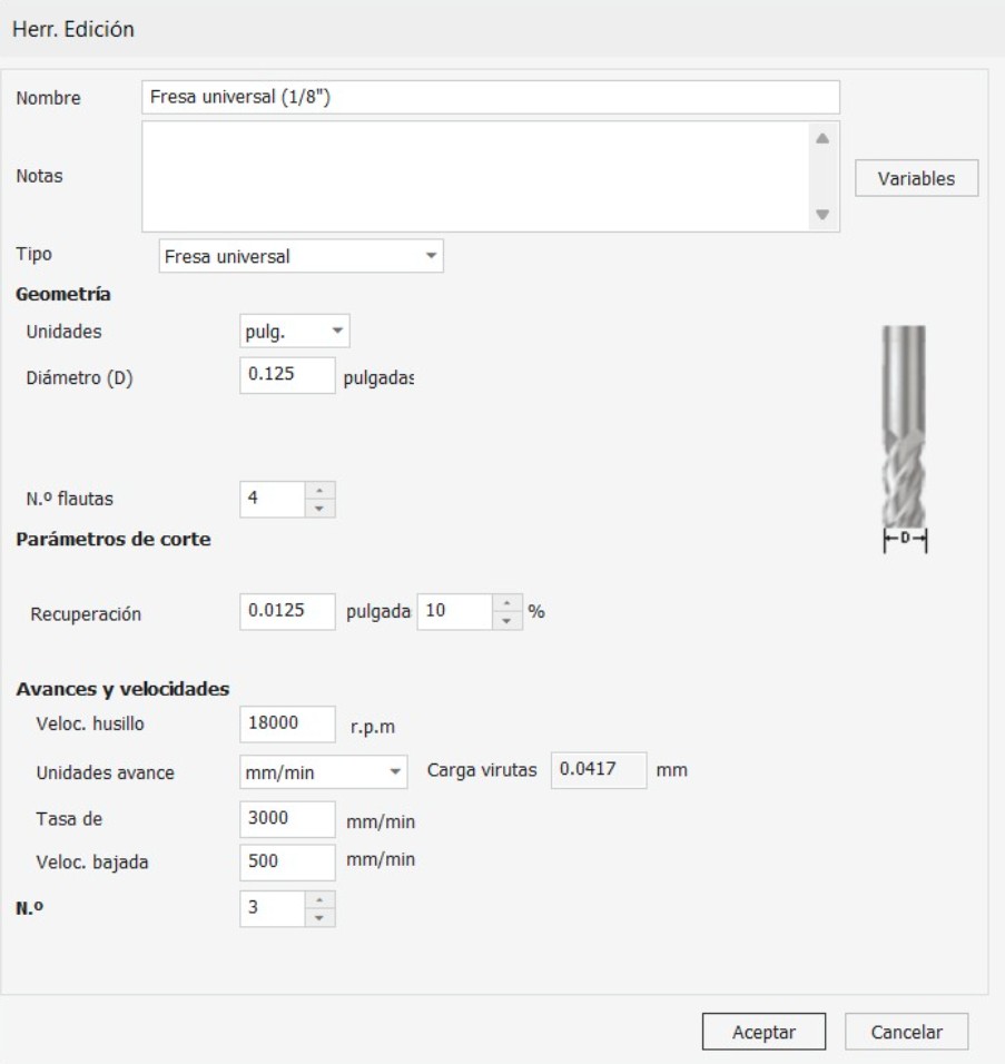
- Diameter: 0.125"
- Flutes: 4
- Stepdown: Minimal, auto-managed by software
- Stepover: 10% (very fine for high-quality finish)
- Spindle: 18,000 RPM
- Feed Rate: 3000 mm/min
- Plunge Rate: 500 mm/min
And then I simulated both the roughing and finishing toolpaths. The results confirmed proper tool movement.
Now that we run the simulation, and everything is find, I saved the project to a USB drive. I export the files using the AsiaRobotica-NK105.3-arcs (*.nc) post-processor.
NOTE: THE MATERIAL WAS TO LARGE FOR JUST MY PIECE, SO I SHARED THE WAX BLOCK WITH MY FABACADEMY PARTNER JOSE ÁNGEL ZÁRATE FERNÁNDEZ.Machining with the CNC Router
- Mounted the wax block securely on the CNC bed using double-sided tape to prevent any movement during machining.
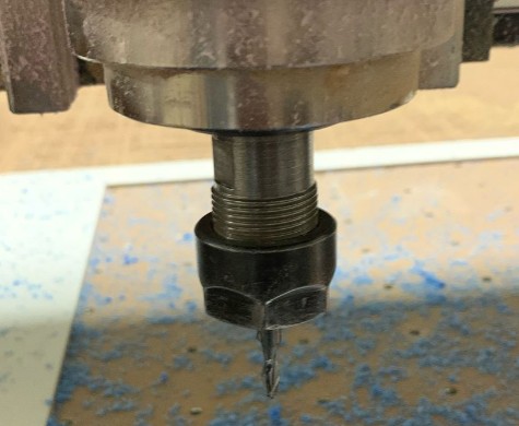
- Inserted the first tool, a 1/4" flat end mill, which performed the entire roughing process.
- To operate the machine, I followed the workflow described in more detail on the Week 7 page, where I explain how I used the Asia Robotic CNC.
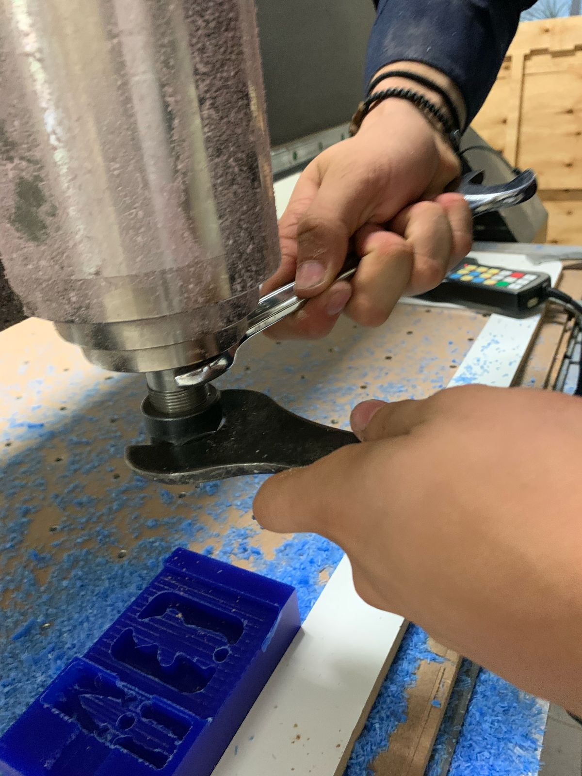
- Once the roughing was completed, I changed the tool to a 1/8" ball nose end mill for the finishing passes.
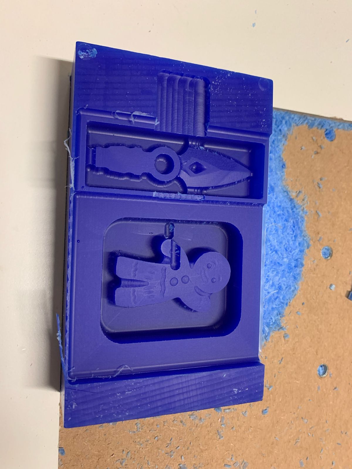
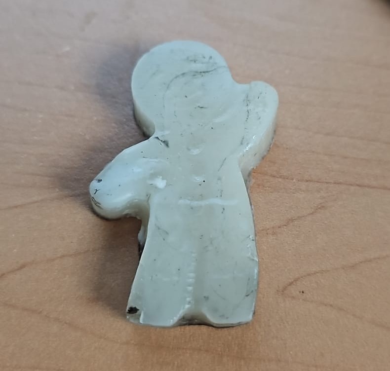
- Before starting the second cut, I forgot to re-zero the tool, which caused a small issue in the gingerbread man’s arm.
- After noticing the mistake, I re-set the zero point on the corner of the wax block, and the finishing pass completed without any further problems.
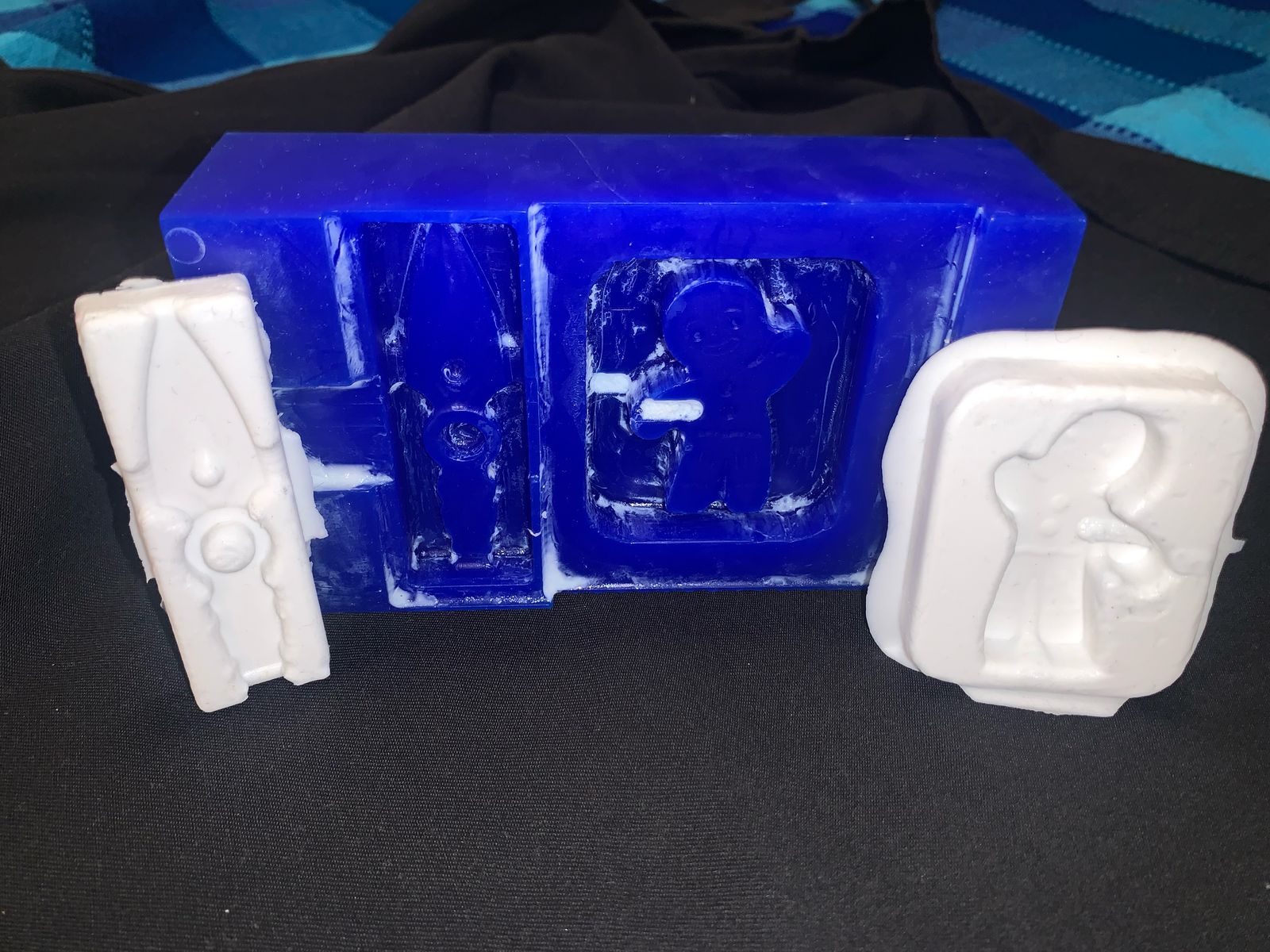
- This was the final result:
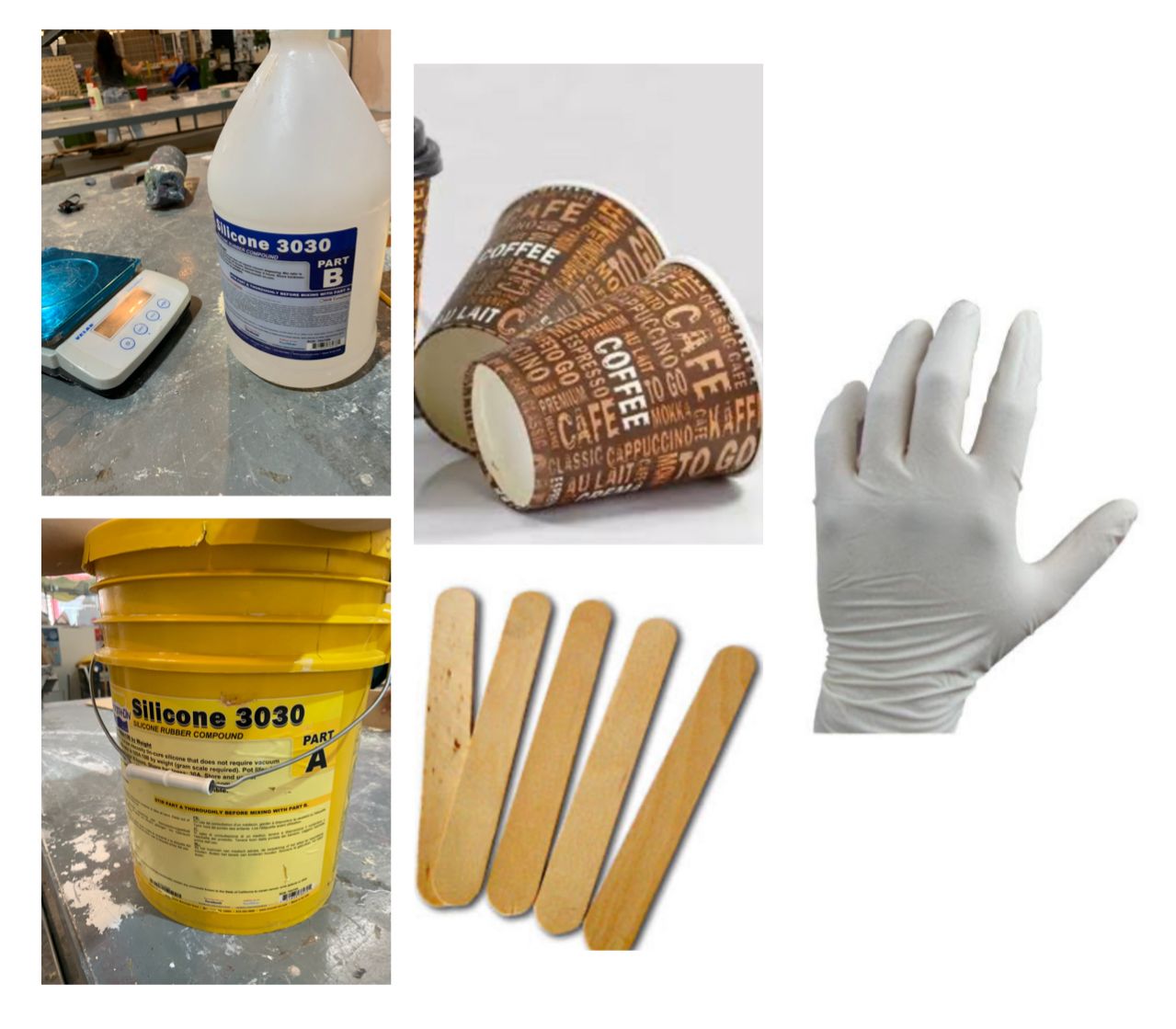
Materials for Silicone Mold Making
- Silicone 3030 Part A (Yellow bucket)
- Silicone 3030 Part B (White bottle)
- Digital scale
- Disposable coffee cups (used as containers)
- Wooden mixing sticks
- Nitrile or latex gloves
Mixing and Pouring the Silicone
Step-by-Step Calculation:
1. Base calculation for Part B (before adding the 10% increase):
The first step was to calculate the amount of Part B required based on a 10:1 ratio of Part A to Part B. I used the weight of **53.8 g** for Part A, so the required amount of Part B was:
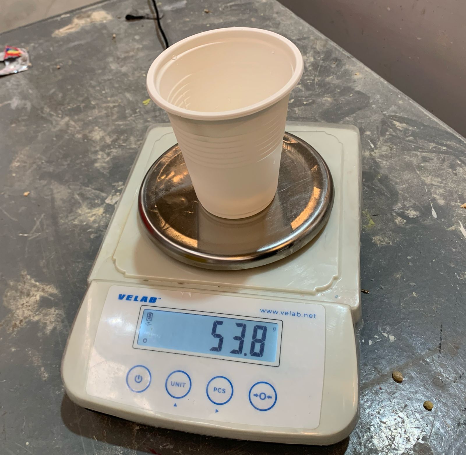
Part B = 53.8 g / 10 = 5.38 g
2.Adding 10% extra to Part B:
To ensure the proper curing and flexibility of the silicone, I decided to add 10% more to Part B. This increases the amount of Part B to:
Part B final = 5.38 g * 1.10 = 5.918 g
3. Total weight adjustment:
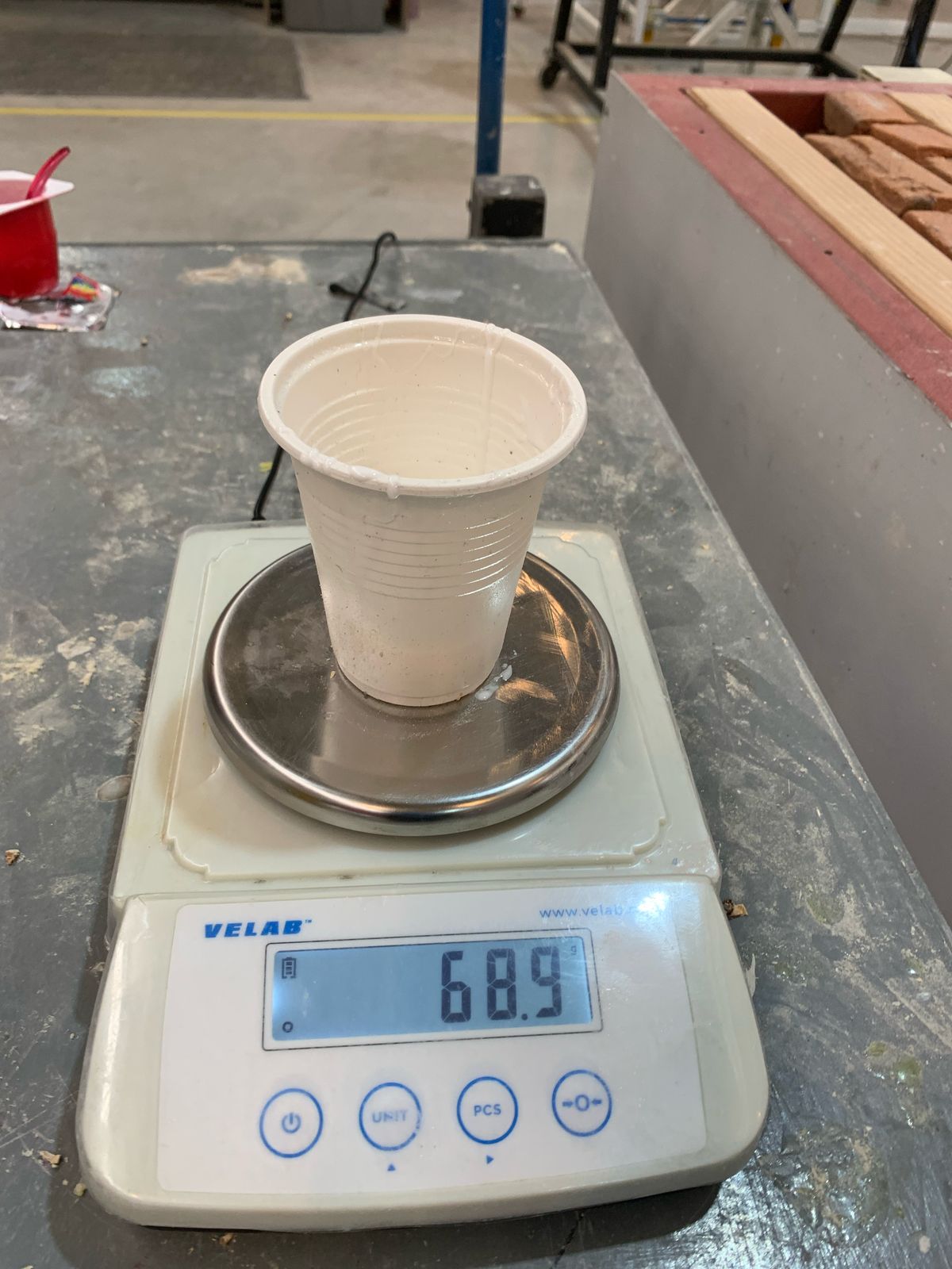
Adding the calculated amount of Part A (53.8 g) and Part B (5.918 g), the total weight of the silicone mixture before accounting for the container was:
Total adjusted weight = 53.8 g + 5.918 g = 59.718 g
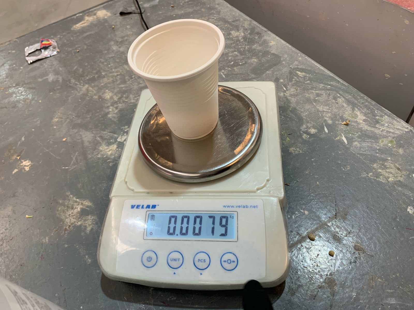
However, after considering the weight of the container (7.9 g), the final total weight I used for the mixture was 61 g.
Justification for Using More Part B:
I decided to use more Part B than originally calculated in order to modify the curing time and flexibility of the silicone. By increasing the amount of Part B, the curing process is accelerated, and the final mold becomes more rigid. This is especially useful when working with molds that need to set faster or require greater durability and detail retention.
In this case, the final weight of Part B used was 7.2 g, representing an increase of approximately 33.8% compared to the initial calculated amount (5.38 g). This modification ensures that the mold will cure more quickly and have the desired rigidity.
Mixing the Silicone:- Added Part B to Part A and mixed thoroughly.
- Poured the mixture into the wax mold slowly to avoid air bubbles.
- Tapped the mold to release air and let it cure for 16–24 hours.
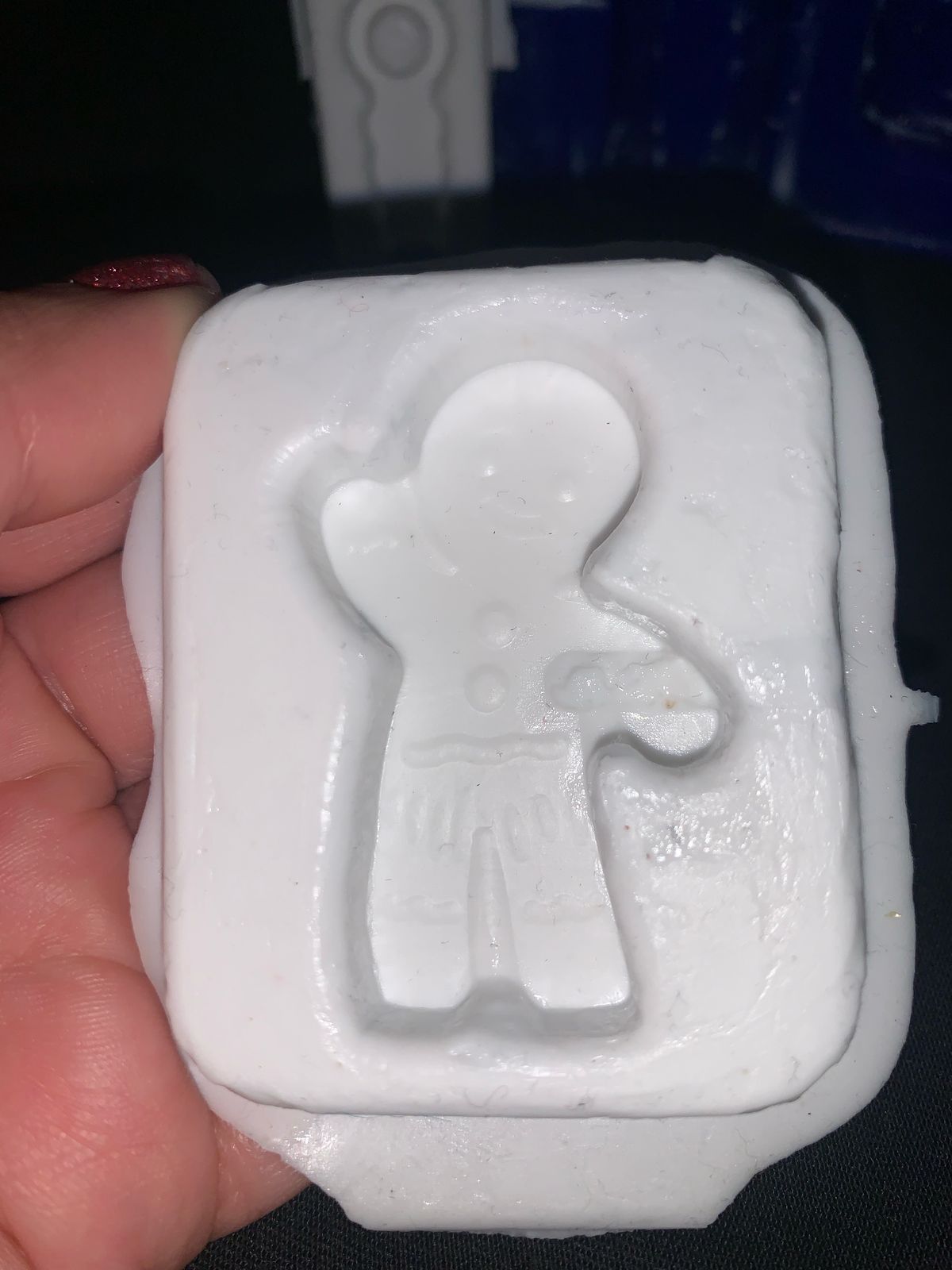
After curing, the silicone mold was flexible and detailed, ready for casting parts using resin or other materials.
Making the Wax Candle
After completing the silicone mold, I decided to use it to make a candle. I purchased wax blocks specifically for candle making, melted them carefully with a spoon and a lighter, and poured the liquid wax into the silicone mold.
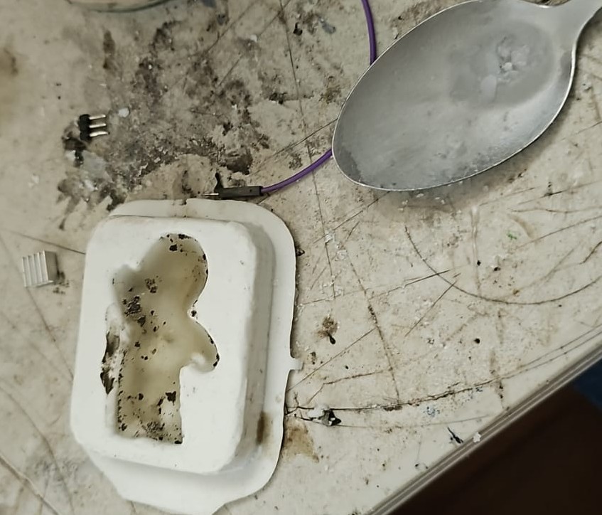
Wax Test Note: On my first try, I melted the wax directly using a spoon and a lighter. The wax turned black once cooled. This happened because the direct flame is very hot and oxygen-poor, which causes the wax to burn incompletely, producing soot through a process called pyrolysis.
I repeated the process, but this time used a double-boiler (a bowl over simmering water), which provides gentler and oxygen-rich heat. This method melted the wax cleanly. I poured the wax into the silicone mold and let it sit at room temperature until fully cooled and hardened (about 20–30 minutes).
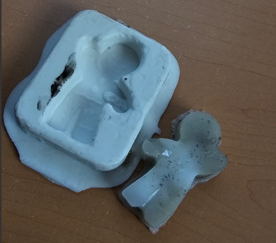
Once the wax had solidified, I carefully removed the candle by flexing the silicone mold and gently pressing from the bottom to avoid damage.
The result came out like this:
Learning Outcomes
- Understood how to design a positive 3D model for mold making using SolidWorks.
- Learned how to use VCarve to prepare roughing and finishing toolpaths for CNC machining.
- Gained hands-on experience operating the CNC router and troubleshooting machining issues.
- Explored the chemical mixing and curing process of silicone rubber for mold making.
- Practiced casting with wax and learned how to demold safely and cleanly.
Tips I Wish I Had Known Before
- Always zero the CNC tool again after changing bits to avoid depth errors.
- Use baby powder or mold release before pouring silicone to prevent sticking.
- Double-check the alignment and centering of your model in VCarve before generating toolpaths.
- Pour silicone slowly and from a height to reduce bubbles.
- Wear gloves and prepare all materials in advance—silicone sets faster than you think!
Things I Would Improve
- Add registration marks or keying features to the mold to align parts better when casting.
- Design the mold with a pouring channel and air vents for better casting results.
- Use a vacuum chamber for degassing silicone to eliminate bubbles completely.
- Test the toolpath simulation twice—once in VCarve and once mentally step-by-step before machining.
- Consider designing a two-part mold if the object has complex geometry or undercuts.
Documents