Computer controlled machining
Introduction
This week in Fab Academy, we explored Computer-Controlled Cutting, focusing on CNC machines to create precise and scalable designs. This digital fabrication process is crucial in modern manufacturing, allowing for efficient and accurate production of large-scale structures.
What is Computer-Controlled Cutting?
Computer-Controlled Cutting refers to the process of using a machine, such as a CNC (Computer Numerical Control) router or laser cutter, to cut, carve, or engrave materials with high precision. These machines follow digital design files to execute cuts, making them ideal for creating intricate patterns, precise components, and large structures. Unlike manual cutting tools, CNC machines operate automatically, reducing human error and increasing efficiency.
Machine Used
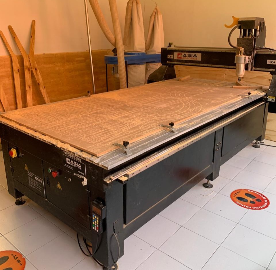
For this assignment, we used the Asia Robotica CNC Router Model 1325 Below are its specifications:
| Attribute | Details |
|---|---|
| Machine | Asia Robotica Shop-1325 |
| Dimensions | 3 x 1.8 x 1.7 meters |
| Motor Power | 4 HP at 24,000 RPM |
| Power Supply | 220V / 2F / 3.5KW |
| Material Fixtures | Clamps |
| More Info | Asia Robotica CNC Router |
Assignments
Group Assignment
During the group assignment, we gained hands-on experience in setting up and optimizing the CNC machine. Understanding how to test for runout, alignment, fixturing, speeds, feeds, materials, and toolpaths was crucial for ensuring precise and efficient cutting. This process highlighted the importance of machine calibration and the impact of different parameters on the final output.
One of the key takeaways was the significance of proper fixturing. Securing the material correctly prevents movement during cutting, ensuring accurate results and reducing the risk of errors. Additionally, adjusting speeds and feeds based on the material type improved the quality of the cuts and extended the lifespan of the cutting tools.
This assignment emphasized the necessity of teamwork and problem-solving, as each test provided insights that helped refine our approach. Overall, the experience reinforced the importance of preparation and fine-tuning settings before executing a full-scale project.
For more details, visit the Group Assignment Page.
Individual Assignment
For this individual assignment, I first thought about something I needed at home, and I realized that I lacked a shelf above my desk since I had no place to put my things.
I searched for inspiration on the internet by looking up “floating shelves” and found several designs that caught my attention, such as the following:


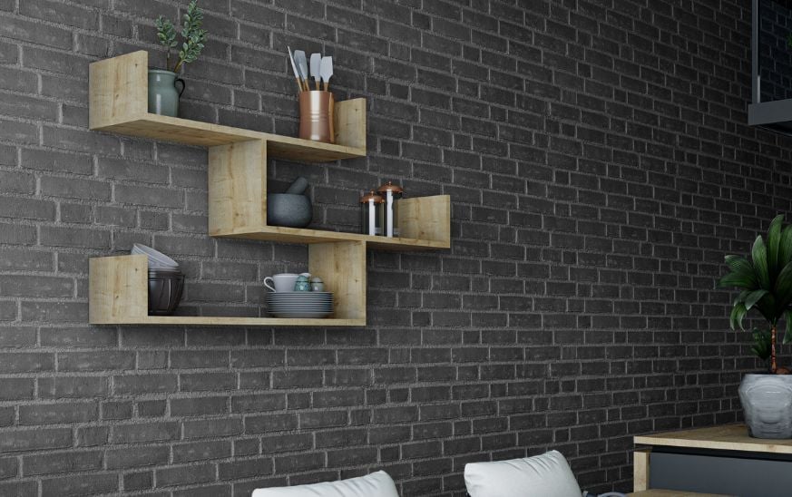
Once I found my inspiration, I decided to create design number 2, as I liked its complexity, the assembly, and how it would look in the designated space.
Shelf Design
For the shelf design, I used SolidWorks, which is a paid software. You can download it here.
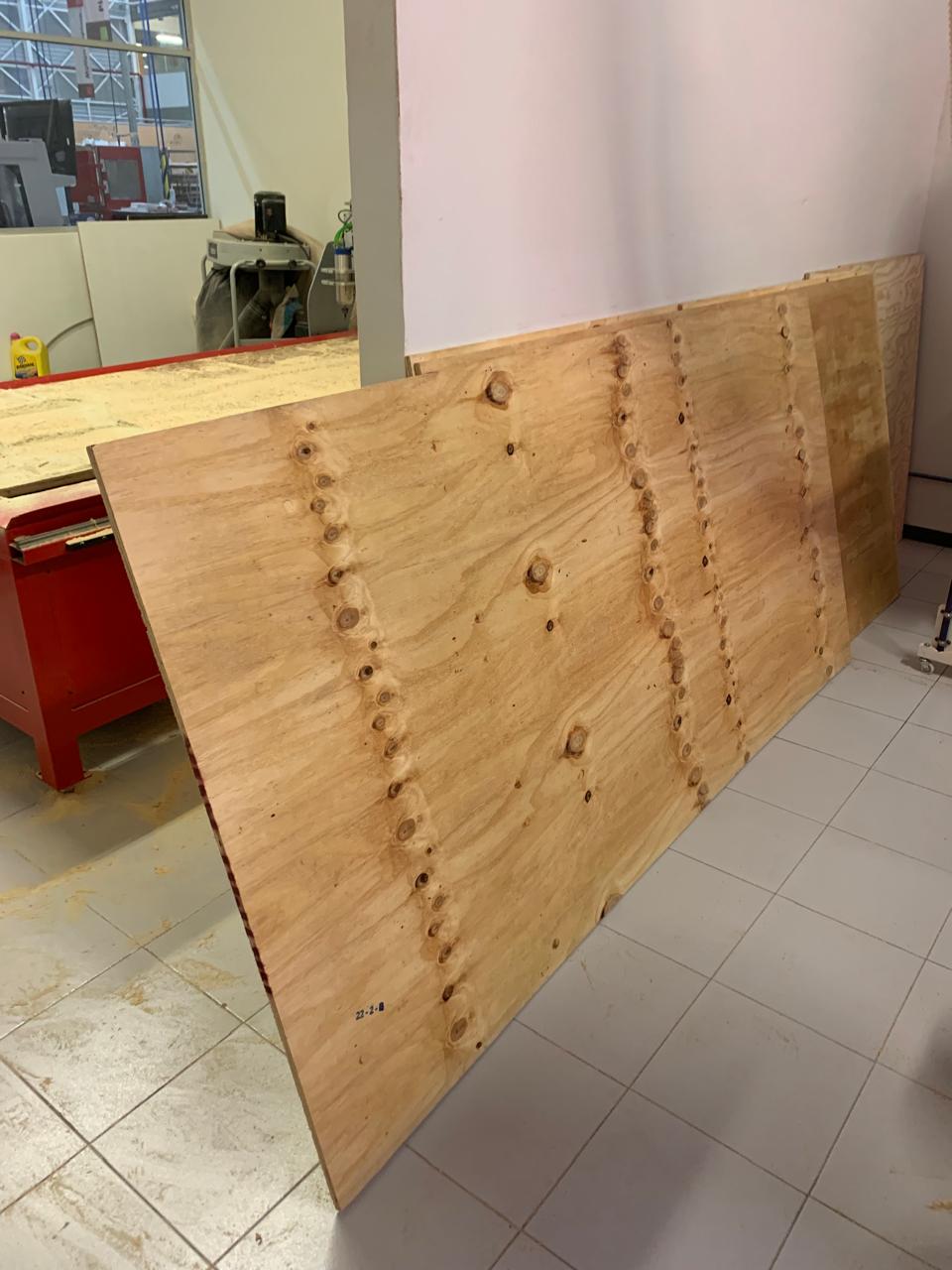
Since the design consists of rectangles and squares, there was no significant complexity in that part. The difficult part was determining the fitting measurements of the pieces, as they had to be symmetrical. I used 15mm thick wood.
Design Process
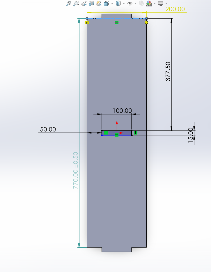
To begin, I drew two rectangles. I measured my wall and found that I could fit a shelf measuring 800mm x 770mm x 200mm. I created two rectangles for the outer frame: one of 800mm x 200mm and another of 770mm x 200mm. I added tabs to each so they would fit snugly and lock in place.
These tabs were centered, and I proceeded to create a hole in the middle of each, aligned and cut inward by 10mm, ensuring the pieces that would support the center square would fit properly.
Lateral view image & bottom view image
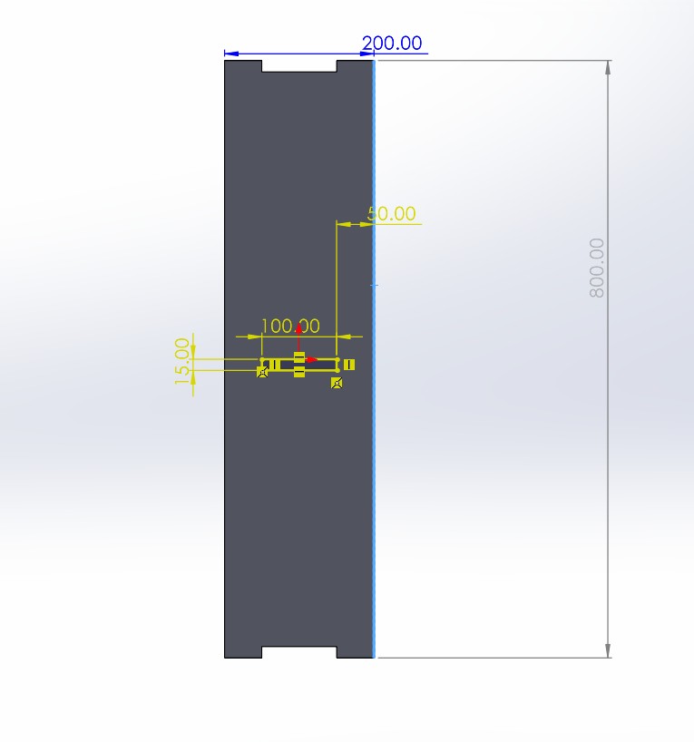
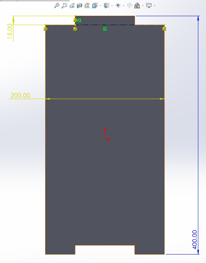
The shorter side and the top piece measured 385mm x 200mm. I designed them this way so they would be centered, and the tabs on the center square would fit adequately.
Side & top view image
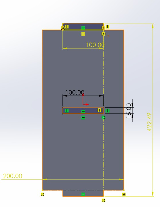
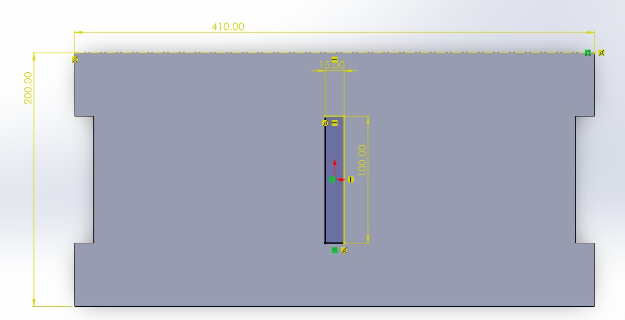
Once I had the outer frame, I proceeded to design the inner rectangle, which measured 410mm x 422.49mm. The two top pieces were identical, so I simply copied them, and the two side pieces were also identical. Both sets of pieces had tabs that interlocked, ensuring a tight fit with 15mm thickness (the material’s thickness).
Side inner rectangle image
Top inner rectangle image
Tip: Assemble the pieces as you finish them to verify that the measurements are correct.
Connecting the Inner and Outer Structures
Next, I created the pieces that connect the inner rectangle to the outer frame. While one might assume they should all be the same size, some required adjustments due to the alignment issues I encountered with the slots. The final dimensions were as follows:
Side Connectors
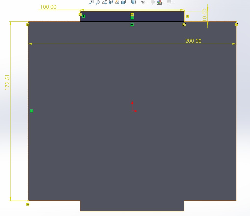
Top and Bottom Connectors
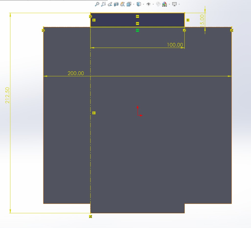
The Most Challenging Part: The Inner Slots
The most complicated part of the design was creating the four slots in the inner square. This was difficult because they needed to be perfectly aligned to ensure they fit properly when cut. I initially had alignment issues, but after adjusting the measurements, I resolved them, and the slots were correctly aligned and centered.
Final Assembly
Finally, I assembled all the pieces to verify that everything fit correctly. The assembly step is only for verification to ensure the structure is correctly aligned.
Preparing the File for CNC Cutting
Now that we have confirmed that all our pieces fit correctly, it’s time to prepare our file for the cutting machine. To do this, we save the SolidWorks files in .dxf format and proceed to create the CNC cutting program.
What is VCarve and How Does it Work?
VCarve is a computer-aided design (CAD) and computer-aided manufacturing (CAM) software that allows you to create files for CNC machines. It is perfect for designing and preparing files for 2D and 3D cutting, engraving, and modeling, using different materials. VCarve allows you to import various file types (such as DXF, SVG, and others) and convert those designs into precise instructions that the CNC machine can interpret.
How VCarve Works:
- Material Setup: First you need to define the material size. In this case, we are using a wooden board measuring 1200mm x 2400mm with a thickness of 15mm.
- Design: You can import design files from other CAD programs (like SolidWorks) or create your own designs within VCarve. In this case, we are importing our
.dxffiles from SolidWorks. It is important to import them one by one and arrange the pieces at your convenience. - Toolpath Generation: With the appropriate tools, you generate the cutting paths, which tell the CNC machine how to move the tool to cut the material.
- Simulation: VCarve allows you to simulate the cutting process to ensure everything looks good before starting the real job.
- Setup Simulation Environment: Once the toolpaths are generated, you can set up the simulation environment by selecting the material dimensions and tool used. This will allow you to simulate the cutting process in the context of the material's thickness and size.
- Run the Simulation: You can run the simulation to visualize the cutting paths. VCarve will show how the tool will move during the cutting process, allowing you to identify any mistakes, such as incorrect toolpaths or unexpected movements.
- Check for Errors: During the simulation, check for any areas where the tool might collide with the material, cut too deep, or miss sections of the design. If any issues arise, adjust the toolpaths or material setup before proceeding to the actual cutting.
- Final Verification: Once the simulation shows that the cutting paths are correct, you can finalize the settings and prepare the file for export to the CNC machine.
- Export: The final file is exported in a format compatible with the CNC, typically G-code (.tap or .nc).
In this video, we define the material dimensions in VCarve to match the actual wooden board. This step ensures that all toolpaths are scaled correctly, preventing cutting errors.
This video shows how the design is imported into VCarve. Arranging the parts efficiently maximizes material usage and ensures proper positioning before generating the toolpaths.
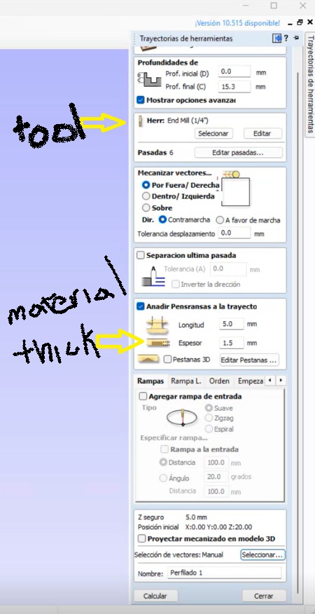
Here, different toolpath settings are configured in VCarve, specifying the cutting depth, tool diameter, and cutting order. Proper toolpath setup ensures a smooth and efficient cutting process.
Before starting the actual cutting process, it is essential to simulate the toolpath to ensure everything is correct. VCarve provides a powerful simulation feature that helps verify the cutting process and check for any potential errors before executing it on the machine. Here’s how to perform the simulation:
Steps for Simulation in VCarve:
This video demonstrates the simulation of the cutting paths in VCarve. By previewing the tool movement, we can detect potential errors and adjust the design before actual cutting.
The simulation is an essential step to minimize errors and ensure that the cutting process will be executed smoothly. It's crucial to double-check toolpath alignment and ensure the material is properly set up before starting the actual cutting process.
Download VCarve
You can find more information and download the software from the official website at the following link:
VCarve - Official Download PageCutting on the CNC
Before cutting on the CNC, it is important to wear safety equipment, including gloves, safety glasses, and a lab coat. It is also recommended to use headphones to reduce noise exposure. A crucial rule is to never leave the CNC unattended while it is running.
Preparing the Material
Place your material on the CNC table and secure it with clamps, ensuring that the cutting tool will not pass through them.


Design – Tolerances and CNC Design Choices
When designing the shelf, I used a 0.2 mm tolerance to ensure a proper fit between parts. This allowed for a snug connection without needing additional force or tools. I also added dog bone fillets in the internal corners to compensate for the round shape left by the end mill and allow tight-fitting joints.
CAM – Tool, Feeds, and Speeds
For the machining process, I used the following parameters:
- Tool: 1/4" flat end mill
- Spindle speed: 18,000 RPM
- Cutting feed rate: 1,200 mm/min
- Plunge rate: 300 mm/min
- Depth per pass: 3 mm
- Clearance height: 5 mm
These settings were chosen based on the material (15 mm wood).
Starting the CNC Machine
Turn on the machine, release the emergency stop button, and press the green start button.

Loading the File
Insert the USB drive, navigate to your file on the machine's control panel, and select "Copy Code" and "Play." This will load the program.

Setting the Origin
Adjust the machine’s origin to the bottom-left corner of the material. Be careful to avoid damaging the cutting tool.

Cutting Process
Once everything is set—origin adjusted, material secured, and program loaded—press "Play," and the machine will begin cutting.
Issue During Cutting
During the cutting process, the safety alarm went off, and I had to stop the machine. Unfortunately, I was unable to continue cutting that day. The next day, my teammate José Ángel from Fab Puebla and I managed to repair the machine. The issue was with the coolant system—it had run out of water, and one of the hoses was clogged.
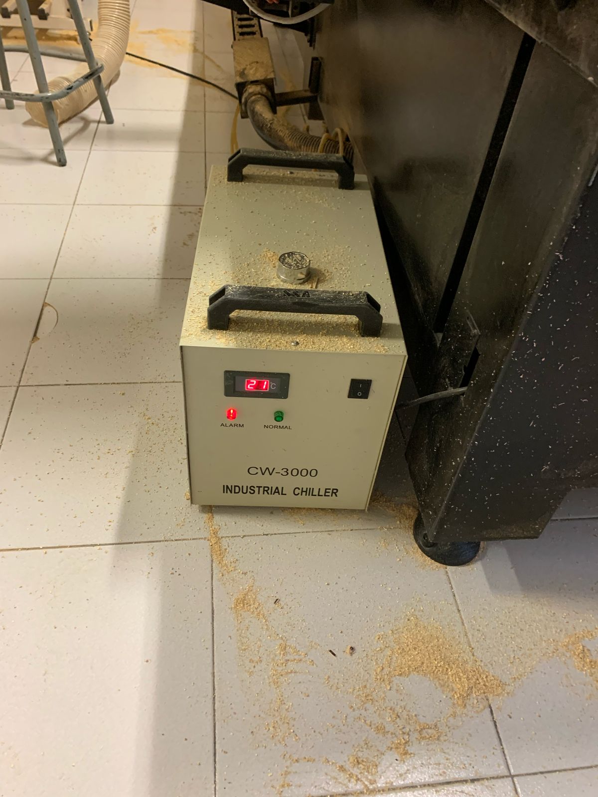
We refilled the coolant tank, removed air from the hoses, and repositioned them. The machine started working again. However, when I tried to cut the remaining pieces, the cutter did not lift properly, and it accidentally cut off a small section of the material. Fortunately, it was not a serious issue.

Post-Cutting Steps
After cutting, lift the cutting tool, turn off the machine, and remove your material.

Sanding and Assembling
For finishing, sand the edges and surfaces manually or with a sanding machine.


Once sanded, it's time to assemble.
Final Product
Once assembled, the piece should fit perfectly.

Optional: Painting
I used a two-in-one primer and paint spray for a better finish.


Conclusion
This week was a great learning experience. I not only improved my CNC cutting skills but also learned how to troubleshoot and repair machine issues. Encountering the problem with the coolant system and successfully fixing it with my teammate José Ángel was a valuable experience in problem-solving and teamwork. Despite the minor accident during the second round of cutting, the final product turned out well. This process reinforced the importance of careful planning, machine maintenance, and adaptability when unexpected issues arise.
