Input Devices
This week focuses on understanding and working with input devices. The objective is to measure signals from sensors and integrate them with a microcontroller board.
Group Assignment
This week, we focused on testing an analog and a digital input using two biomedical devices. For the analog input, we used the Sparkfun AD8232 Heart Rate Monitor, which required wiring to an oscilloscope to measure the heart signal. The sensor was placed on a person’s body following the Einthoven triangle for heart rate monitoring, and we observed the signal on the oscilloscope, which appeared as a noisy version of the expected pattern.
For the digital input, we used the MAX30102 Blood Oxygen Sensor, which communicates via I2C protocol. We connected the sensor to a microcontroller and uploaded a code to read heart rate and oxygen saturation (SPO2) values. The data was then sent to the serial monitor for analysis, where we observed the clock and data signals on an oscilloscope. The week’s activity helped us explore the wiring, signal reading, and data interpretation for both types of inputs in biomedical applications.
If you want to learn more about the group assignment, visit the following link: Group Assignment - Fab Academy 2025
Individual Assignment
- Measure something: add a sensor to a microcontroller board that you have designed and read it.
Understanding Input Devices
Input devices are electronic components that capture data from the environment and convert it into electrical signals that can be processed by a microcontroller. These devices include sensors such as temperature sensors, light sensors, and motion sensors.
Choosing a Sensor
Before selecting the sensor for my project, I decided to compare some of the available sensors in our laboratory. During my research, I found two potential options: the KY-013 and the LM35. To better understand their operation, I reviewed their datasheets and highlighted key characteristics that differentiate them.
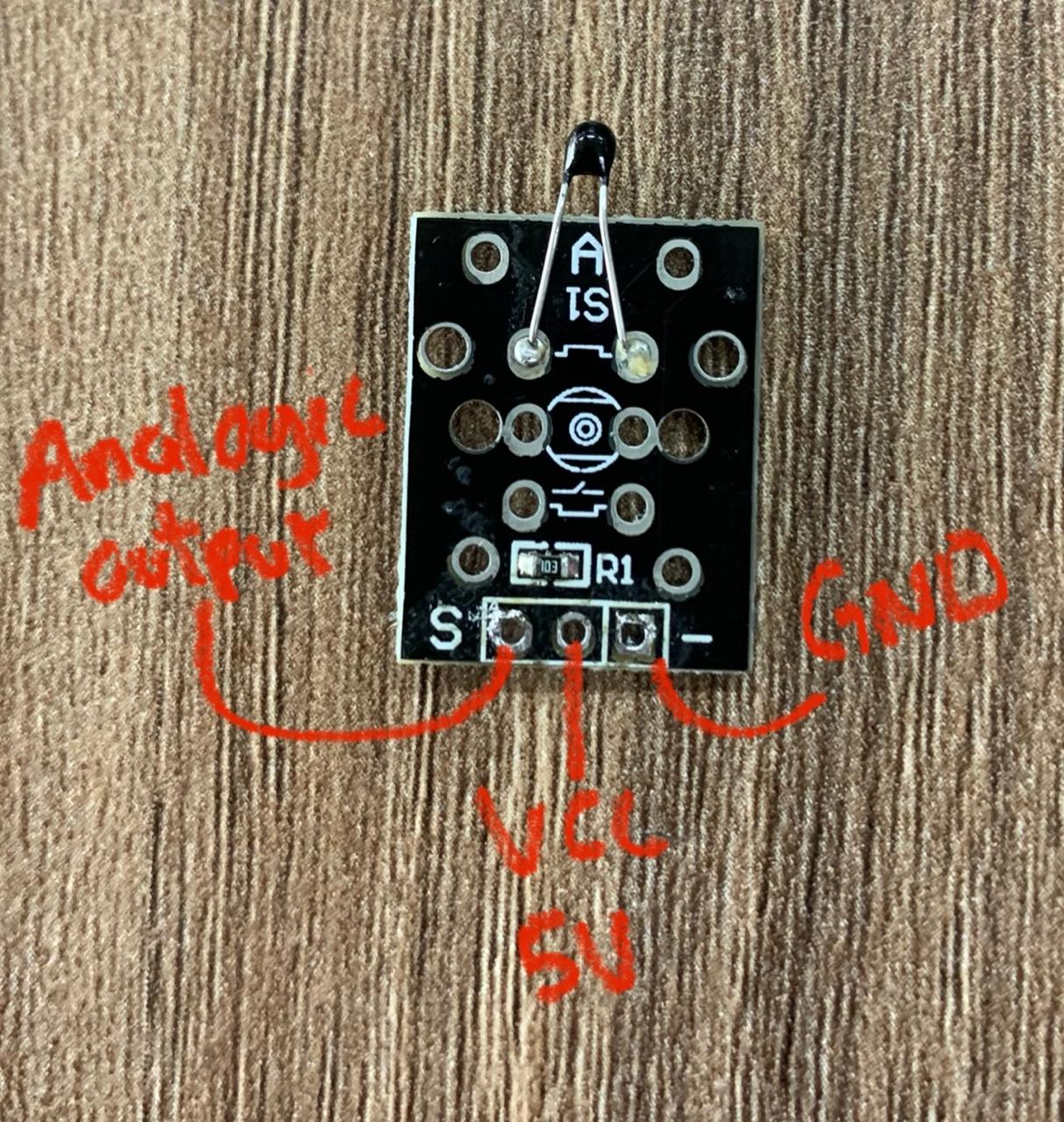
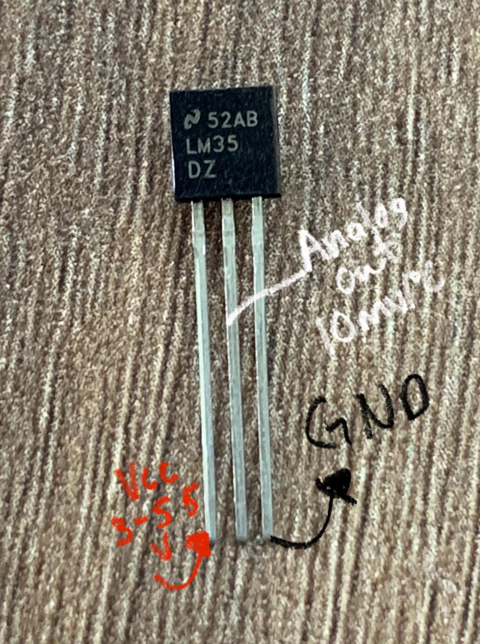
Sensor Comparison: KY-013 vs LM35
1. Sensor Overview
The KY-013 is a low-cost analog temperature sensor that provides a voltage output corresponding to the temperature. It operates over a wider temperature range compared to the LM35 but with lower accuracy.
The LM35 is a precision analog temperature sensor that provides an output voltage proportional to the centigrade temperature. It is known for its high accuracy and is commonly used for temperature measurements in biomedical and environmental systems.
2. Features Comparison
| Feature | KY-013 | LM35 |
|---|---|---|
| Output Type | Analog Voltage | Analog Voltage |
| Voltage Range | 0-5V | 0-5V |
| Accuracy | ±2°C (typical) | ±0.5°C |
| Operating Temperature | -40°C to 125°C | -55°C to 150°C |
| Power Supply | 5V | 5V |
| Output Voltage at 0°C | Approx. 1.5V | 0.5V |
| Applications | Basic temperature measurements in low-cost projects | Precision temperature measurement in various applications (environmental monitoring, biomedical, etc.) |
3. Why I Chose the LM35
After evaluating both sensors, I decided to use the LM35 for my project because it offers much higher precision, which is crucial when monitoring human body temperature. While the KY-013 typically has an accuracy of ±2°C, the LM35 provides a much more precise accuracy of ±0.5°C. This level of precision is essential for healthcare applications or wearable devices where even small temperature variations can be significant.
The LM35's output is directly proportional to the temperature in Celsius, making it easier to convert the analog output into meaningful temperature data. Since the LM35 is more reliable and accurate, it ensures that the readings are consistent, making it ideal for tasks such as health monitoring systems that require precise body temperature measurements.
Using My Custom PCB from Week 8
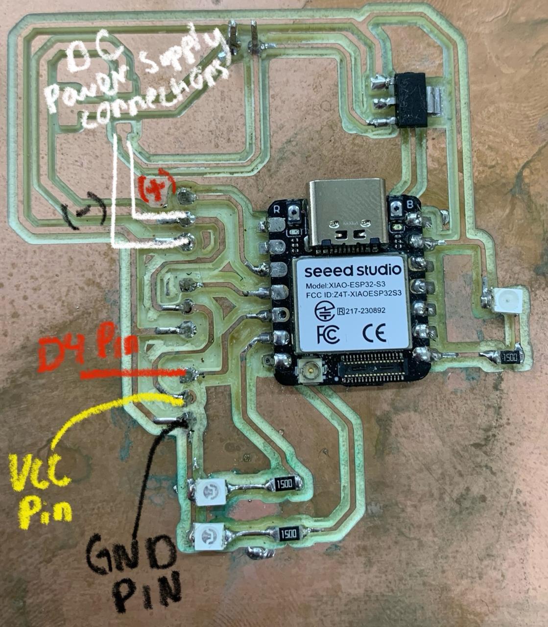
For this project, I used the custom PCB that I designed and fabricated during Week 8 of the Fab Academy, as part of the Electronics Production assignment. You can find more details about its development here.
- Microcontroller: Xiao, which operates at 3.3V and includes its own voltage regulator.
- Sensor Connection: The LM35 temperature sensor is connected to an analog pin for data acquisition.
- Power Distribution: The board requires both 5V and 3.3V to function correctly.
I connected the components in the following way:
Power Supply Considerations
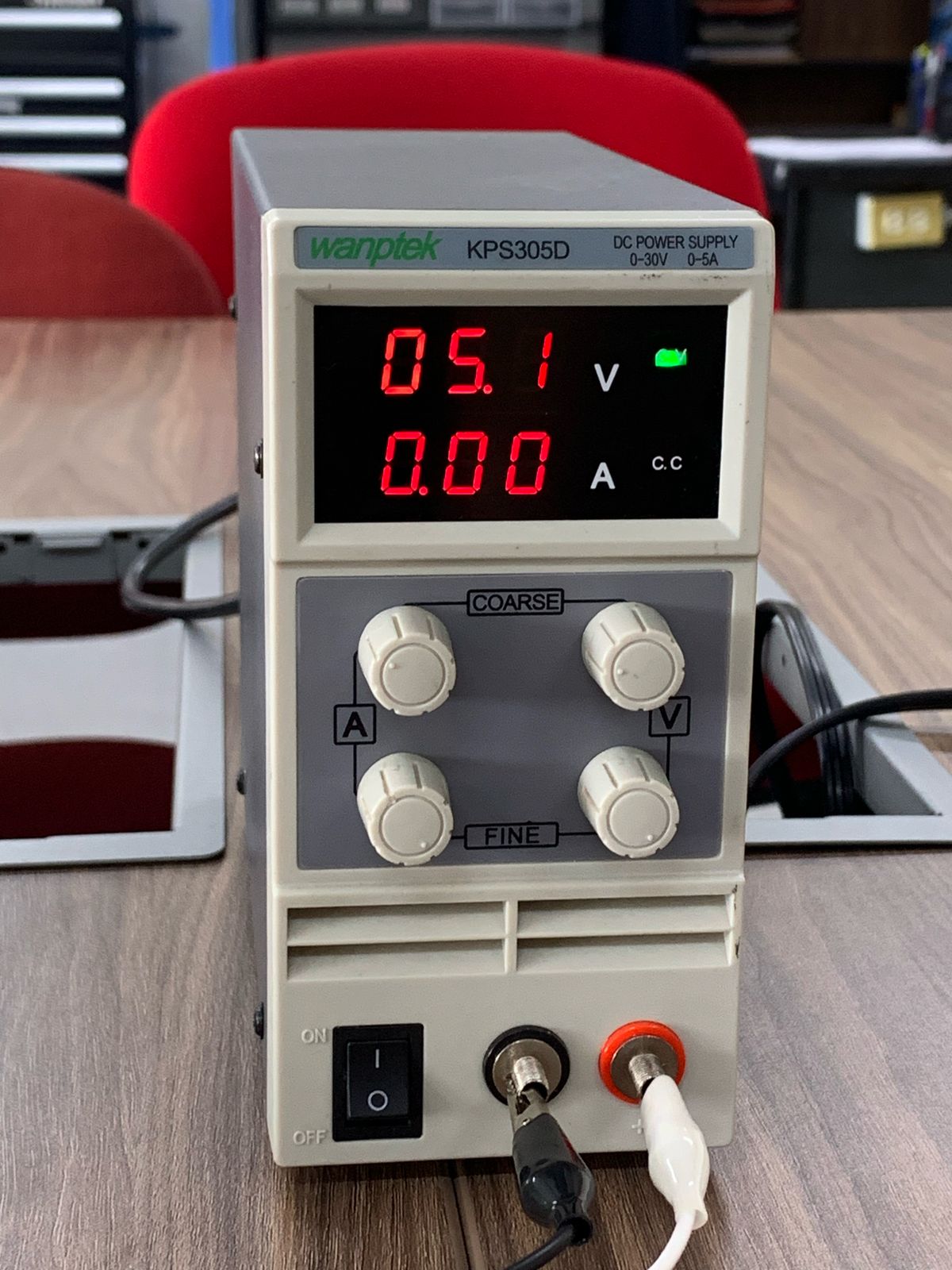
Currently, I still need to add a 5V voltage regulator to properly power the board from a battery. However, for now, I am using a DC power supply set to 5V to provide power to this part of the circuit.
Since the Xiao microcontroller has its own 3.3V regulator, I am powering it directly from my computer via USB, while the rest of the circuit operates at 5V. Once I integrate the voltage regulator, I will be able to power the entire system from a standalone battery.
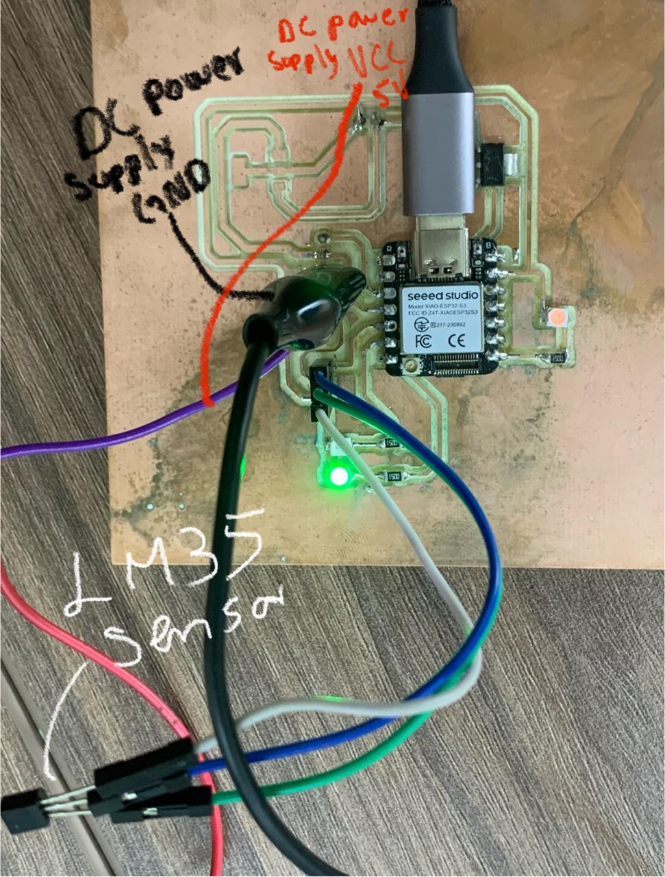
Wiring Diagram
Components:
- LM35 (Analog temperature sensor)
- Seeed XIAO (Microcontroller, 3.3V)
- 5V Power Supply
Connections:
| LM35 Pin | Connection on PCB / Microcontroller |
|---|---|
| VCC | 5V from the power supply |
| GND | GND from the power supply |
| VOUT | Analog pin (e.g., A0) on XIAO |
Notes:
- The LM35 is powered with 5V.
- The analog output (VOUT) connects directly to an analog input pin of the XIAO (like A0).
- The XIAO is powered via USB (internal 3.3V).
- A 5V regulator is needed if powering from a battery (for now you are using a 5V supply).
Basic visual diagram
                [5V Power Supply] --- [LM35 VCC]
                [Power GND] --------- [LM35 GND]
                [LM35 VOUT] --------- [XIAO A0]
                [XIAO] --------------- [PC via USB] (internal 3.3V)
Connecting the Sensor to the Microcontroller
I connected the LM35 temperature sensor to my custom-designed microcontroller board. The connections were as follows:

- VCC (5V) to the LM35 VCC pin.
- GND to the LM35 GND pin.
- Analog Output to an ADC pin on the microcontroller.
Reading Sensor Data
What is Arduino?

Arduino is an open-source electronics platform that allows users to build interactive projects by using microcontrollers. It provides a simple and flexible environment for programming and controlling hardware components. The official Arduino IDE can be downloaded from here.
To read the temperature data, I wrote a simple Arduino program that captures the analog voltage from the LM35 and converts it into a temperature reading. This program reads the sensor data, converts it to Celsius, and prints the values to the Serial Monitor every second. Additionally, it checks whether the temperature is within the normal range for fingers (28-34°C).
Why No Additional Libraries Are Needed?
The LM35 sensor provides a direct analog voltage output that can be read using the built-in analogRead() function in Arduino. Unlike digital sensors that require communication protocols such as I2C or SPI, the LM35 simply outputs a voltage proportional to the temperature, making additional libraries unnecessary.
LM35 Sensor Formula
The LM35 temperature sensor provides an output of 500 mV at 0°C, with a 10 mV per degree Celsius increase. To convert the sensor’s analog output to a temperature reading in Celsius, the following formula is used:
Temperature (°C) = (Voltage (V) - 0.5) × 100
Where:
- Voltage is the output from the LM35 sensor, typically ranging from 0.5V at 0°C to 3.0V at 250°C.
- 0.5V is the baseline output of the LM35 at 0°C.
- 100 is the scaling factor, as the sensor increases 10 mV per °C.
- In the video, we can observe how the temperature of the fingers is being measured, ranging from 24°C to 30°C. Normally, the finger temperature is between 28°C and 34°C, depending on environmental factors.
- The LM35 sensor is highly sensitive to external noise, which can affect the readings.
- The readings were stable, but probably adding a capacitor across the power lines , will helped reduce noise.
- Understand how to accurately measure body temperature using the LM35 sensor, with particular focus on finger temperature ranging from 24°C to 30°C.
- Learn how environmental factors can affect the temperature readings of the sensor and the typical finger temperature range of 28°C to 34°C.
- Gain experience comparing sensor readings with standard instruments (e.g., thermometers) to validate sensor performance.
- Understand the limitations of the LM35 sensor, particularly its sensitivity to external noise and how to mitigate this issue for reliable measurements.
See the Pen Untitled by Paula Rivero (@Paula-Rivero) on CodePen.
