05. 3D Scanning and Printing
Summary
This week we used a 3d scanner to create digital models of real objects, we also designed and printed parts that couldn't be made through substractive manufacturing.
As part of this week's assignment, I printed an object based on a model generated through 3D scanning and also printed an original design.
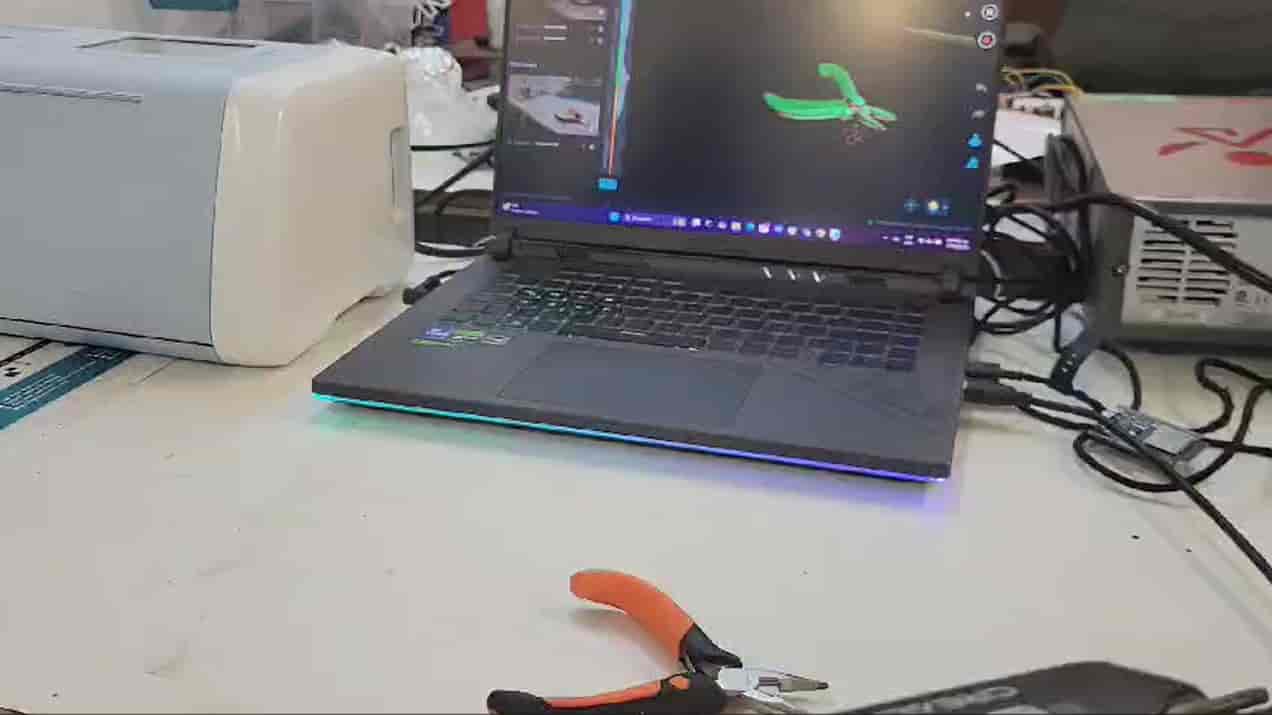
1. 3D Scanning
3D scanning is a process where we collect and analyse three-dimensional data of an object using special tools and software. This data can then be processed into a full digital model of the object, even recreating the textures and colors of the object, depending on the scanner. This process is specially usefull in reverse engineering, quality control and 3d printing.
3D scanning can be done through a variety of techniques, which are:
- Touch Probe Scanners -We use a probe to physically touch the object at multiple points to record its shape.
- Photogrametry Scanners -A series of 2D images taken from different angles are processed by software to generate a 3D model.
- Laser Scanners -A laser beam sweeps across the object, and sensors measure how the light reflects to determine the shape.
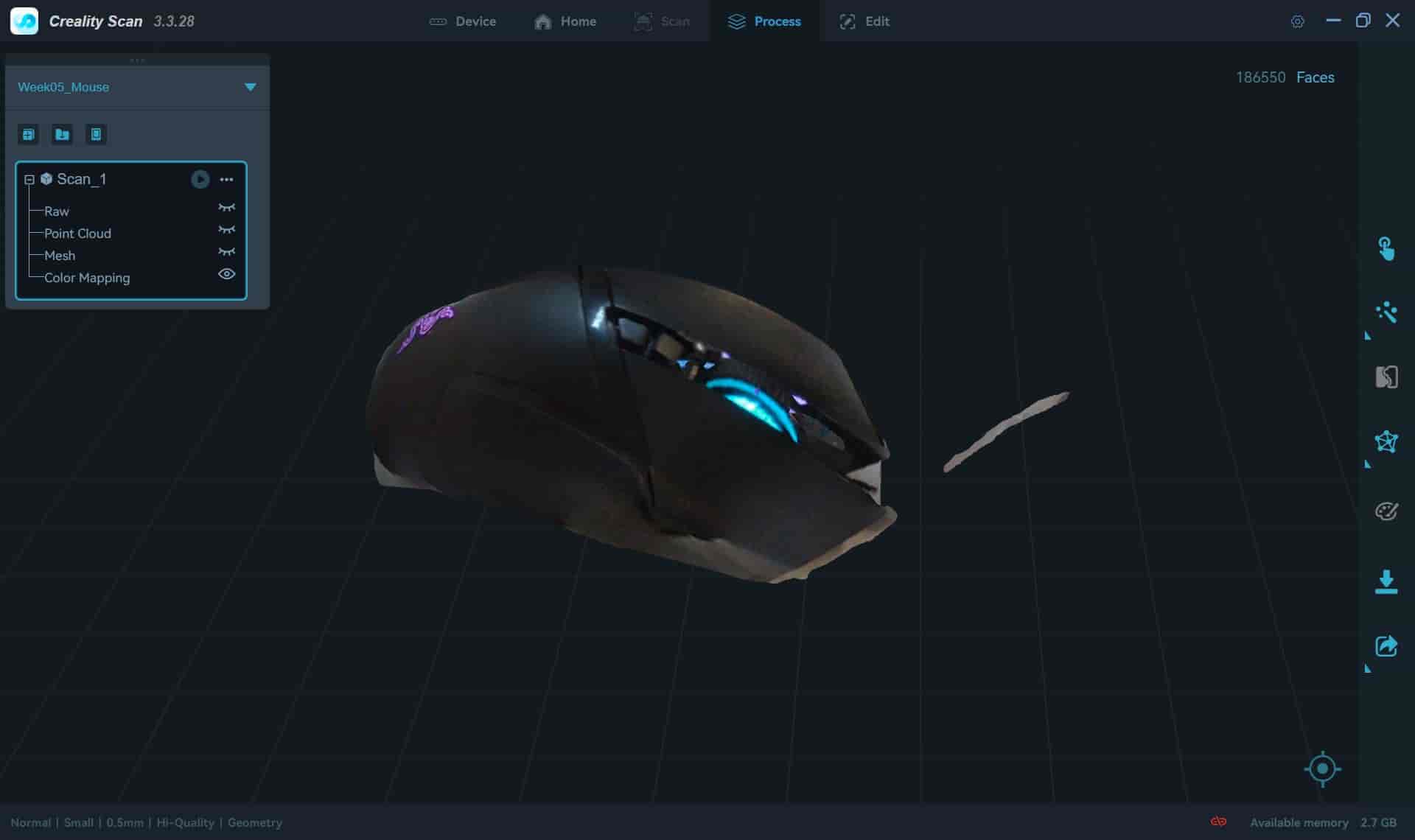
- Structured Light Scanners -A projector casts a pattern of light onto the object, and cameras analyze distortions in the pattern to reconstruct the shape. This is the one that I used this week.
- Computerized Tomography -Uses X-rays to capture multiple slices of an object from different angles. These slices are then processed by software to reconstruct a high-resolution 3D model, including both external and internal structures.
Here's how to use it:
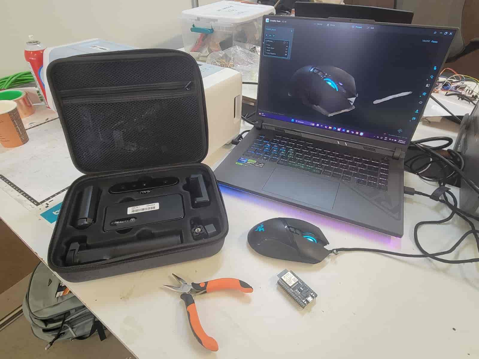
- Install software
We install the Creality Scan software and start it.
- Assemble Scanner
The scanner is separated in various components, we take them out of the case and assemble them carefully.

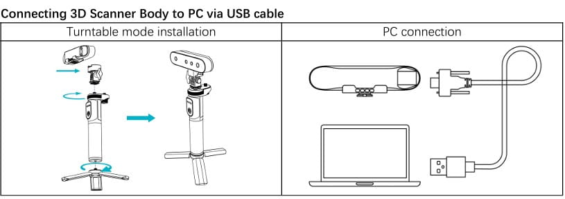
Once finished, we connect the scanner to our computers, and Creatily Scan will detect it immediately.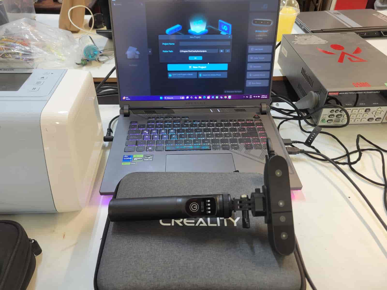
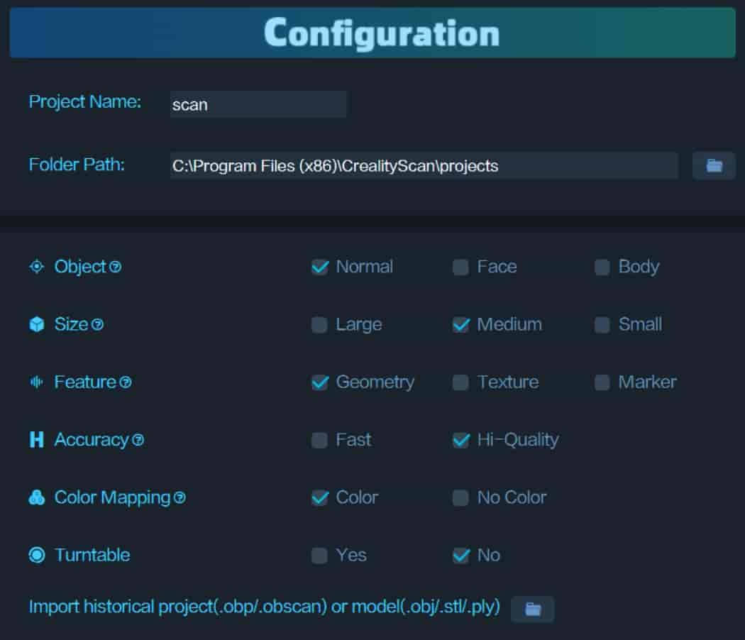
- New Project and Parameters
We create a new project and set its parameters. This will determine how big the scanned area will be, if we want the scan to be based on textures or geometries, among other properties.
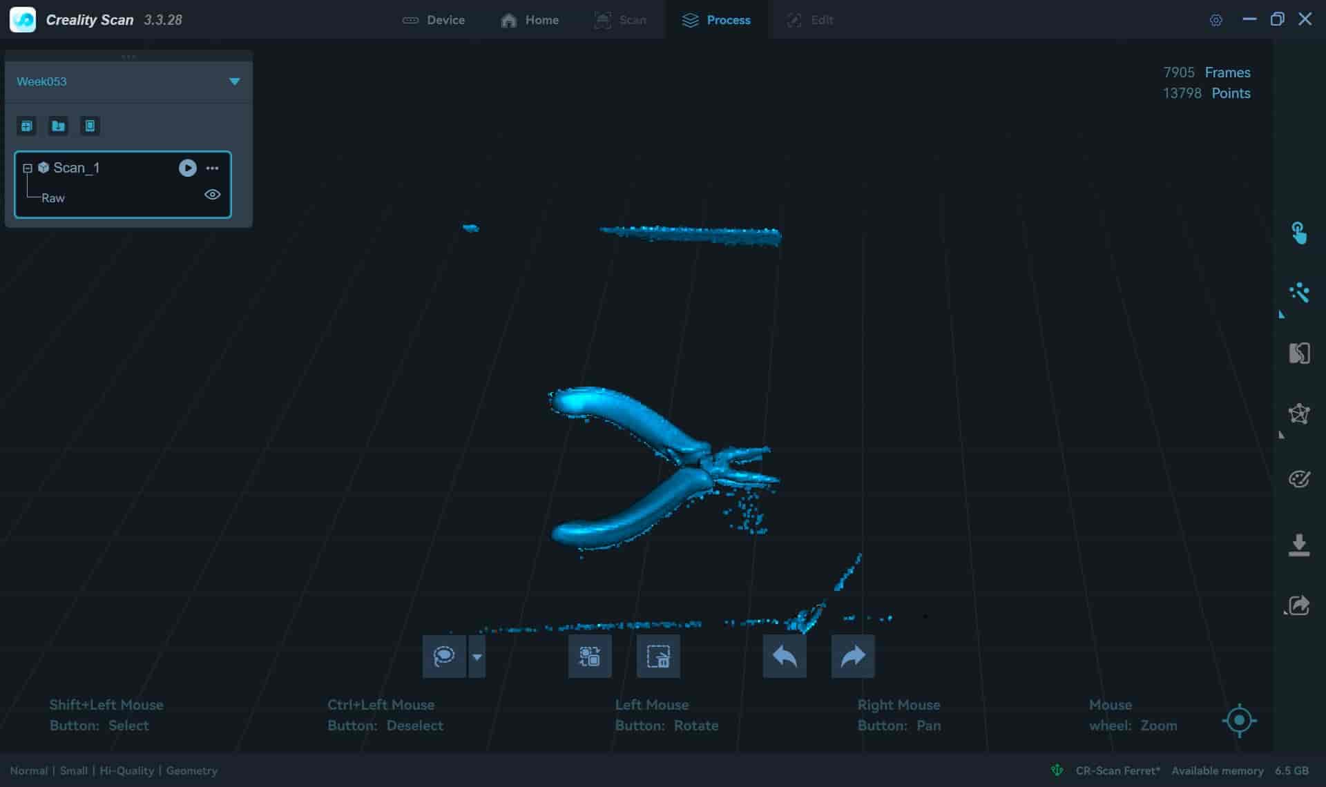
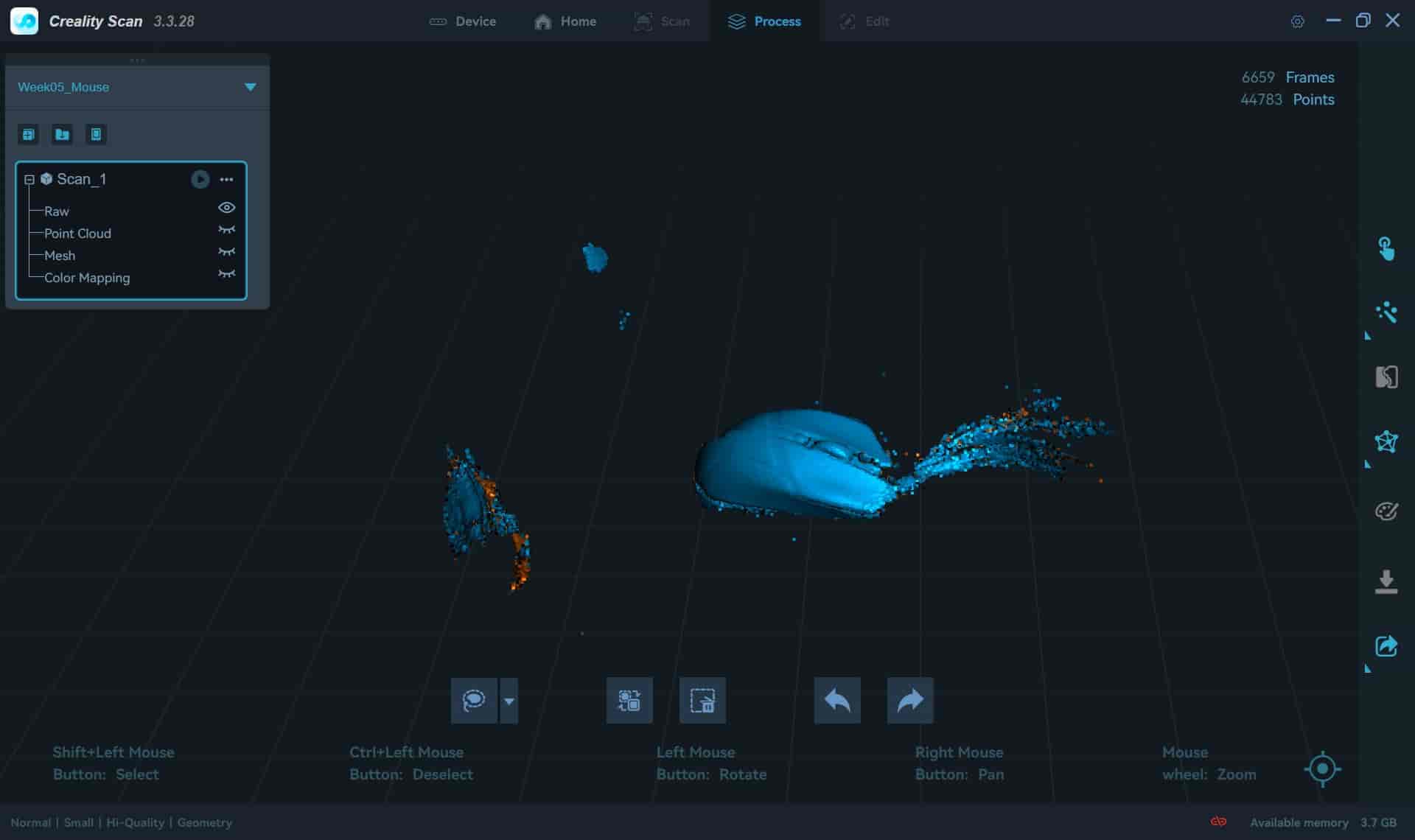
- Scanning
To scan the object we have to point the camera towards it, on the left side of our screens we will see the images recieved by the cameras, as well as a gauge that tells us if we are at a correct distance. We want to keep our object on the center of the cameras and a a distance where the gauge is green.
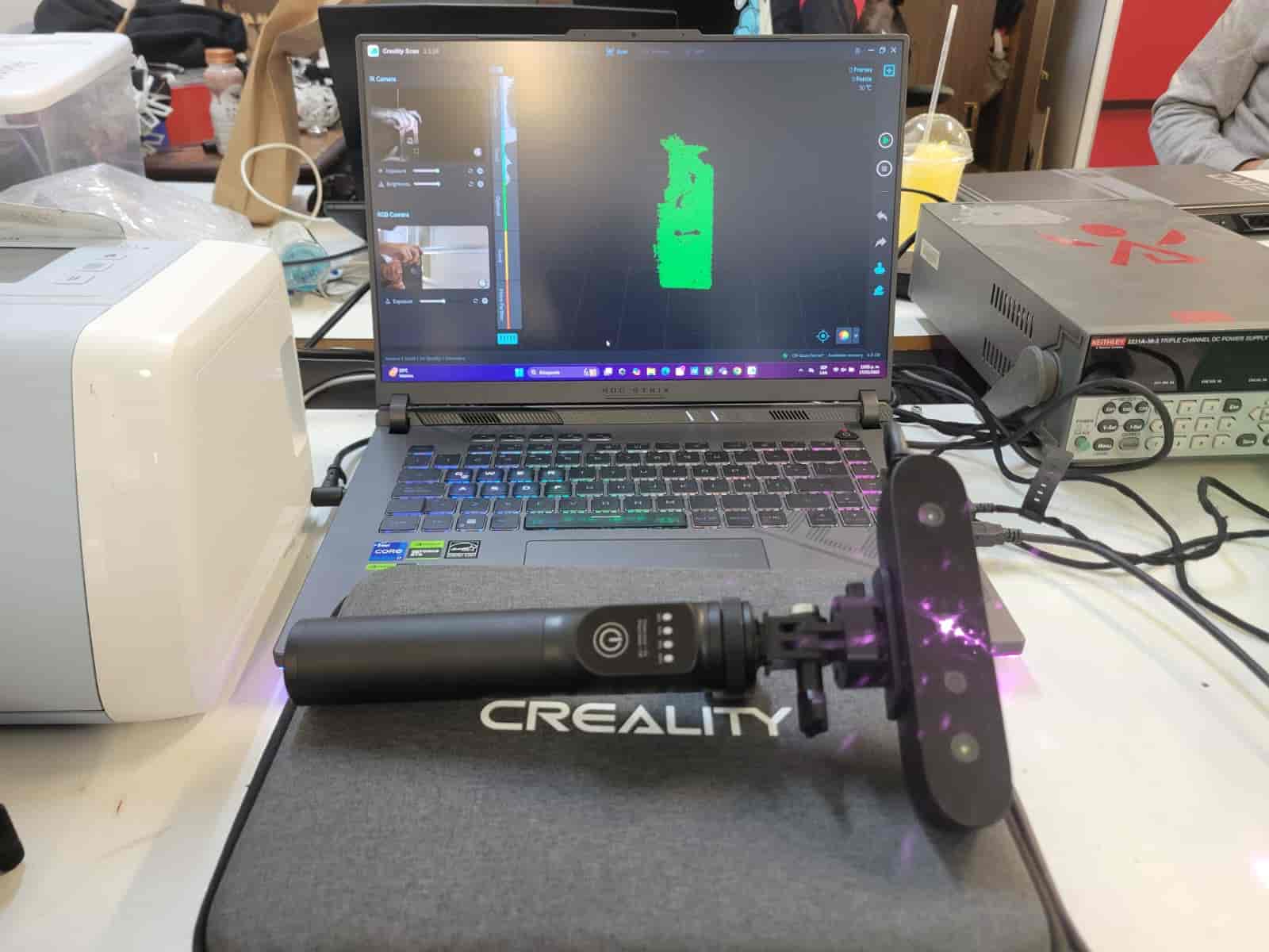
Once we are ready, we press the play button and the scan will begin.
The object will begin to be gradually generated in our computers, we have to slowly move the scanner around the object to capture as much as we can.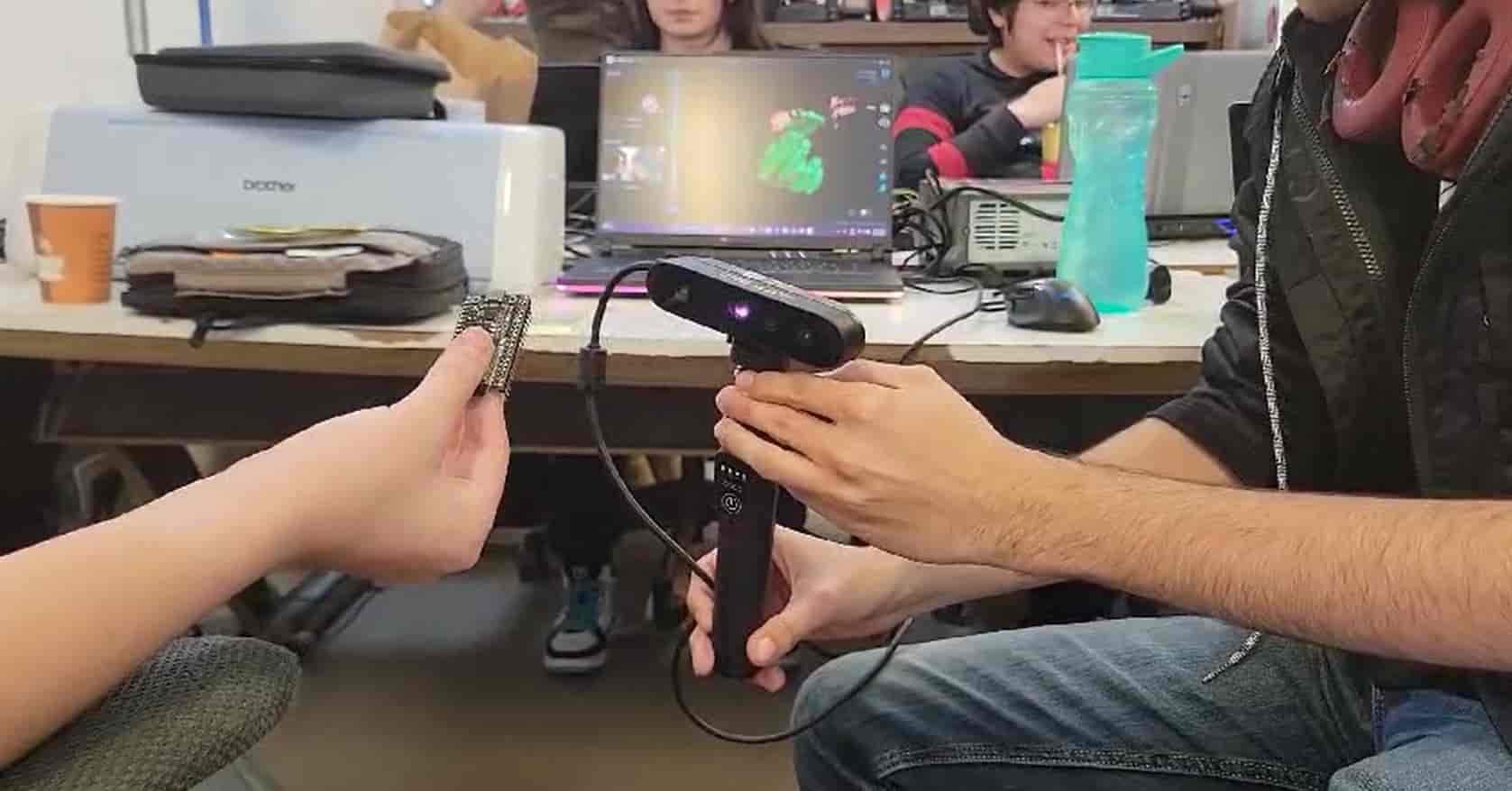
If we lose track of the object we can pause the scan and reposition ourselves, we can also undo any unwanted changes. - Processing
When we are satisfied with the scan, we press the stop button, which will take us to the editing menu.
Here we can configure the resolution, sensitivity, ammount of faces and smoothness, among other properties.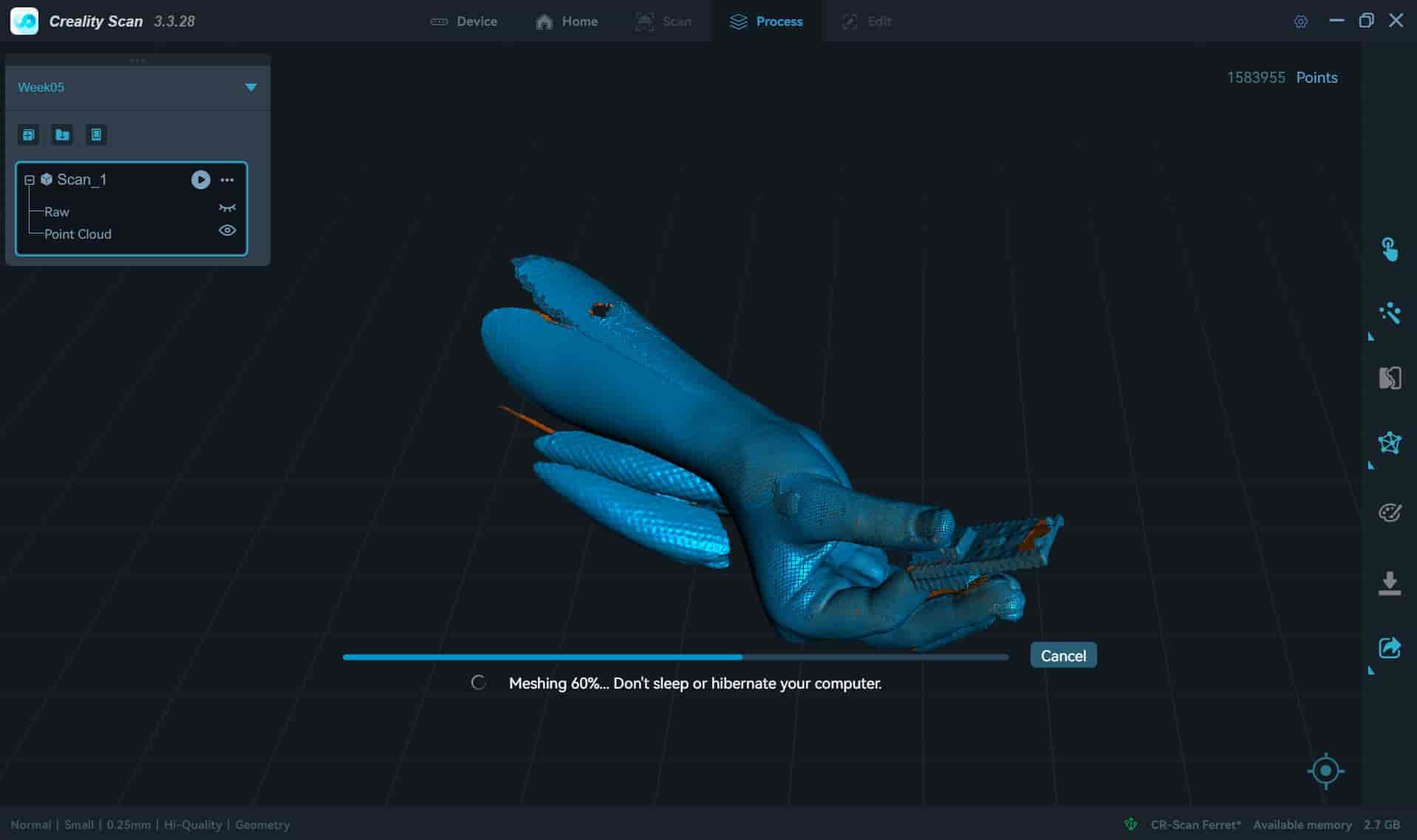
In order to optimize the size of the file, which is already massive, we should reduce all of these properties, which will decrease the quality, but not by an important margin.
Finally, we close the mesh to create a fully constrained model. - Exporting
Once we are finished, we export the model as an STL.
If the size isn't too big to handle for our computer, we can futher edit the model using a CAD software, such as SolidWorks.
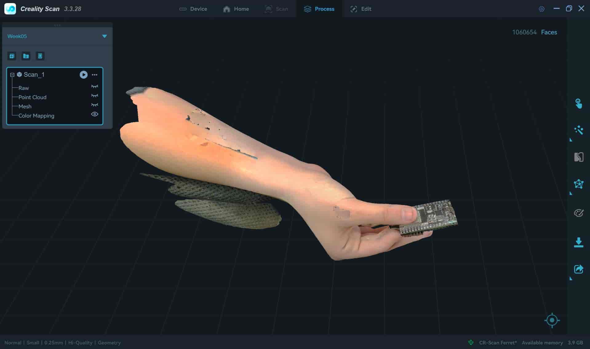
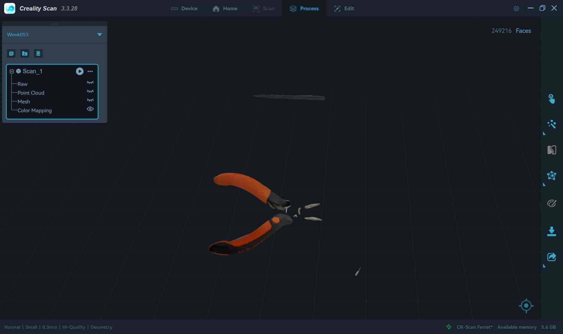
Results:
Here's this week's 3D scanning hero shot and our resulting models:
2. Additive manufacturing
Additive manufacturing is a type of manufacturing process where we build an object by gradually building it by layers. This process consumes less material than substractive manufacturing, making it ideal for prototyping.
There are different types of additive manufacturing technologies, which are:
- Fused Deposition Modelling -A heated nozzle extrudes thermoplastic filament layer by layer. This is the one that I used this week.
- Stereolithography -A UV laser cures liquid resin, solidifying each layer.
- Selective Laser Sintering -A laser sinters powder particles, usually nylon or metal, to form solid layers.
- Direct Metal Laser Sintering / Electron Beam Melting -Metal powder is fused using a laser or electron beam.
3. 3D printer testing
As part of our group assignment, we conducted a variety of tests in the Prusa Mk4S 3D printer, which produced very usefull results that I took into account when making my design.
These tests included:
- Overhang test -This test determines how far we can print without any vertical supports.
- Angled Overhang test -This test determines which angles we can print without our prints suffering from deformations.
- XY Axes Clearance test -This test determines how little space we can leave between two parts before they start sticking together, on the XY axes.
- XYZ Axes Clearance test -This test determines how little space we can leave between two parts before they start sticking together on all axes.
4. 3D printing design
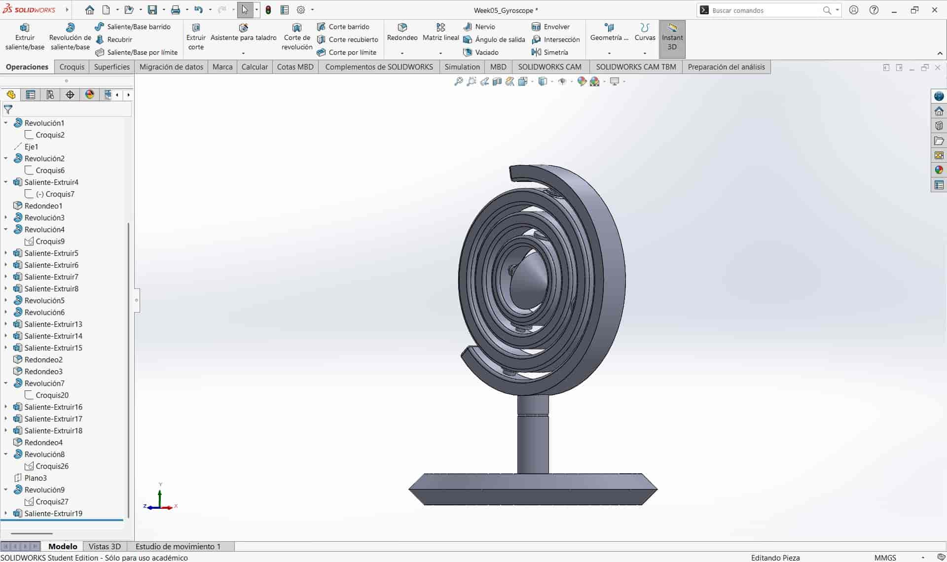
After determining the tolerances of our 3D printer, I began to work on my design, which was done in the SolidWorks CAD software.
I wanted to create an assembly of parts with lots of movement, so I went for a small, gyroscope design. Since this design is an assembly of six different individual parts, the space between the joints could not be made subtractibely.
4.1 New Project and Parameters
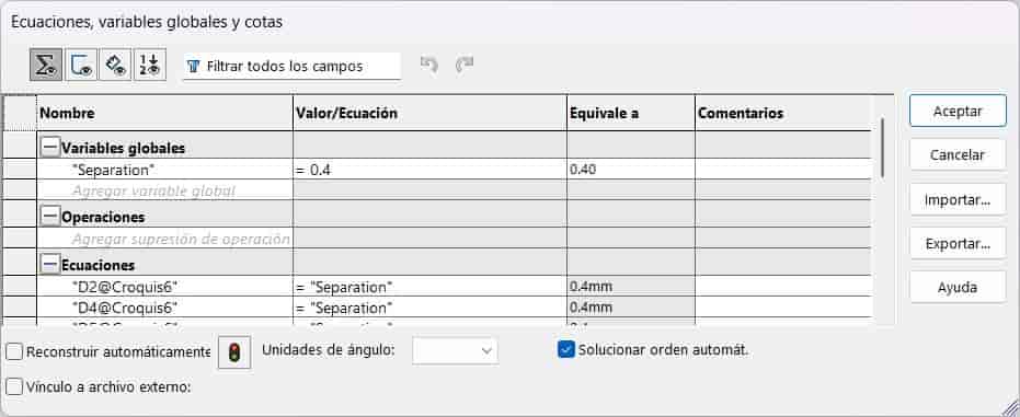
I create a new part document an immediately set up a new parameter, which will control how much space we leave between each individual part.
This parameter was based on the clearance tests conducted on the Prusa MK4S, since my Bambu Lab P1P has a similar performance.
4.2 Base
I create a sketch on the front plane and draw half of the base, this is because I will be using the revolve feature extensively in this design.
I finish the sketch an subject it to the revolve operation, creating our base.
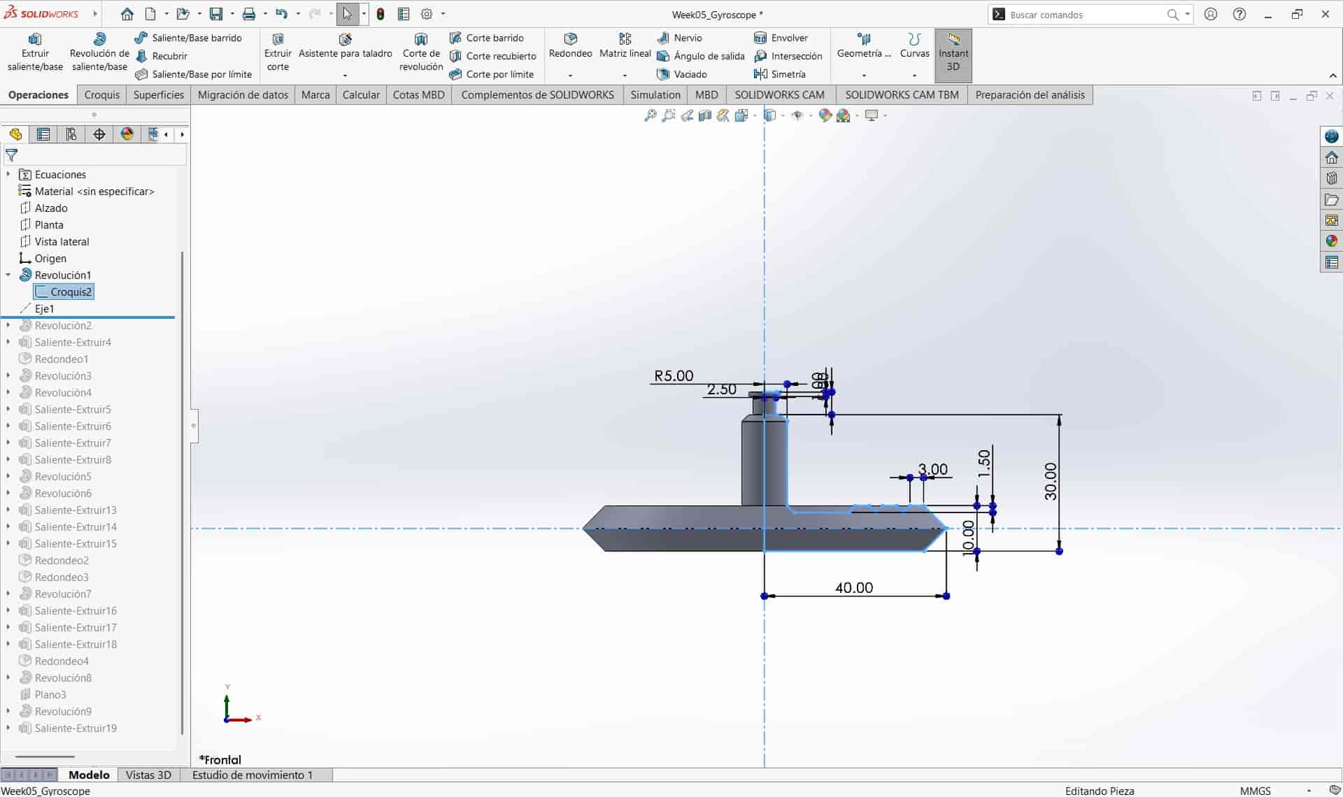
4.3 First joint
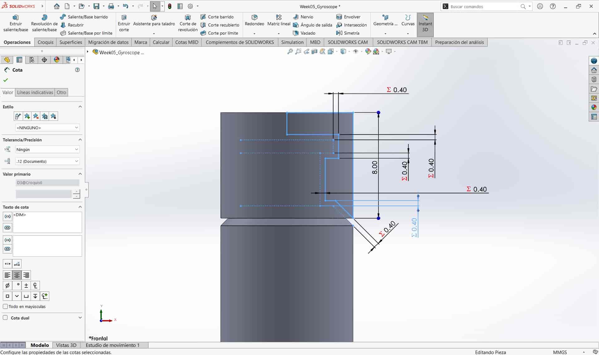
I designed the first joint as a cylindrical shape, leaving the necessary gaps between parts to ensure mobility, to do this I used the separation parameter, in case I needed to modify these gaps later, which proved to be a very insightful move.
I once again used the revolve operation.
4.4 First ring
I create a new sketch and draw the first ring, cutting off a section for aesthetic purposes, I then use an extrude operation.

Then I designed the joints that will support the next ring, using the parameterized separation once again.
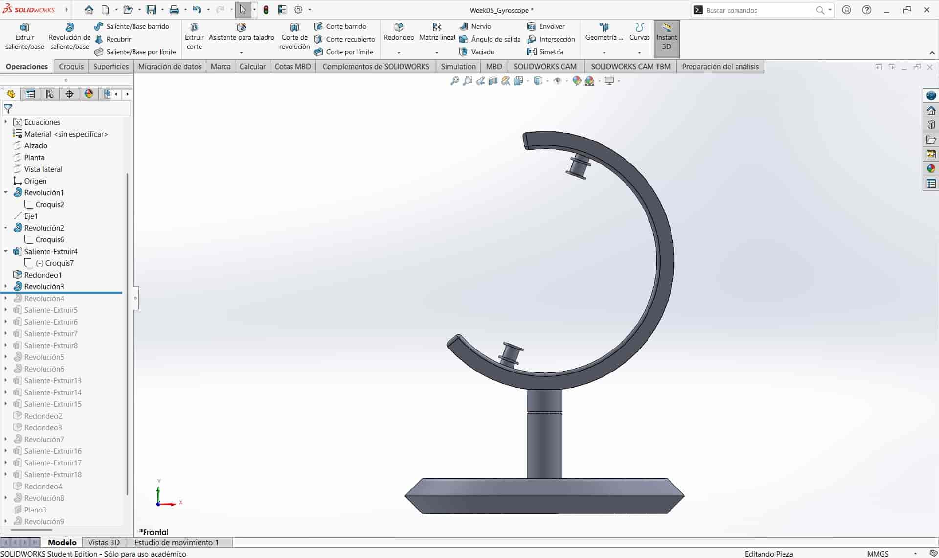
I followed this process to create the subsequent rings, with minor variations in dimensions.
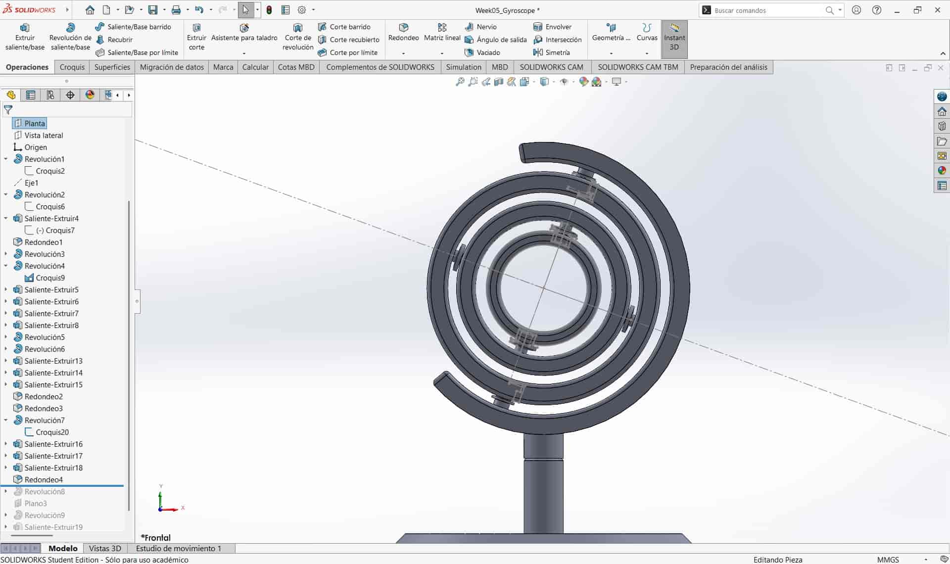
4.5 Internal Rings
As stated before, I followed the same design principles to create the three inner rings, changing the position of joints to be perpendicular to the ones of the adjacent rings, in order to create a more dynamic design.

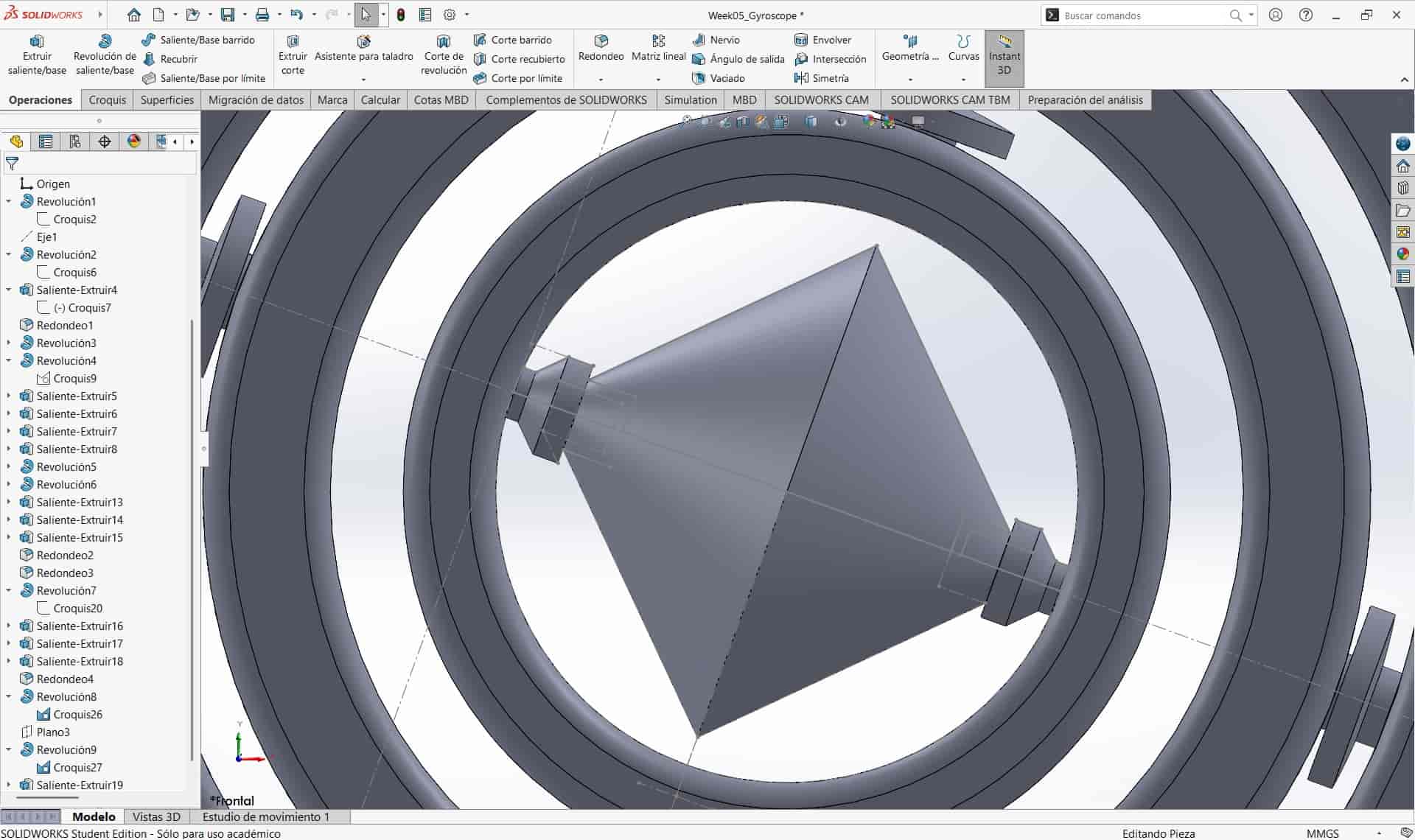
I created three inner rings and left enough space for a part at the center, which I chose to be a bicone.
4.6 Final Joints and Bicone
I designed half of the final joints and the bicone and subjected the sketches to a revolve operation.
With this, the design was complete.
4.6 Corrections
I showed the design to my local evaluator and he said that the gaps weren't big enough, this was because to create my parameter, I took into account the results of the horizontal clearance test, not the vertical one, which meant that the joints would be too tight or could potentially get stuck together.
No big deal, since we used a paremeter, I simply changed the value from 0.2 to 0.4 mm as adviced by my evaluator, which proved to be a good decision.
5. Slicing
Once we have our models, we need to use a special type of software called a slicer, which will turn the model into instructions that the printer can understand.
I used PrusaSlicer for the scanned model of my mouse and Bambu Studio for my gyroscope. Let's take a look at each one, shall we?
5.1 PrusaSlicer
- Getting Started
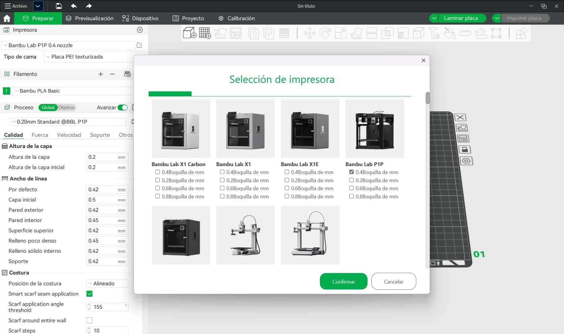
The first time we open PrusaSlicer after donwloading it, we will be asked to input the model of printer and type of material that we will be working with.
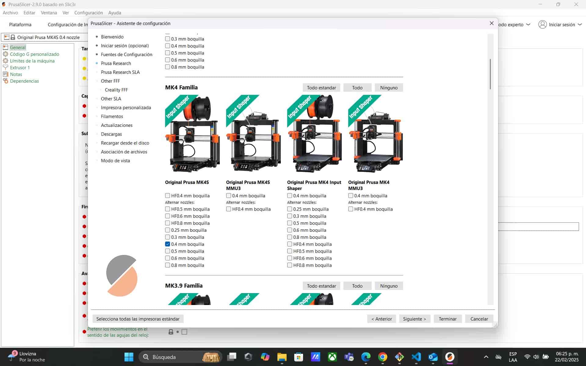
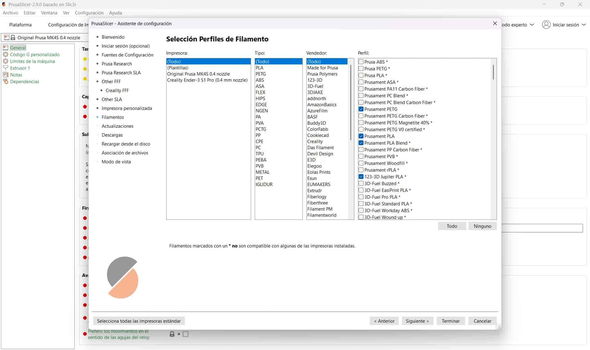
The printers that I chose were the Prusa MK4S and Creality Ender 3 S1 Pro, and our chosen material is PLA. Unfortunately, Bambu Lab printers aren't compatible with the Prusa Slicer, so I won't be able to use it with my printer.
It's important to choose the correct nozzle diameter of our printer in case it has multiple nozzle options, in my case I'm working with a 0.4 mm nozzle. - Import STL
We import our STL file into the slicer.
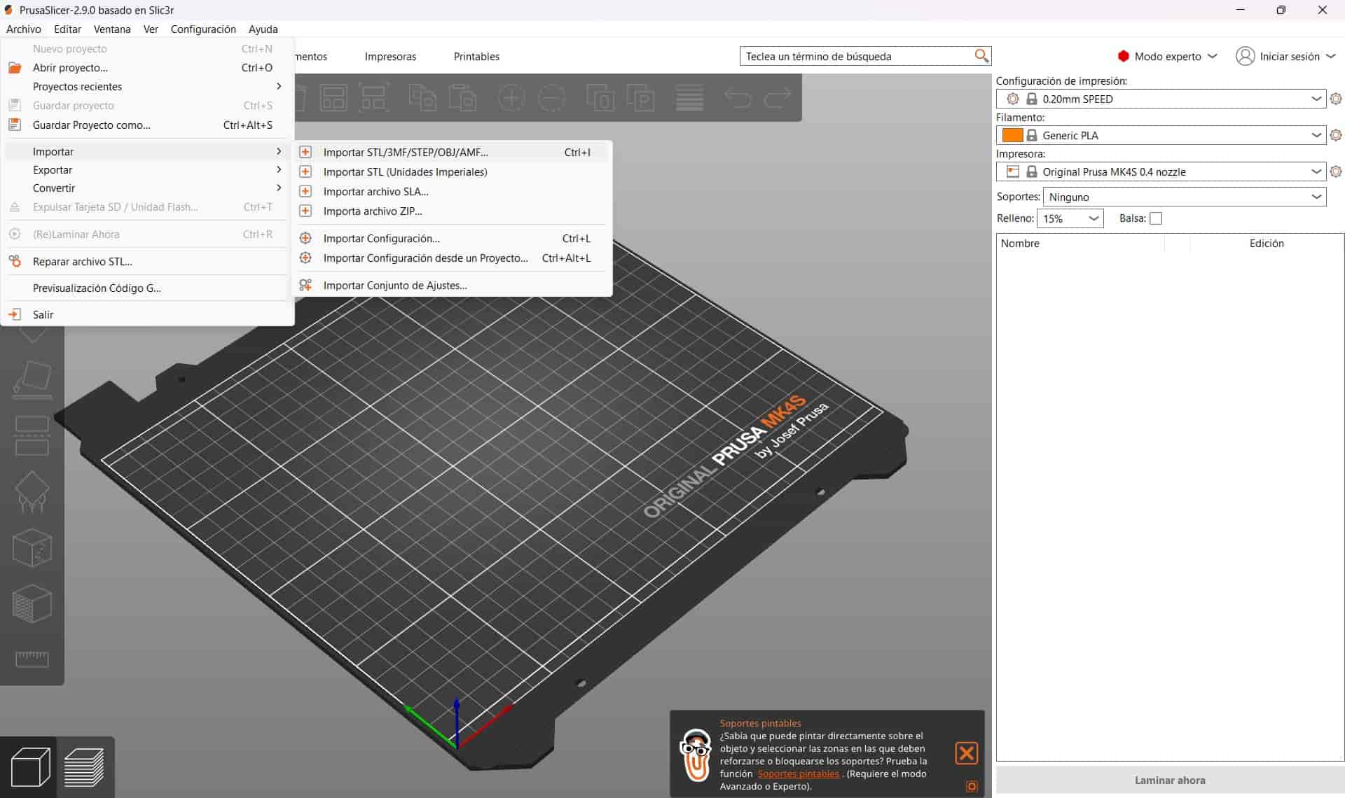
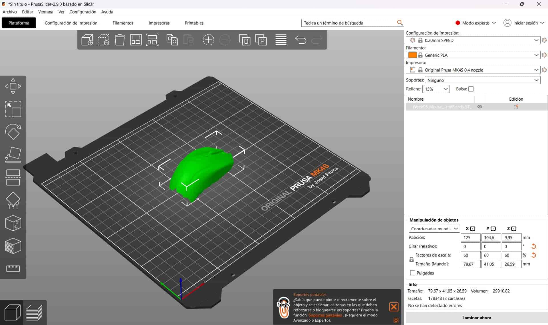
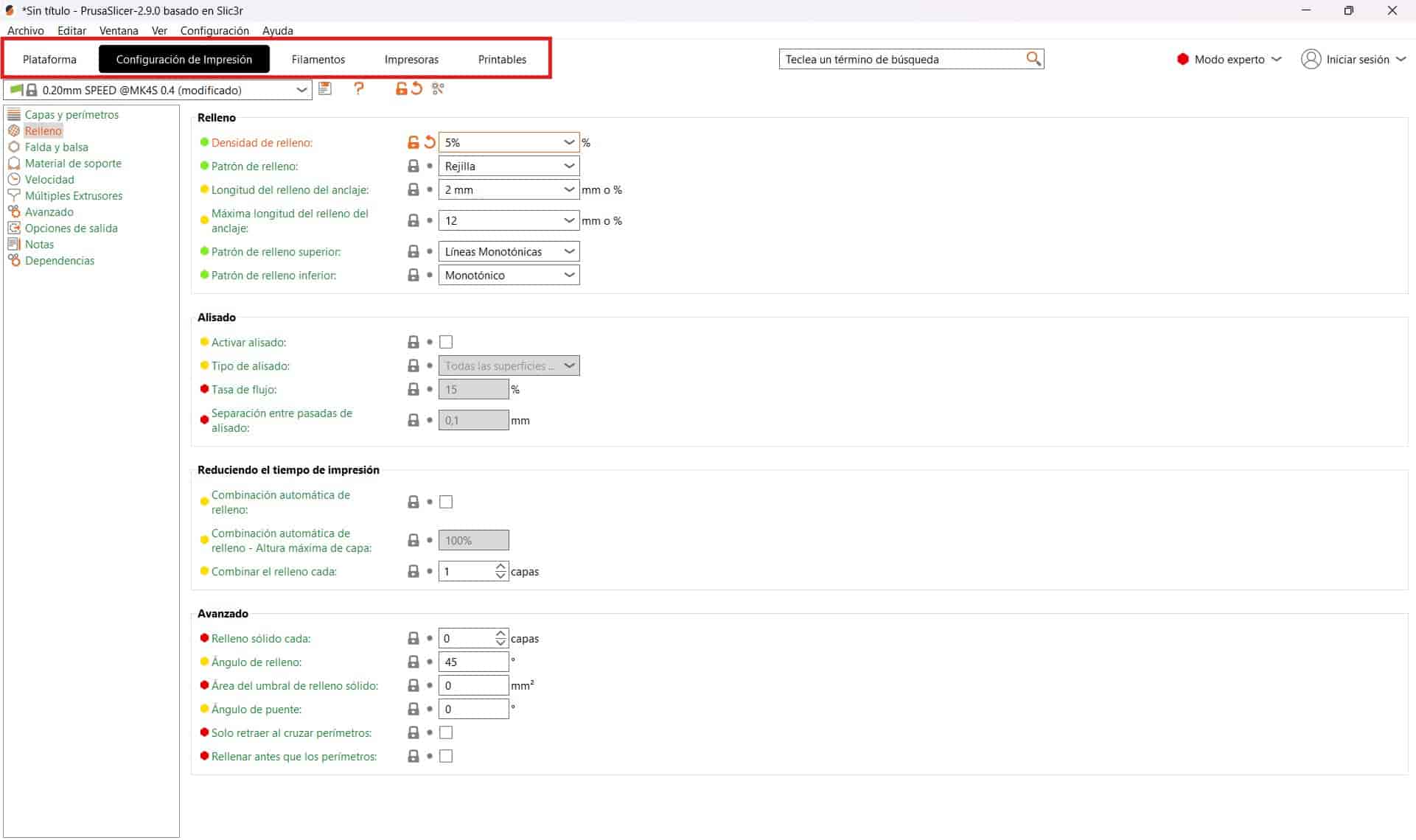
- Settings
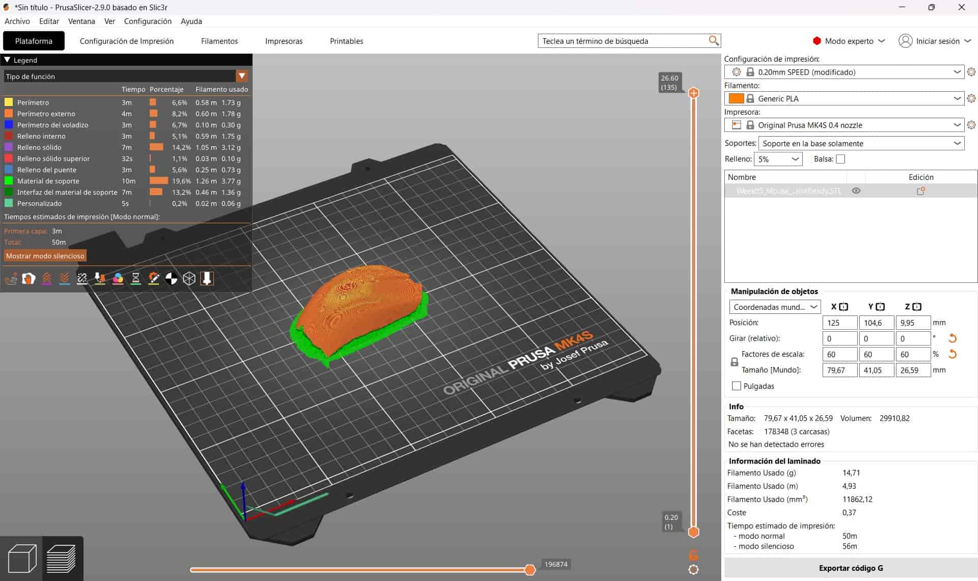
We change the settings that we consider necessary for out print, in my case, I use the default settings with the exception of the infill, which I change to 5%, apply supports in the base and choose the MK4S as our printer.
- Slicing and Exporting
Once we are finished with our settings, we can slice our model, which will divide it into the layers that will be printed. The sliced model is divided into colors that tell us about the properties of that particular section of the print, we can also see the estimated printing time.
If we are unsatisfied with the slice, we can change the parameters and repeat the slice until we get the expected results.
Once done, we export the sliced model as G-code, which is the code that will tell the machine exactly what to do.
5.2 Bambu Studio
- Getting Started
Not unlike PrusaSlicer, the first thing we do is select our printer and material, I chose the 0.4 mm nozzle Bambu Lab P1P and the Ender 3 S1 Pro, I chose Bambu PLA Basic as my material.
If we have a Bambu Lab account, we can use it to log into Bambu Studio, bringing with it all of our registered devices and settings. - Import STL
We import the STL file into the slicer.
- Settings
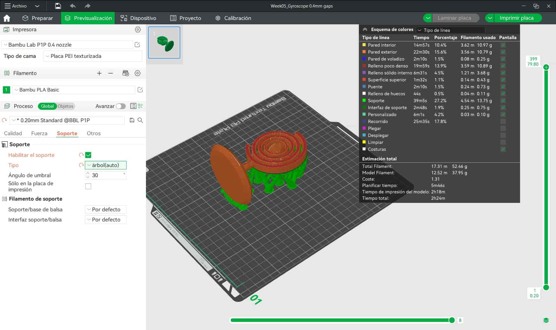
First, I rotated my model 90 degrees on the X axis, which will set the flat faces of the rings parallel to the bed. I did this in order to improve stability and make sure that the gaps don't stick together due to the weight that would have been exerted on the joints if we were to print the model starting from the base.
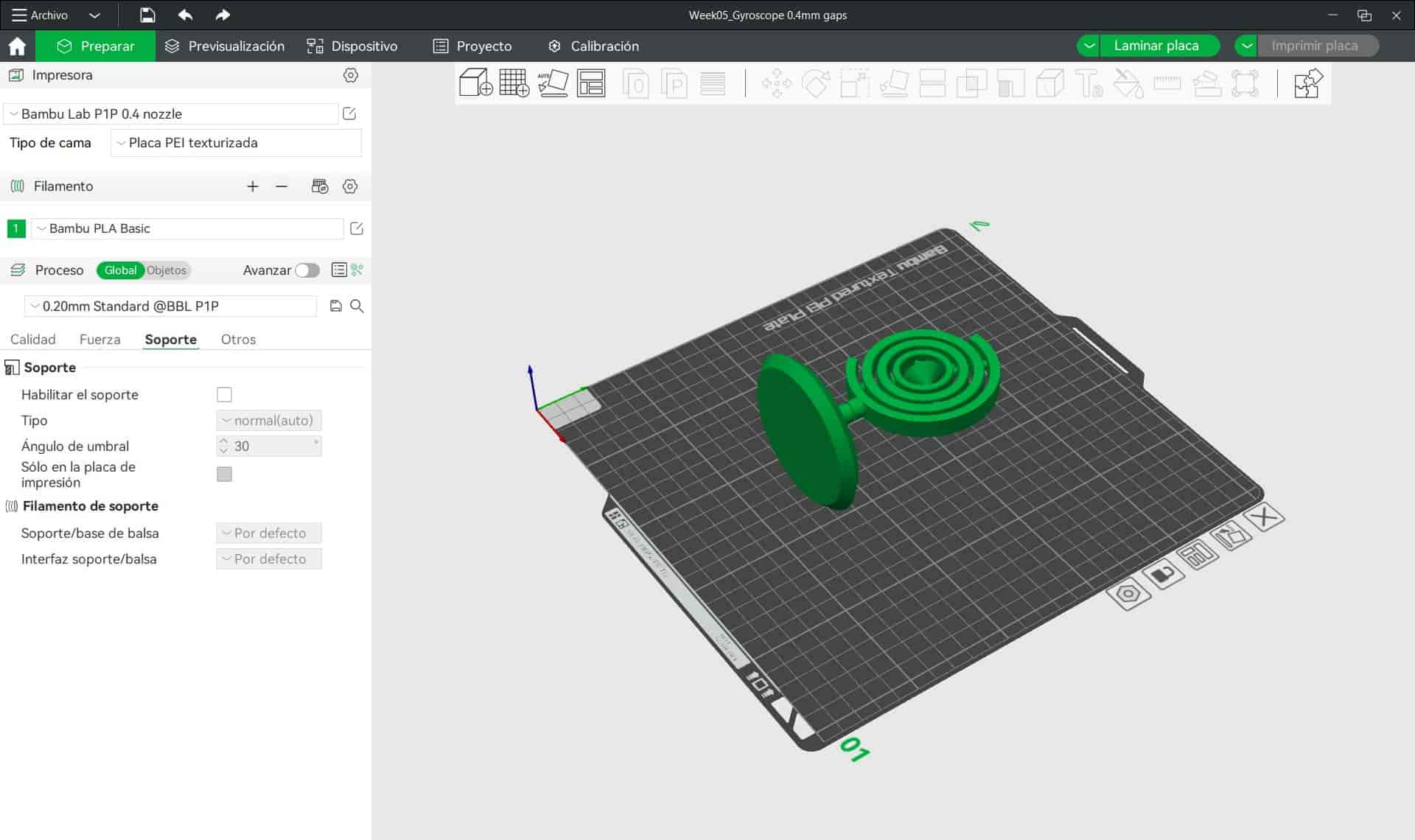
The settings I changed were the infill, set at 5%, top surface layers reduced to 3, and generated automatic organic supports. - Slicing
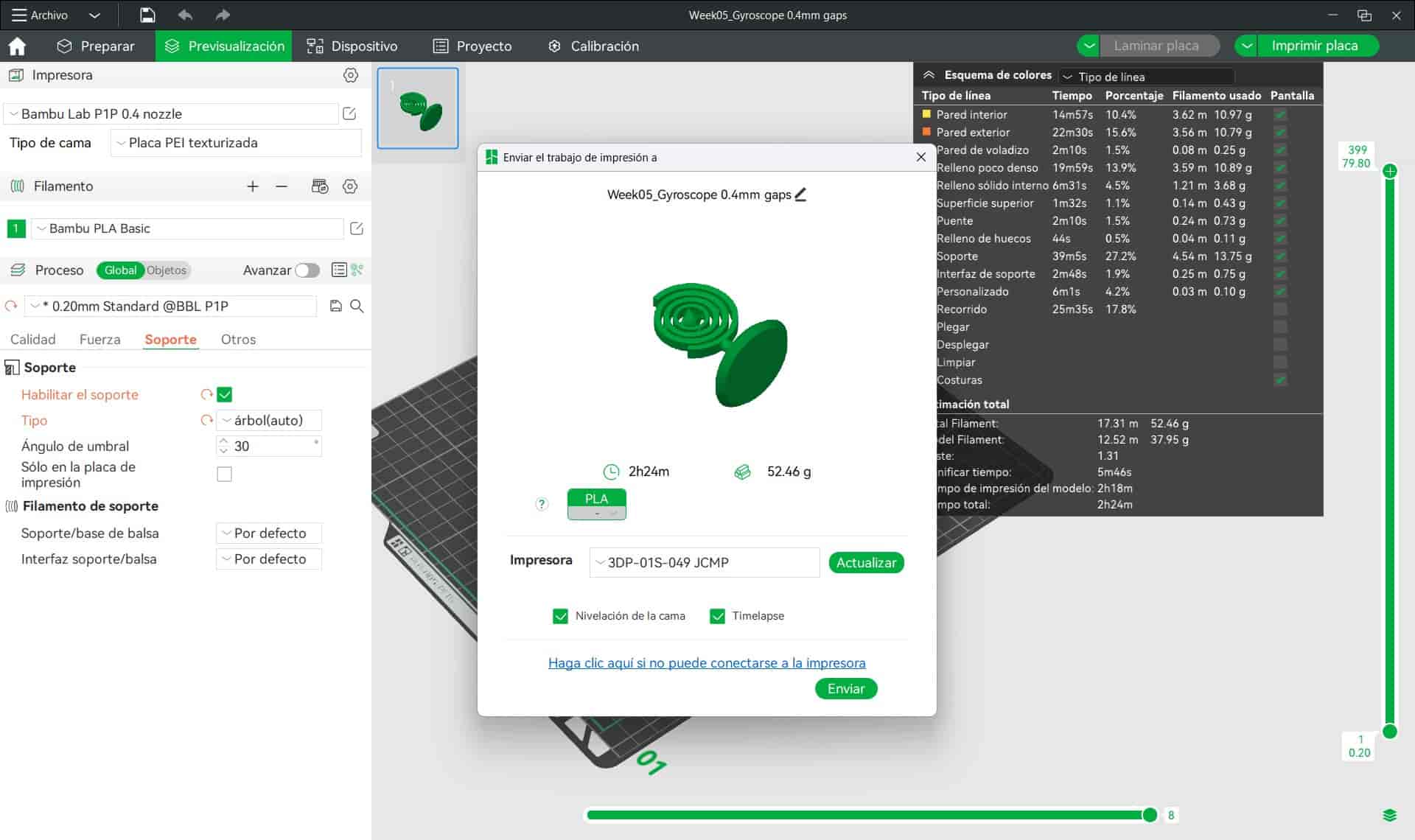
Once finished, I sliced the model. Unlike the MK4S and Ender 3, the P1P doesn't require a physical drive to recieve and print objects, this is instead done directly through Bambu Studio, which sends the model to the printer using a Wi-Fi connection.
6. Printing
Once our models have been sliced and our G-code files are ready, we can proceed to use the 3D printer.
6.1 Prusa MK4S
- Loading Files
On the right side of the control panel of the printer we will see a USB drive, we will remove it, insert it into our computer and load the G-code file. We then extract the drive and insert it back into the printer.
- Selecting File
To navigate the control panel, we can use the knob on the right or use the touch screen. We will select the file menu and navigate to our desired file.
- Begin Printing
Select the print option and the process will begin. The printer will start by calibrating itself each print and purging a small ammount of filament, after which it will begin to print the object.
When we are printing, we should supervise the machine to ensure everything goes smoothly, stoping the print in case we detect any kind of failure. - Extraction and Cleaning
Once our print has finished, we remove the plate on top of the heatbead and bend it slightly until our object is detached, we may also use a scraper if necessary, just be careful not to scratch the plate.
After removing all of the plastic from the plate, we should clean it with isopropyl alcohol and place it back on the heatbead.
6.2 Bambu Lab P1P
- Loading Files
As stated before, we can use the Bambu Studio to print our object without even touching the printer.
Once our model is sliced, we select the print option and a menu will be displayed. We will select our printer and send the file. - Begin Printing
After our printer has recieved the files, we will go to the device menu, here we can monitor and manage several aspects of the process, such as speed and temperature.
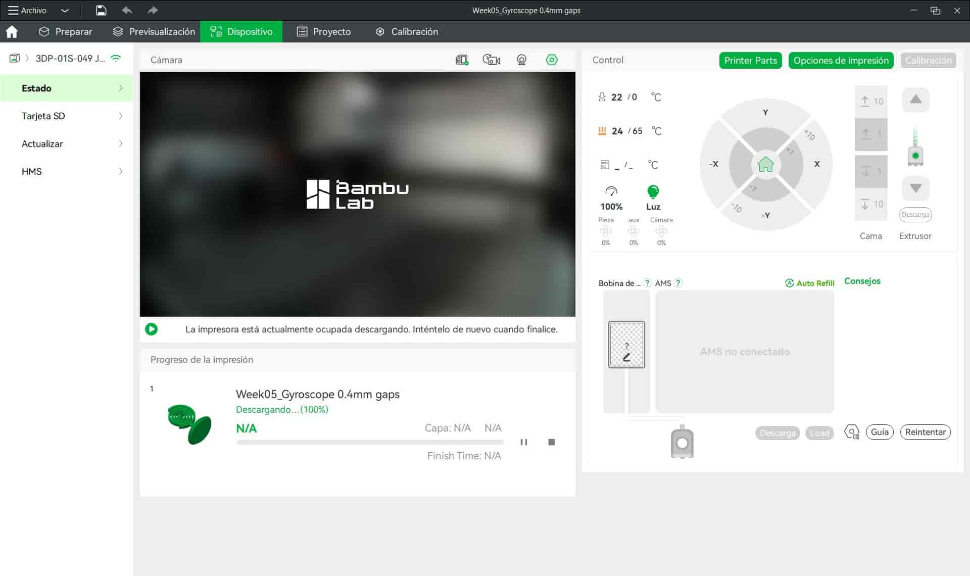
We can also activate the integrated camera, which will record the process to generate a timelapse or to allow you to monitor the process from the mobile app. This means that you could be printing your projects while away for school or work, just keep track of the process in case something goes wrong and you need to stop it.
At this time, the printer will perform a self calibration and purge some filament, after which it will begin printing our object.
Just like we did with the MK4S, we will monitor the process in case we need to stop it. - Extraction and Cleaning
Just like the MK4S, remove the plate and bend it slightly until the object detaches or use a scraper.
Clean all remaining plastic from the plate, give it a scrub with isopropyl alcohol, and place it back on the heatbed.
7. Results
This is this week's 3D printing hero shot:
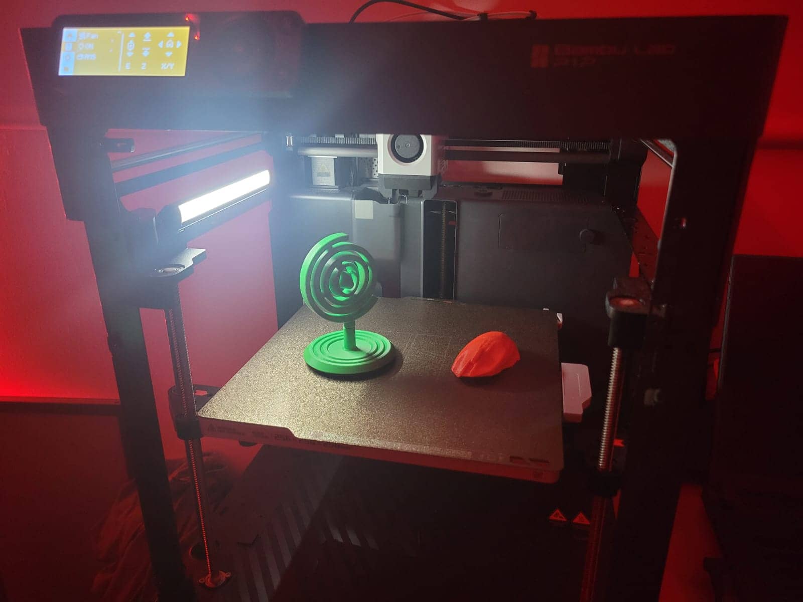 I can say that I am very satisfied with both prints, both the MK4S and P1P are remarkable machines, combining incredible efficiency with quality and precision, while remaining extremely user friendly.
8. Comments and Recommendations
This was a fun week! I want to thank my peers Maria de Lourdes Diguero and Javier Osorio for helping me during the scanning process.
I recommend using a powerfull enough computer for the scanning process, since it takes quite a bit of processing power.
9. Learing Outcomes
This week I succesfully learned how to scan an object using a handheld structured light scanner, and I succesfully printed objects using two different slicing software and 3D printers.