04. Embedded Programming
Summary
This week we were introduced to embedded programming through online simulators. As part of my individual assignment, I researched and programmed two different microcontrollers in a simulated environment, and replicated one of the circuits in physical form. For our group assignment, we took a look at various microcontrollers and programming languages.
1. Embedded Systems
An embedded system is a type of highly specialized computational system. These systems have a wide variety of forms and applications, some of which are microcontrollers, microprocessors, application-specific integrated circuits, embedded graphics processing units and neural processing units, among others.
These systems can vary greatly in architecture and functionality, but they share some key features:
- Specific purpose - Embedded systems are designed to perform a specific task or small set of related tasks.
- Hardware and software integration - Embedded systems combine hardware and software into compact, optimized designs, often with limited or no possibility for hardware modifications.
- Processing limitations - Embedded systems often have limited processing power, memory, and storage compared to general-purpose computers, due to their nature as systems designed for specialized functions.
- Real-time operation -Many embedded systems must process tasks within strict time limits, ensuring fast and predictable responses to inputs.
- Low power consumption - Embedded systems are designed to operate efficiently with small ammounts of energy, often running on batteries or low-power sources for extended periods.
- Firmware - This is a type of specialized software stored in an embedded system's non volatile memory, retaining the information even when there is no power. It is optimized for efficiency and reliability, with some systems allowing updates while others cannot be modified.
- Specialized OS or no OS at all - Some embedded systems use simple, real-time operating systems, optimized for efficiency and reliability. Others run only on their firmware, without any OS at all.
2. Microcontrollers
A microcontroller is a compact integrated circuit that combines a processor, memory, and input/output peripherals on a single chip, designed for specific tasks. Its firmware acts as the interface between software and hardware, controlling all of the chip's operations. Stored in non-volatile memory, the firmware ensures the device retains its information even after power loss.
Microcontrollers are divided into families based on their architecture, manufacturer, and intended applications. Each family shares a common instruction set, peripheral design, and development tools, ensuring compatibility across different models. Some of the most well known families include AVR, STM32, ESP32, RP2040 and RISC-V, but there are many, many more, tailored to specific functions and with a variety of capabilities. Choosing a microcontroller family allows us to work with familiar tools and code structures while scaling projects to different performance levels.
To use our microcontroller, we have to write and upload the firmware to control its operation and interactions with external components. We typically write code in languages like C, C++, or MicroPython using an integrated development environment or IDE, such as Arduino IDE, Thonny or VS Code with the help of extensions. The code is then compiled and uploaded onto the microcontroller via a USB or serial connection. Once programmed, the microcontroller can process inputs, process those inputs according to our programing, and produce outputs that we can use to control actuators like motors or LEDs. Additionally, we can establish communications with other devices through a variety of protocols.
The microcontrollers that I researched and simulated for this week's assignment are Raspberry Pi's RP2040 and Espressif's ESP32.
3. RP2040
The RP2040 is Raspberry Pi's debut microcontroller, designed to be a low-cost, high performance microcontroller with flexible digital interfaces.
Here is a summary ot it's key features:
- Dual Cortex M0+ processor cores, up to 133MHz - The RP2040 has two low-power ARM Cortex-M0+ cores that run at a maximum clock speed of 133MHz, allowing for efficient multitasking and parallel processing.
- 264kB of embedded SRAM in 6 banks - The microcontroller includes 264KB of fast-access SRAM, divided into six memory banks, improving performance.
- 30 multifunction GPIO -The circuit has 30 General Purpose Input/Output or GPIO pins, which can be configured for various functions such as digital I/O, PWM, and communication interfaces.
- 6 dedicated IO for SPI Flash (supporting XIP) - The RP2040 has six dedicated pins for external SPI Flash storage, enabling Execute-In-Place (XIP) functionality for running code directly from flash memory.
- Dedicated hardware for commonly used peripherals - It includes built-in controllers for peripherals like UART, I2C, and SPI, reducing CPU workload and improving real-time performance.
- Programmable IO for extended peripheral support - The RP2040 features Programmable I/O blocks, allowing users to create custom hardware interfaces and communication protocols without CPU overhead.
- 4-channel ADC with internal temperature sensor, 500ksps, 12-bit conversion - The analog-to-digital converter supports four channels, with a 12-bit resolution and up to 500k samples per second. It is also equipped with an internal temperature sensor.
- USB 1.1 Host/Device - The microcontroller supports USB 1.1 communication, allowing it to function as either a USB host to connect peripherals or a USB device to communicate with a computer.
4. ESP32
The ESP32 is a family of microcontrollers developed by Espressif Systems. These microcontrollers share a common architecture while varying in features such as processing power, memory, and wireless capabilities.
Some of the ESP32 variants are:
- ESP32 - The original dual-core Xtensa LX6 architecture variant with Wi-Fi, Bluetooth Classic and BLE 4.2.
- ESP32-S2 - A lower-cost, single-core Xtensa LX7 architecture variant with Wi-Fi but no Bluetooth, featuring USB-OTG and enhanced security.
- ESP32-S3 - An upgraded dual-core variant with BLE 5.0, AI/ML acceleration, and more GPIO.
- ESP32-C6 - A RISC-V-based variant with Wi-Fi 6, BLE 5.0, and support for Thread & Matter protocols.
- ESP32-P4 - A high-performance RISC-V-based variant without Wi-Fi nor Bluetooth, trading off wireless connectivity in exchange for higher proccessing power. It features USB, PCIe, and camera interfaces.
For this week's assignment, I used the ESP32-S3 in my simulation, so let's take a closer look into this microcontroller.
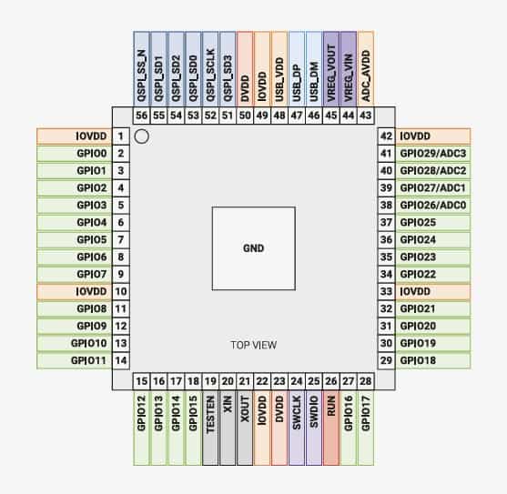
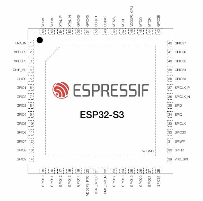
4.1 ESP32-S3
The ESP32-S3 is a more advanced variant of the ESP32-S2, with improvements in performance, advanced connectivity, AI acceleration, and higher GPIO availability.
It's key features are:
- Dual-core Xtensa LX7 processor - Runs at up to 240 MHz, offering greater performance than previous models.
- Wi-Fi 4 IEEE 802.11b/g/n-compliant - Provides wireless connectivity for IoT and embedded applications.
- Bluetooth 5.0 - Supports BLE 5.0 with extended range and higher speed.
- AI Acceleration - Includes vector instructions for optimized AI/ML processing.
- USB-OTG support - Allows direct USB device connections for peripherals.
- Increased GPIO count - Equipped with 45 programmable GPIOs, more than previous ESP32 models, allowing us to build bigger systems.
- External Flash and PSRAM support - Supports up to 16 MB of external flash and additional RAM for advanced applications.
- Security - Capable of flash encryption and Secure Boot v2 for enhanced security.
5. Development boards
A development board is a piece of hardware designed to help us in the development process of a microcontroller-based system. These boards are equipped with many features, such as power inputs and regulators, I/O interfaces, programming interfaces and a variety of peripherals, depending on the board's intended applications.
Some well known development boards are:
- Raspberry Pi Pico - Equipped with the RP2040 microcontroller, designed for cost-effective and flexible embedded applications.
- Seeed Studio XIAO RP2040 - Also based on the RP2040, but in a very small configuration, of 20x17.5mm to be precise, making it ideal for wearable or compact projects.
- ESP32 Dev Boards - Equipped with different ESP32 variants, such as the ESP32, ESP32-S2, or ESP32-S3, each with different capabilities, as explained in section 4.
- Arduino Uno - Uses the ATmega328P microcontroller, a widely used 8-bit MCU with a large ecosystem and beginner-friendly support.
- Arduino Mega - Powered by the ATmega2560, featuring 54 GPIO pins and additional memory, making it suitable for bigger projects requiring multiple peripherals.
- Arduino Nano - A compact board using the ATmega328P, similar to the Uno but with a smaller dimentions.
The development boards that I simulated for this assignment were the ESP32-S3-DevKit-C1 and the Raspberry Pi Pico, additionally I used a XIAO RP2040 to conduct a physical test of the simulated circuit, which I will get into later.
Here is a general overview of these dev boards:
ESP32-S3-DevKit-C1
Pin layout:
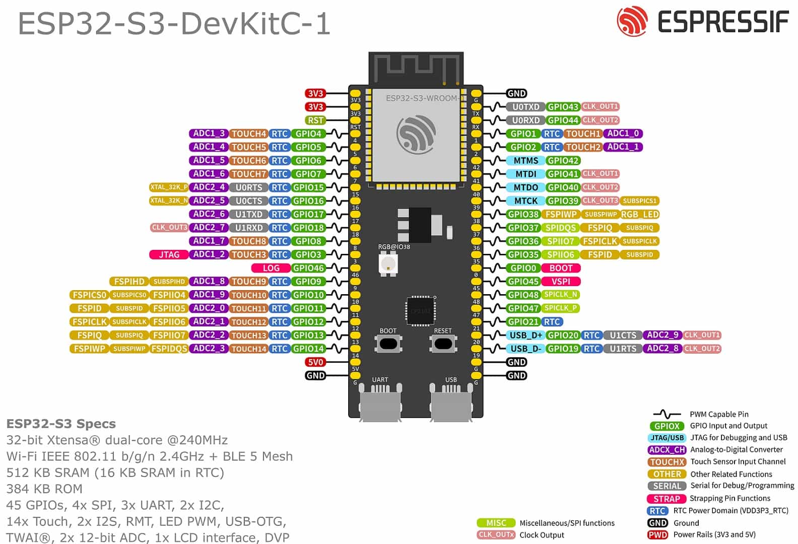
Key features:
- Microcontroller: ESP32-S3
- Clock Speed: Up to 240 MHz
- Wireless Connectivity: Wi-Fi 4 and BLE 5.0
- USB Type-C Port: Used for power, programming, and communication with our PC
- GPIO Pins: 45
- SRAM: 512 KB
- ROM: 384 KB
- Power Management: 5V to 3.3V voltage regulator
Raspberry Pi Pico
Pin layout:
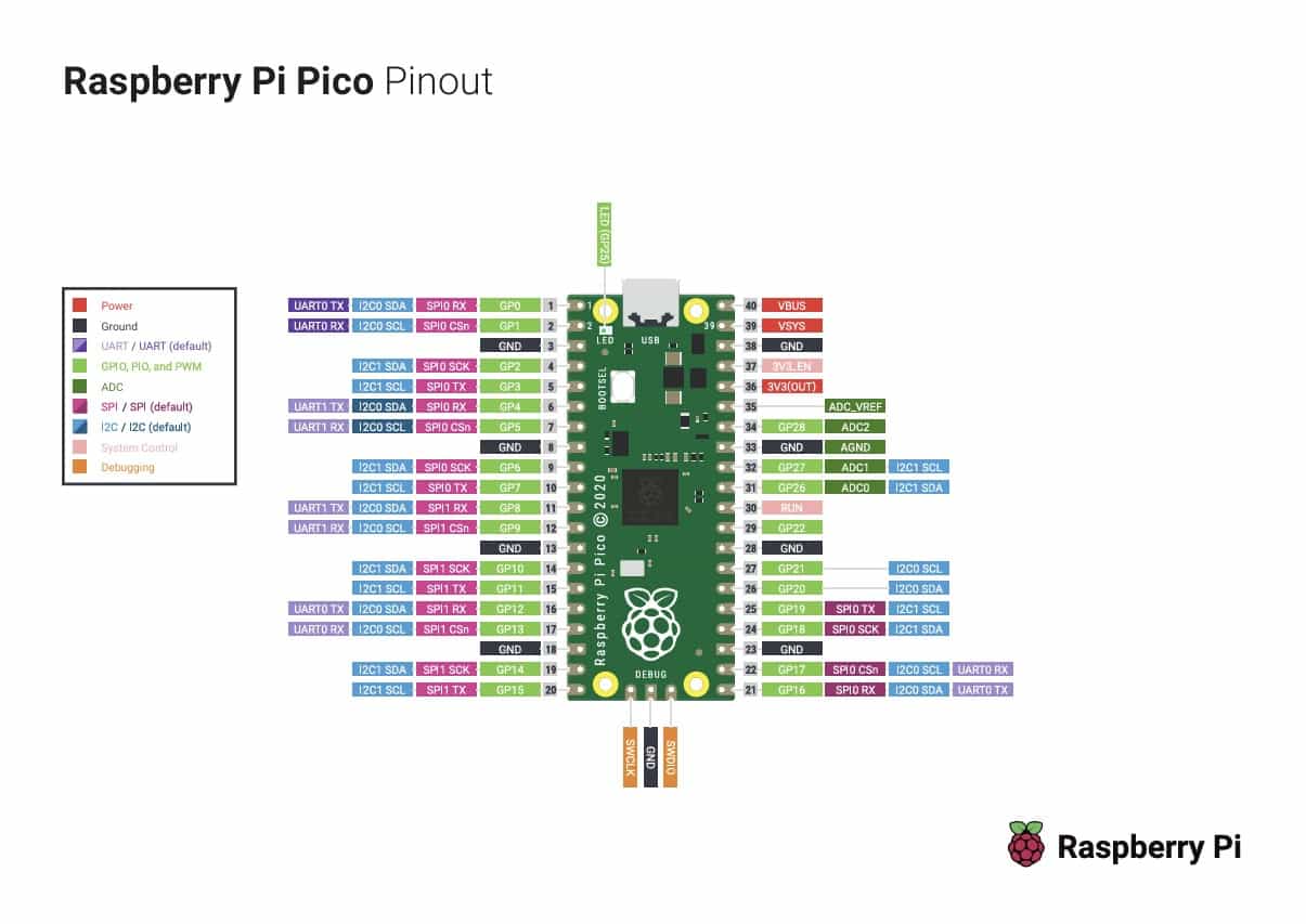
Key features:
- Microcontroller: RP2040
- Clock Speed: Up to 133 MHz
- SRAM: 264 KB
- Flash Storage: 2 MB
- GPIO Pins: 26
- USB Support: USB 1.1 with device and host support
- Power Management: Supports 1.8V to 5.5V input
Seeed Studio XIAO RP2040
Pin layout:
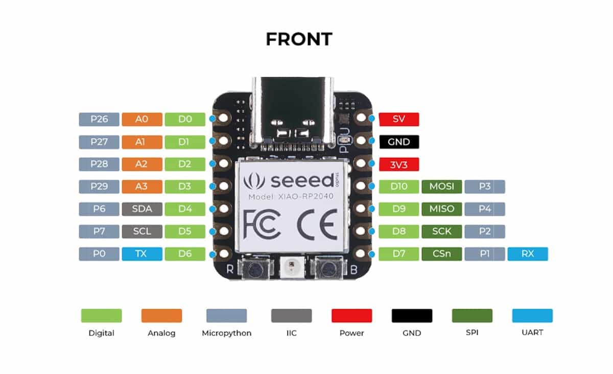
Key features:
- Microcontroller: RP2040
- Clock Speed: Up to 133 MHz
- SRAM: 264 KB
- Flash Storage: 2 MB
- GPIO Pins: 11
- USB Support: USB Type-C
- Power Management: 3.3V input
6. Embedded Programming
Embedded programming is the process that involves writing and integrating software into an embedded system. This type of code interacts directly with the hardware of our microcontroller and its stored in its memory, allowing it to operate independently.
The code written for a microcontroller must be tailored to said microcontroller's specific architecture, since we will be interacting directly with the hardware.
Another important aspect of embedded programming is the programming language that is used.
6.1 Programming Languages
A programming language is a written system of instructions that is used by computing devices to perform a variety of tasks. These languages vary greatly in structure and capabilities, and each has a specific set of rules that must be followed.
Programming languages vary in their level of interaction with hardware, which often correlates with their efficiency and complexity. Low-level languages, such as binary code and assembly, are the most efficient and provide direct hardware control but are also more complex. High-level languages, such as C++ and Python, are easier to write and read but require compilation or interpretation to be converted into machine code that the hardware can execute.
For this week's assignment, I will be working with high-level languages.
6.2 Compiled Language
A compiled language is a programming language that requires a translation into machine code previous to execution, by a type of software called a compiler. We write the code in a high-level language such as C++ and the compiler turns it into binary instructions, which are stored in a file that can be executed by our system.
The advantages of using a compiled language are that its execution is much faster and more efficient in terms of both power consumption and memory usage compared to an interpreted language. However, it has its downsides, which include the need to recompile the code after any modifications, potential system-specific compatibility issues, and generally higher complexity compared to an interpreted language.
Some examples include C, C++, Rust and Go. The compiled language that I chose to work with this week was C++.
6.3 Interpreted Language
An interpreted language is a programming language that requires continuous translation into machine code during execution by a special program called an interpreter. When we upload an interpreted program onto a system, we must also include the interpreter, which translates the code in real time, acting as a bridge between our program and the hardware.
Interpreted languages are easier to modify and debug since they do not require recompilation, they offer better cross-platform compatibility and are great for automating repetitive tasks. However, their main drawback is that the microcontroller must continuously run the interpreter, leading to higher power consumption and memory usage. This reduces our overall processing power, making interpreted languages less suitable for high performance applications than a compiled language.
The most well known examples are JavaScript and Python. The interpreted language that I chose to work with this week was Python.
7. Python
Python is a high-level, interpreted programming language known for its simplicity, readability, and versatility. It follows a relatively easy syntax that emphasizes clarity, making it popular for beginners such as myself. It comes with a vast standard library and is widely used in fields such as web development, data science, machine learning, automation, and embedded systems.
MicroPython is a variant of Python designed to run on microcontrollers and other environments with limited processing capabilities. It provides a subset of the standard Python 3 functionality with additional modules used for hardware control, such as the direct interaction with GPIO pins and the microcontrollers timing.
MicroPython is optimized to work with devices like the ESP32, and Raspberry Pi Pico, making it a popular choice for IoT applications, robotics, and embedded systems. Its lightweight nature allows developers to write Python scripts that execute directly on microcontrollers, reducing the need for complex low-level programming.
The main downside of Python and MicroPython, particularly in the context of microcontrollers, is performance and resource consumption. Since the language has to be interpreted as explained in section 6.3, the execution of our code is slower, it also uses more RAM.
However, while lacking in the raw speed and low-level control of C and C++, its ease of use, maintainability, and flexibility make it a strong choice for many embedded systems, particularly where rapid development is more critical than higher performance.
8. C++
C++ is a powerful and fast compiled programming language used in many fields like game development, embedded systems, operating systems, and high-performance applications. It is an extension of the C language, adding object-oriented programming and other features that help us organize and structure code better.
Because C++ is a compiled language, its code is translated directly into machine instructions, making it significantly faster than interpreted languages like Python. This speed and efficiency make it ideal for applications where we need higher performance, such as real-time systems, robotics, and graphics engines.
One of C++'s biggest strengths is its ability to work closely with hardware. Unlike Python, which is very limited in low-level programming, C++ gives us direct control over memory and processing power. This makes it an ideal choice for embedded systems, microcontrollers, and high-performance applications.
However, C++ is also more complex and challenging to learn compared to beginner friendly languages like Python. Its syntax can be difficult for beginners, and it requires a deeper understanding of the field. Additionally, because C++ is a compiled language, the process of writing, debugging, and running programs takes longer compared to interpreted languages, where changes can be tested instantly.
Despite these challenges, C++ remains one of the most widely used programming languages due to its power, efficiency, and versatility. Its capability of handling complex and high speed tasks has made it an essential tool in fields where performance matters most.
9. Raspberry Pi Pico, Python Simulation
For this week's assignment I made two simulations of a motor control system, using the Wokwi online platform.
The first simulation was made using a Raspberry Pi Pico development board equipped with an RP2040 microcontroller and using the Python programming language.
Let's go over the steps:
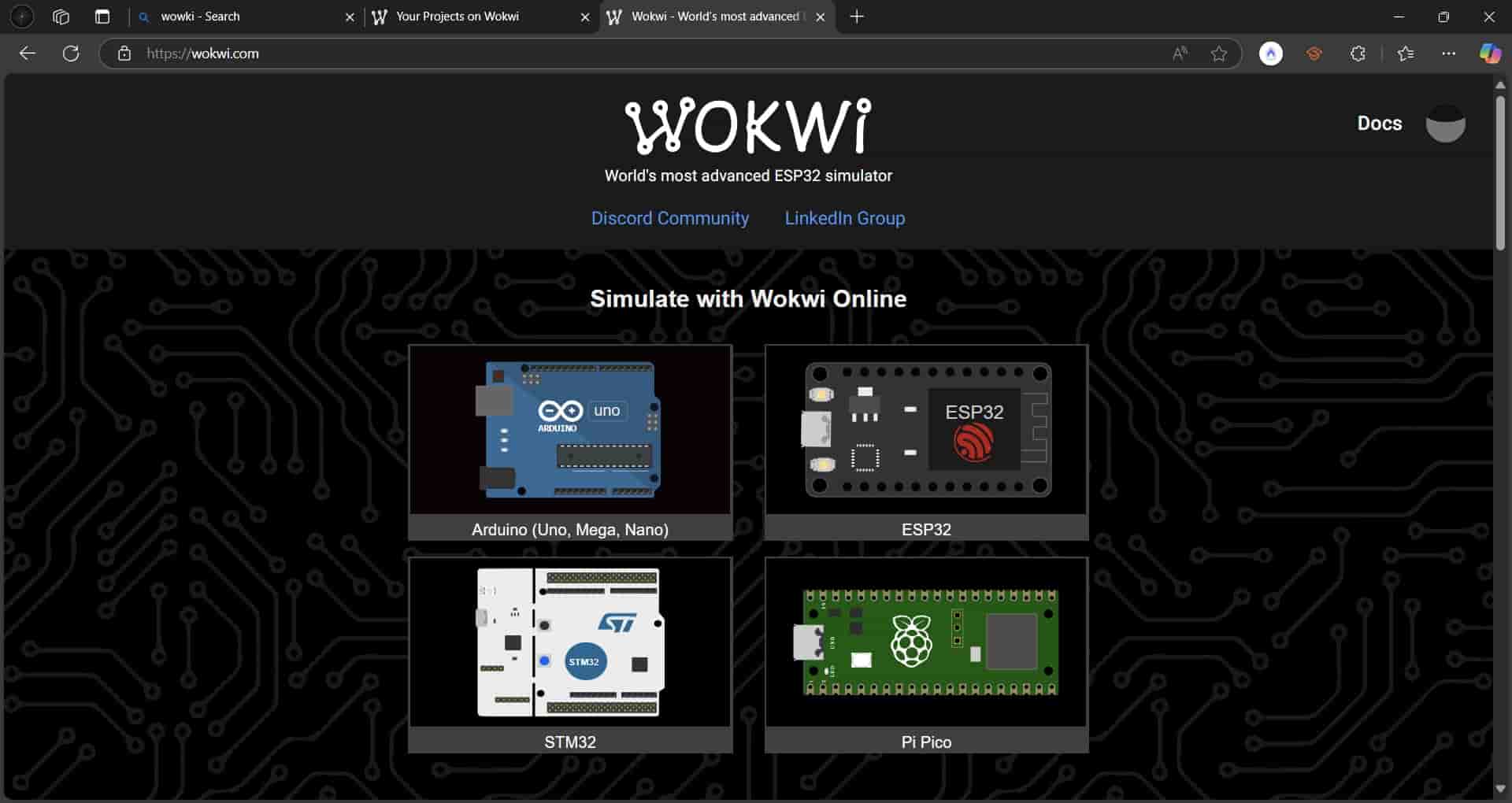
1. Getting started with Wokwi
We search for Wokwi in our web browser and go into the website. In order to be able to save our projects, we have to create an account with an email.
Once our account is set up, we can begin with our new project.
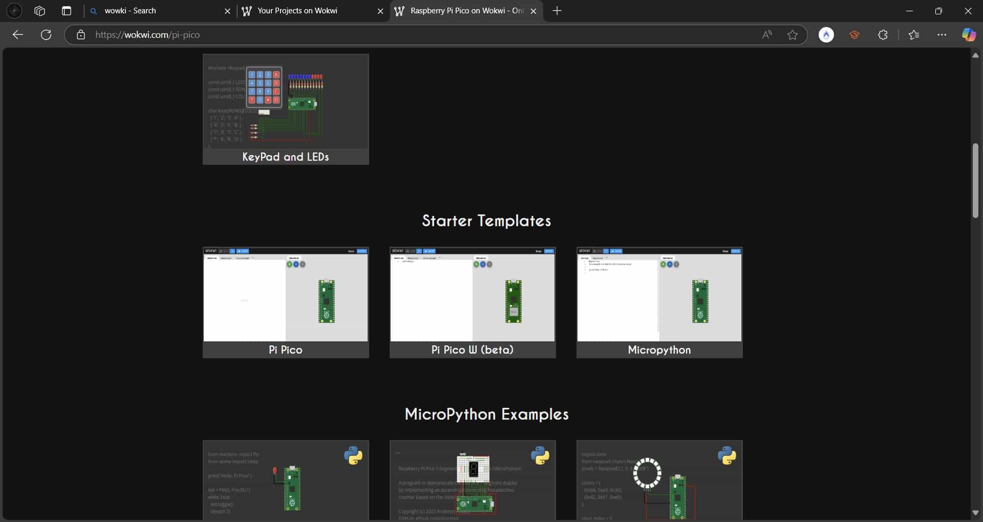
2. New Project
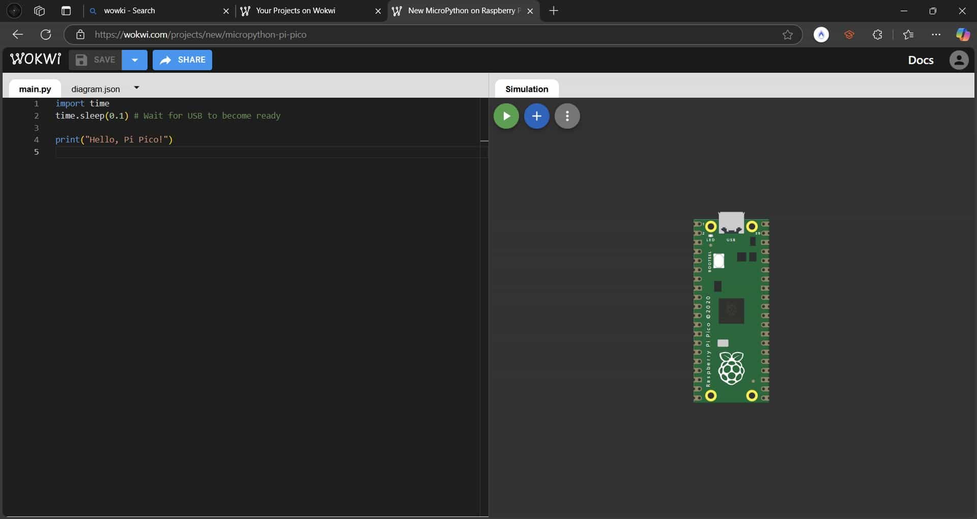
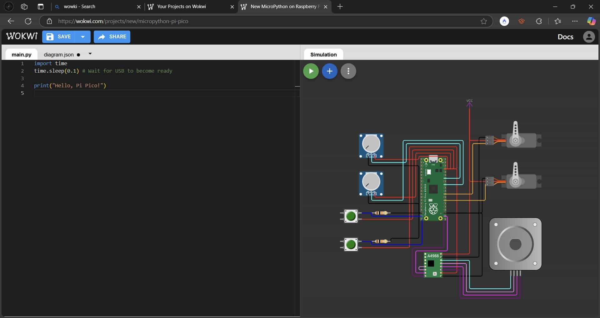
In the main menu we can see the options for the family of dev board that we can simulate, in my case I select the Pi Pico family and then the MycroPython starter template.
We can see that the screen is divided in two, on the left side we will write our code and on the right side we will build our system.
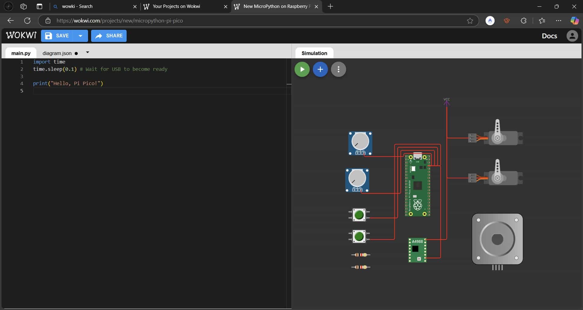
3. Insert Components
Once we create our new project, we have to insert all of the components that will be part of our system, we do this by pressing the blue circle with a +, and a list of components will be display.
We insert all the components that we want and arrange them in the correct position.

In my case I used:
- 1 VCC Output
- 1 A4988 Stepper motor driver
- 1 Bipolar Stepper motor
- 2 Servo motors
- 2 Potentiometers
- 2 Push Buttons
- 2 Resistors
4. Wiring components
We begin wiring our components, for this I recommend establishing a color code in order to avoid confusion. When we select a component's pin, a wire will be generated and the dev board will display which GPIO pins are compatible with that particular input.
I began by wiring the power with red wires;
Ground in black;
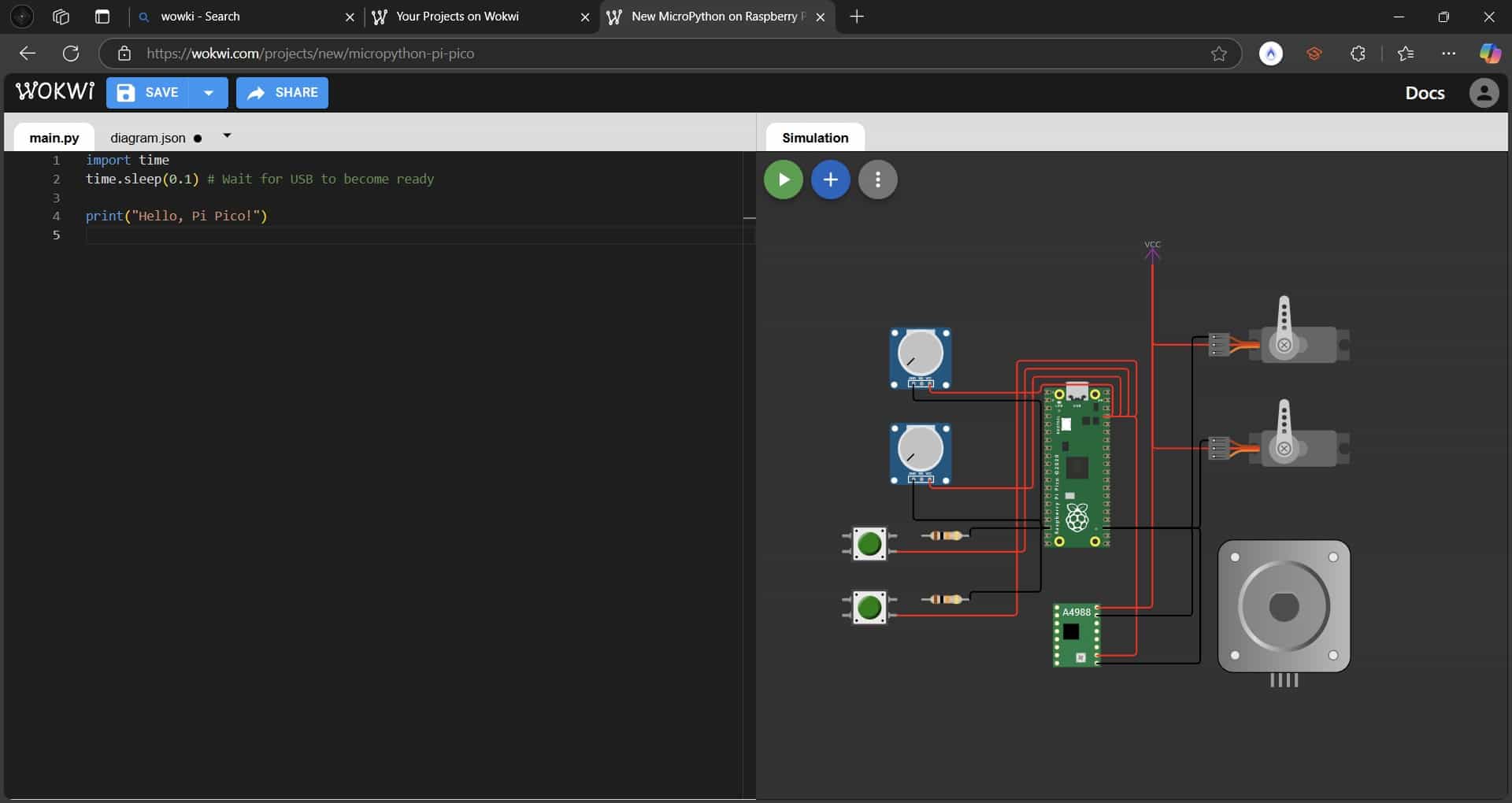
Analog inputs from our potentiometers in cyan, it is worth noting that not all GPIO pins are compatible with these types of inputs, the Pi Pico's ADC pins are the GP26, 27 and 28;
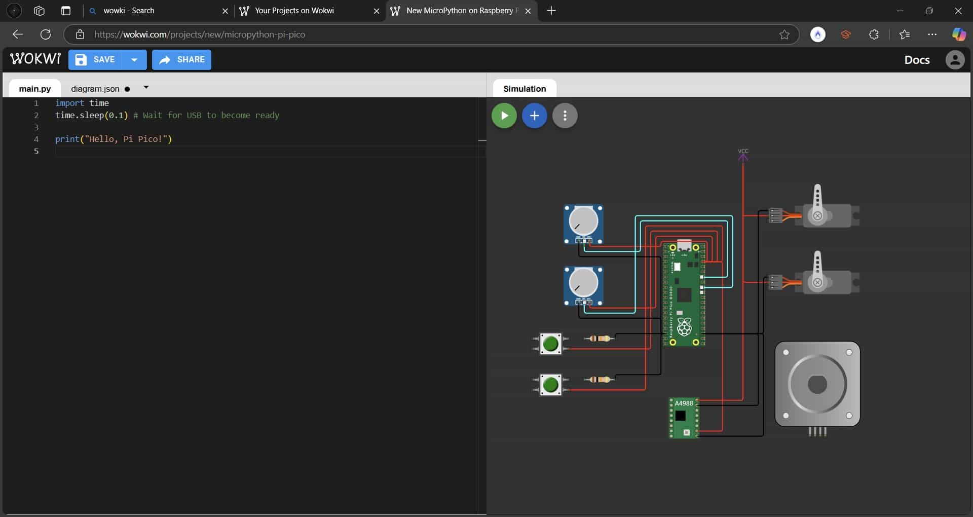
Digital inputs from our buttons in blue;
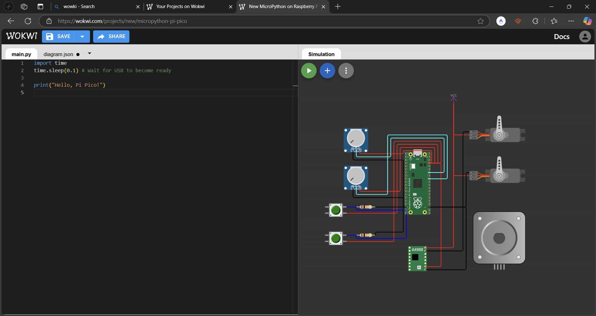
And finally our outputs, where I used orange for the servos, purple, pink and cyan for the stepper motor and its driver;
5. Programming
We will be using MicroPython to write our code. MicroPython is a variant of the Python language, optimized for microcontrollers, they share the same syntax but MicroPython has specific modules and lacks some of the Python libraries.
Here is the coding process that I followed:
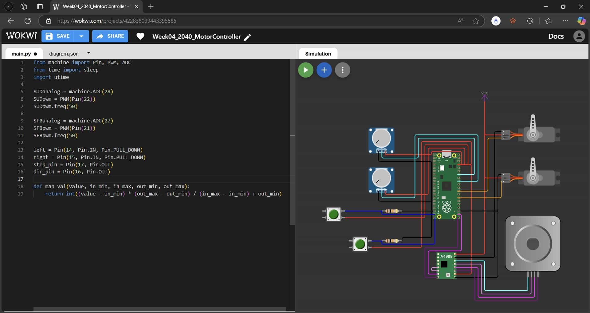
- Import libraries
Our first lines of code are usted to import the necessary libraries, which include prewritten functions.
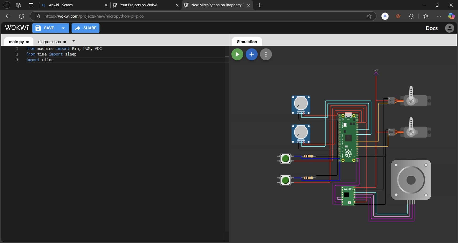
- machine - A built-in MicroPython module used to interface with hardware components like GPIO pins, PWM, and ADC.
- Pin - Controls GPIO pins.
- PWM - Generates Pulse Width Modulation (PWM) signals for servos or motors.
- ADC - Reads analog values from sensors.
- time.sleep() and utime.sleep() - Allow us to delay the execution of the program, which is useul for stability.
- Analog Inputs and PWM Outputs
These lines of code configure our analog input pins and pulse width modulation output pins, these will be in charge of our servo motors.
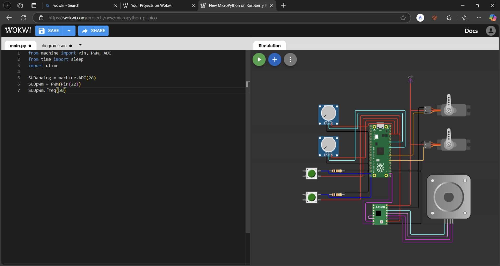
- SUDanalog = machine.ADC(28) - Sets up GPIO 28 as an analog input.
- SUDpwm = PWM(Pin(22)) - Sets up GPIO 22 as a PWM output.
- SUDpwm.freq(50) - Sets the PWM frequency to 50 Hz.
- SFBanalog = machine.ADC(27) - Sets up GPIO 27 as another analog input.
- SFBpwm = PWM(Pin(21)) - Sets up GPIO 21 as another PWM output.
- SFBpwm.freq(50) - Sets the PWM frequency to 50 Hz.
- Stepper motor control pins
These lines of code configure the pins that will be the inputs and outputs controlling our stepper motor.
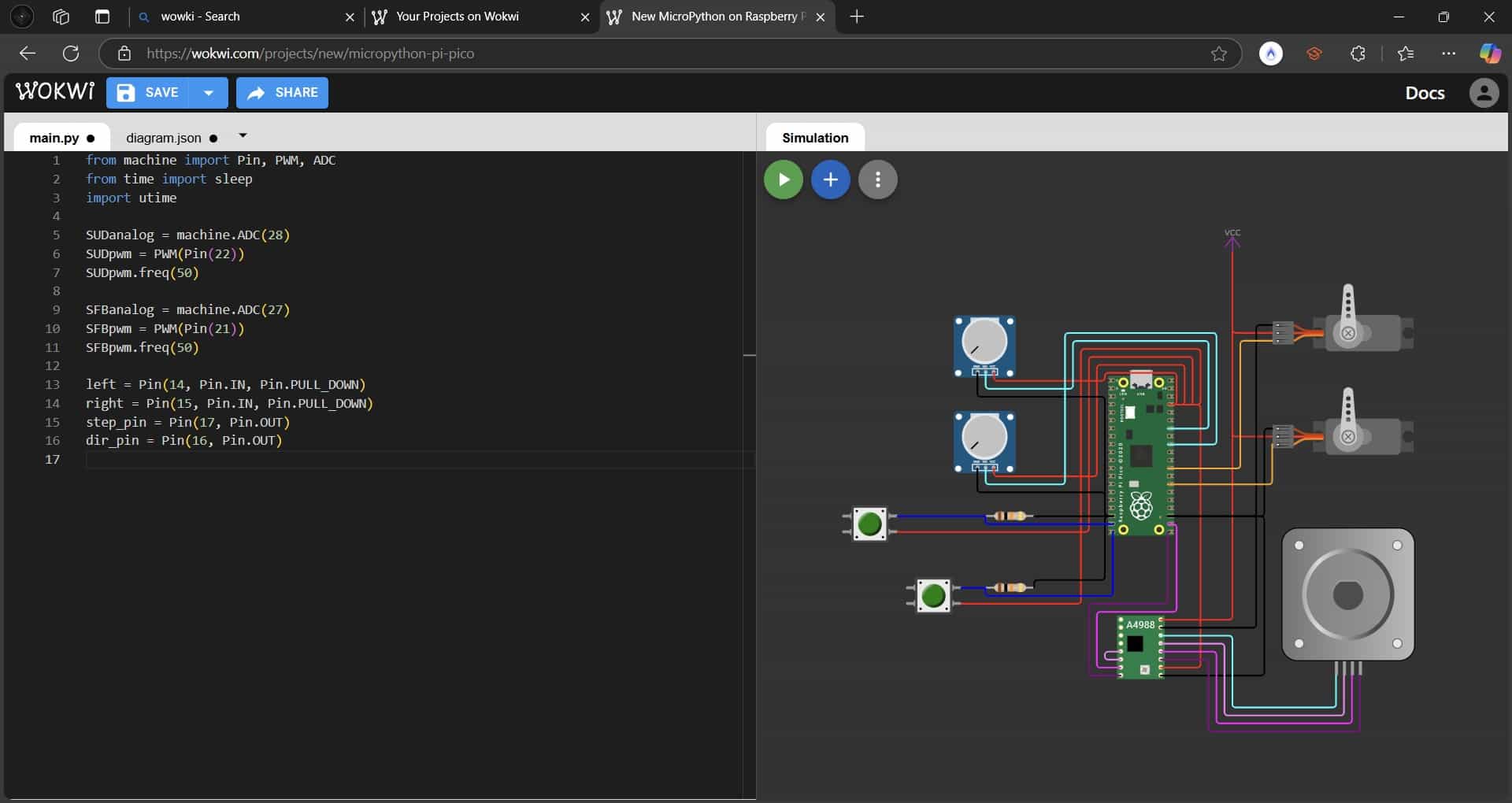
- left (GPIO 14) - Connected to the push button that will move our motor counterclockwise.
- right (GPIO 15) - Connected to the other push button, which will move the motor in a clockwise direction.
- Pin.PULL_DOWN - Ensures the pin defaults to LOW or 0 unless we press the buttons.
- Mapping Function for ADC to PWM Conversion
To effectively use our potentiometers, we have to use a function that will turn the analog inputs into PWM signals.
 This function converts an ADC reading, ranging from 0 to 65535, into a PWM duty cycle which ranges from 2000 to 8000.
This function uses this mathematical formula:
This function converts an ADC reading, ranging from 0 to 65535, into a PWM duty cycle which ranges from 2000 to 8000.
This function uses this mathematical formula:
- Stepper Motor Movement Function
Our stepper motor works in conjunction with our A4988 driver, which has two digital inputs, one for direction and one for movement. This function determines that the motor while move only when we press one of the buttons, and will stop when we stop pressing it.
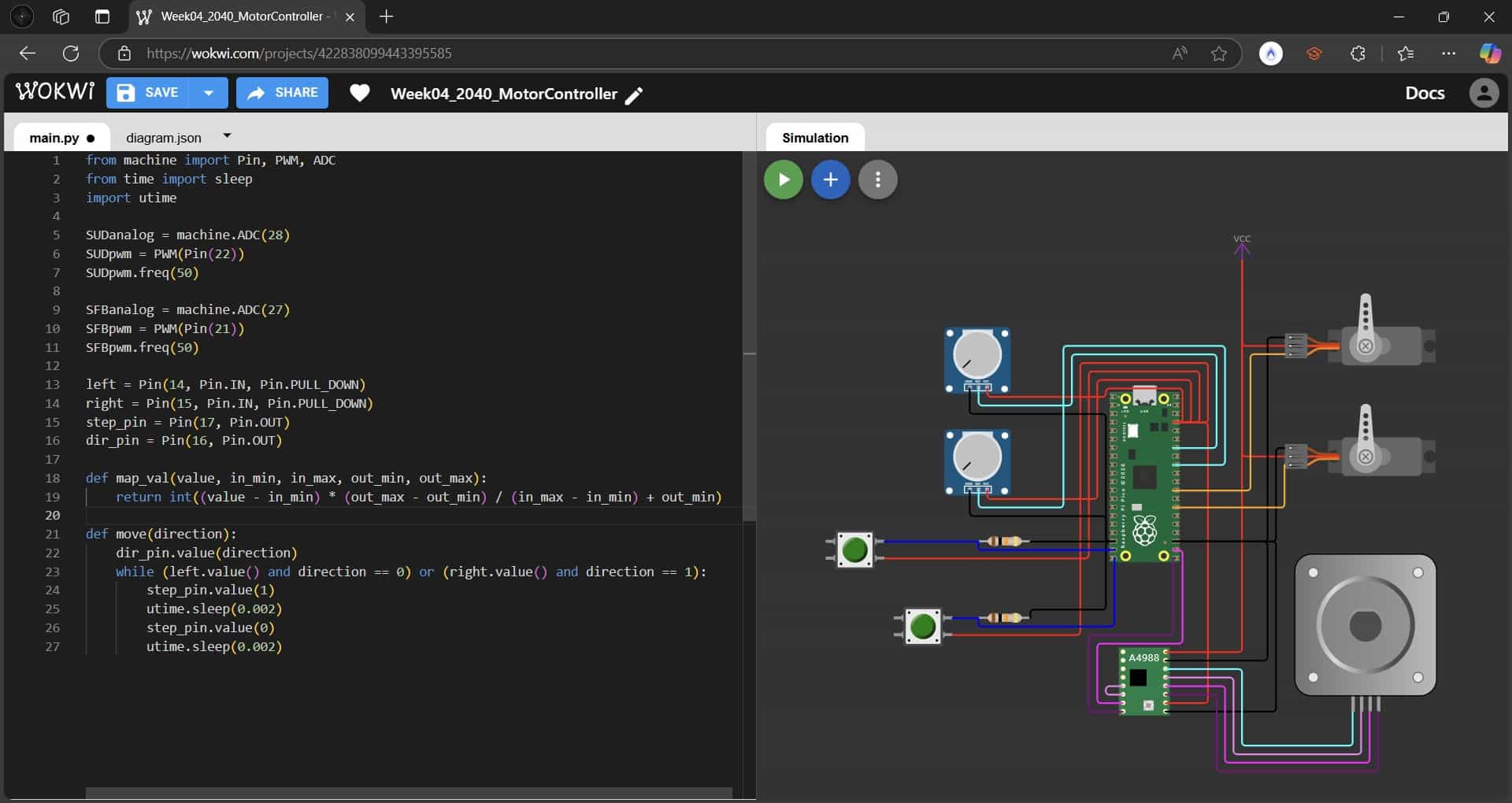
- dir_pin.value(direction) - Sets the direction of movement.
- while loop - Moves the motor until a limit switch is released.
- step_pin.value(1) - Sends a HIGH pulse to move the stepper motor forward.
- utime.sleep(0.002) - Short delay (2ms) between pulses to control speed.
- Main Loop
The main loop is a set of instructions that are executed continuously.
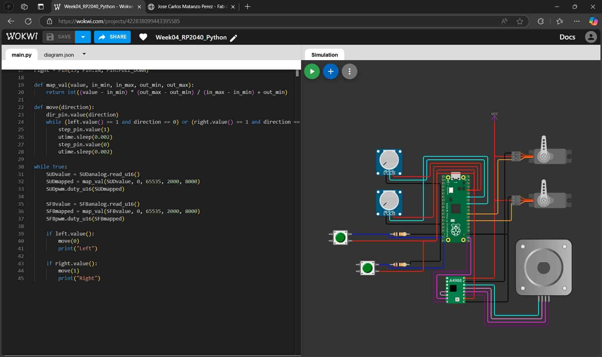 Our main loop is in charge of:
- Reading the ADC values from SUDanalog from GPIO 28 and SFBanalog from GPIO 27.
- Mapping the ADC values to PWM duty cycles through SUDmapped and SFBmapped.
- Setting the PWM duty cycles to control servo motors with duty_u16().
- Checks the values of our button inputs with left.value() and right.value():
- If the left button is pressed, calls move(0), moving the motor counterclockwise.
- If the right button is pressed, calls move(1), moving the motor clockwise.
- Prints "Left" or "Right" when the motor moves, displaying a simple form of communication.
6. Testing the simulation
Success!
10. ESP32-S3-DevKit-C1, C++ Simulation
The second simulation was a replica of the same motor control system, but using an ESP32-S3-DevKit-C1 development board and code written in the C++ language.
Due to my unfamiliarity with the simulator, I wasn't able to properly integrate libraries for this simulation, so I had to take a different aproach.
I followed this process:
1. New Project
We go to the main menu and select the ESP32 option, we then choose the ESP32-S3 template.
2. Insert components
We insert the same components that we used in the first simulation.
3. Wiring
We make the necessary connections between the components, which are in principle the exact same as the ones in the first simulation, only accounting for the differences in the location and functionality of the ESP32-S3's GPIO pins.
4. Programming
- Inputs and Outputs
First, we define the pin numbers for our inputs, the potentiometers and buttons, and our outputs, to control the servos and stepper motor.
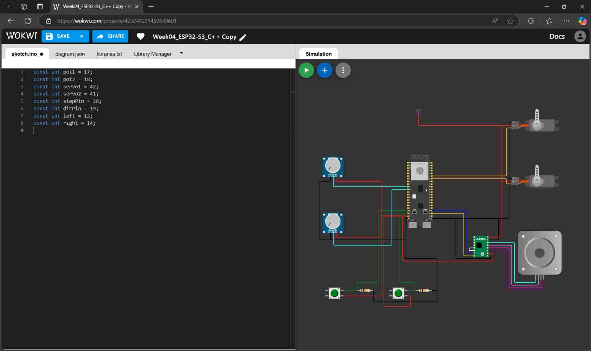
- const int pot1 = 17; & cons int pot2; - These read analog input values to control the servo motor's positions.
- const int servo1 = 42; & cons int pot2; - Outputs PWM signals to the servos.
- const int stepPin = 20; - Sends step pulses to the stepper motor driver.
- const int dirPin = 19; - Outputs the direction of the stepper motor's movement.
- const int leftButton = 13; & const int rightButton = 14; - These are the inputs that determine when and in which direction the stepper mottor should move.
- Servo Control Function
This function generates a PWM signal to control the servo's position based on the given angle.
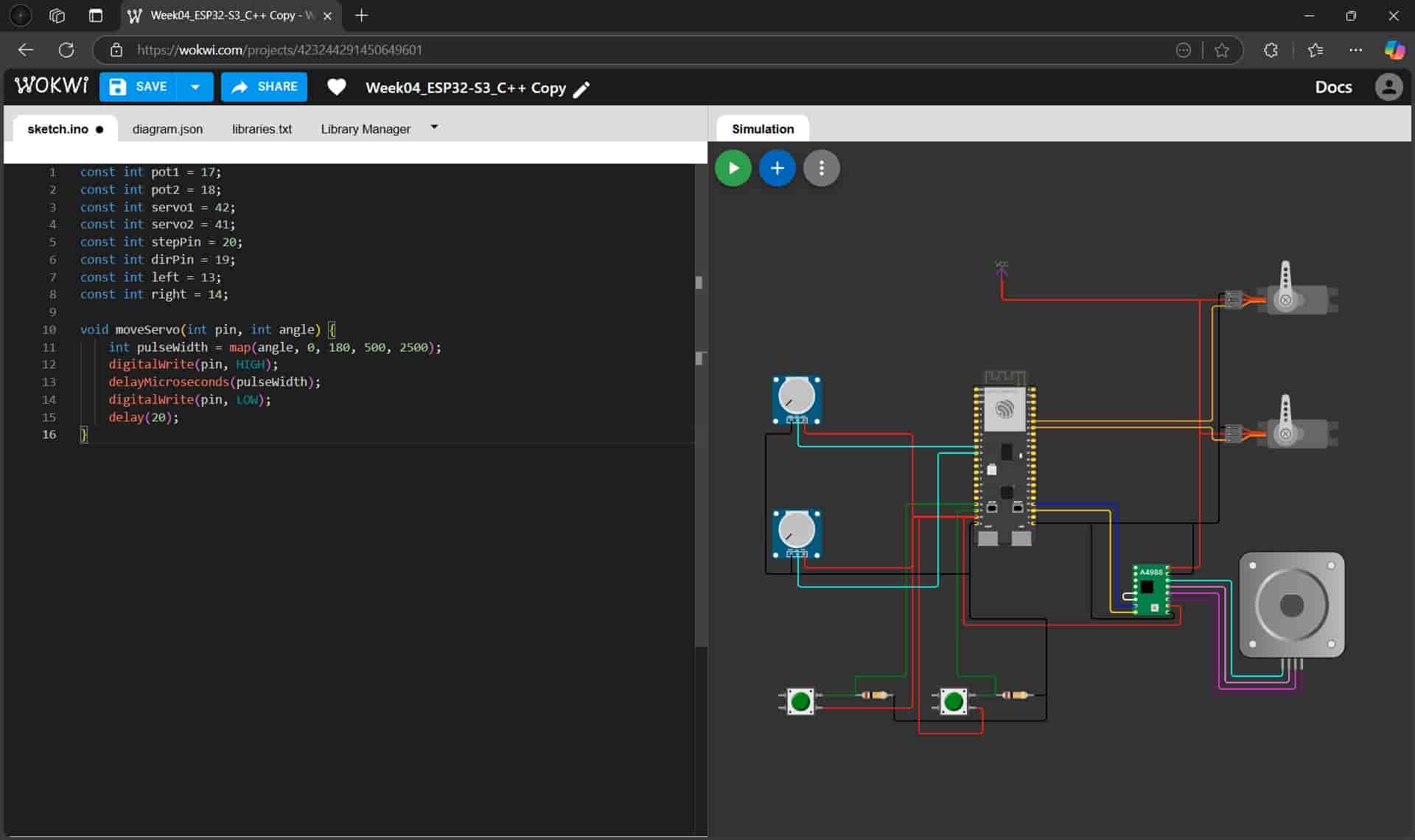
- void moveServo(int pin, int angle); - Function to generate PWM signals for the servo motor.
- map(angle, 0, 180, 500, 2500); - Converts the angle, ranging from 0 to 180° into a PWM pulse width, ranging from 500 to 2500µs).
- digitalWrite(pin, HIGH); - Starts the PWM pulse.
- delayMicroseconds(pulseWidth); - Holds the pulse HIGH for the required duration.
- digitalWrite(pin, LOW); - Ends the PWM pulse.
- delay(20); - Ensures a 50Hz refresh rate for servo operation.
- Stepper Motor Function
This function moves our stepper motor ten steps in the given direction.
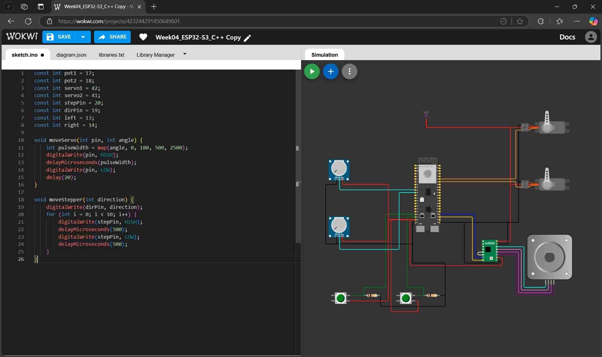
- void moveStepper(int direction); - Moves the stepper motor in the specified direction.
- digitalWrite(dirPin, direction); - Sets the rotation direction.
- for (int i = 0; i < 10; i++); - Moves 10 steps.
- digitalWrite(stepPin, HIGH); - Sends a pulse to the stepper driver.
- delayMicroseconds(500); - Controls the speed of the stepper motor.
- digitalWrite(stepPin, LOW); - Ends the step pulse.
- Setup Function
Configues all the necessary pins.
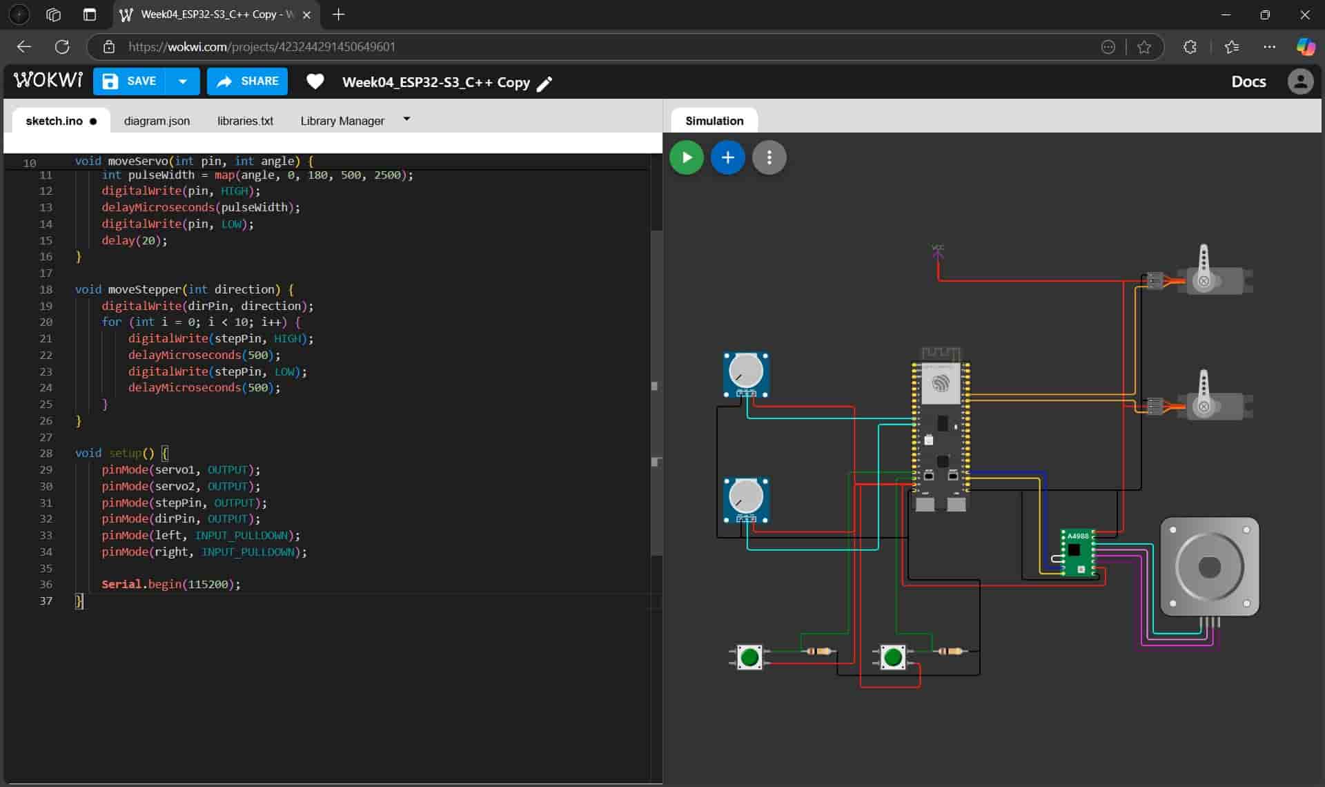
- void setup(); - Initializes pin configurations.
- pinMode(servo1, OUTPUT); & pinMode(servo2, OUTPUT); - Sets the pins that will output the PWM signals for our servos.
- pinMode(stepPin, OUTPUT); & pinMode(dirPin, OUTPUT); - Sets the pins that will be the outputs to control our stepper motor.
- pinMode(leftButton, INPUT_PULLDOWN); & pinMode(rightButton, INPUT_PULLDOWN); - Configures buttons with internal pulldown resistors.
- Serial.begin(115200); - Initializes serial communication with our serial monitor, at a baud rate of 115200.
- Main Loop
Equal to the first simulation, the main loop is continuously executed.
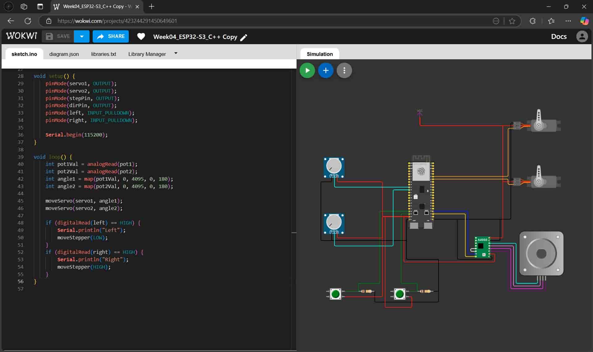
- void loop(); - Continuously runs to control the servos and stepper motor.
- int pot1Val = analogRead(pot1); & int pot2Val = analogRead(pot2); - Reads potentiometer values (0-4095).
- int angle1 = map(pot1Val, 0, 4095, 0, 180); & int angle2 = map(pot2Val, 0, 4095, 0, 180); - Converts the ADC values to servo angles.
- moveServo(servo1, angle1); & moveServo(servo2, angle2); - Moves servos to the desired angles.
- if (digitalRead(leftButton) == HIGH); - Checks if the left button is pressed.
- Serial.println("Left"); - Prints "Left" on our serial monitor when we press the left button.
- moveStepper(LOW); - Moves the stepper motor left.
- if (digitalRead(rightButton) == HIGH); - Checks if the right button is pressed.
- Serial.println("Right"); - Prints "Right" on our serial monitor when we press the right button.
- moveStepper(HIGH); - Moves the stepper motor right.
6. Testing the simulation
Another great success!
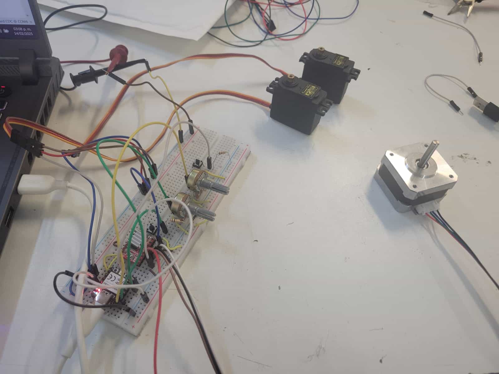
11. Physical Circuit
This system was replicated using physical components, sadly to no success.
I replicated the system using a XIAO-RP2040 development board and all the components used in the simulation. I used 10 kΩ resistors for the buttons and 5 kΩ Potentiometers, I separated the power for my control electronics and my motors, using the 3.3v output of the XIAO and 5A with 1 A for my motors.
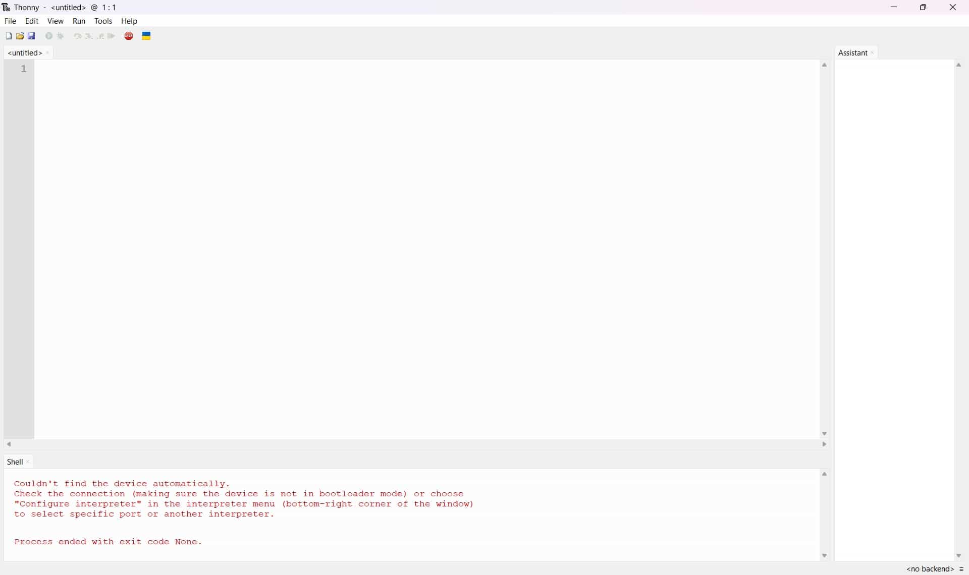
After checking my connections I began to work with the XIAO, which was more difficult than expected.
- I opened the Thonny IDE in my computer, I went to the tools section in the top of the screen, selected the options and then I opened the interpreter menu and selected the MicroPython (Raspberry PiPico) interpretrer.
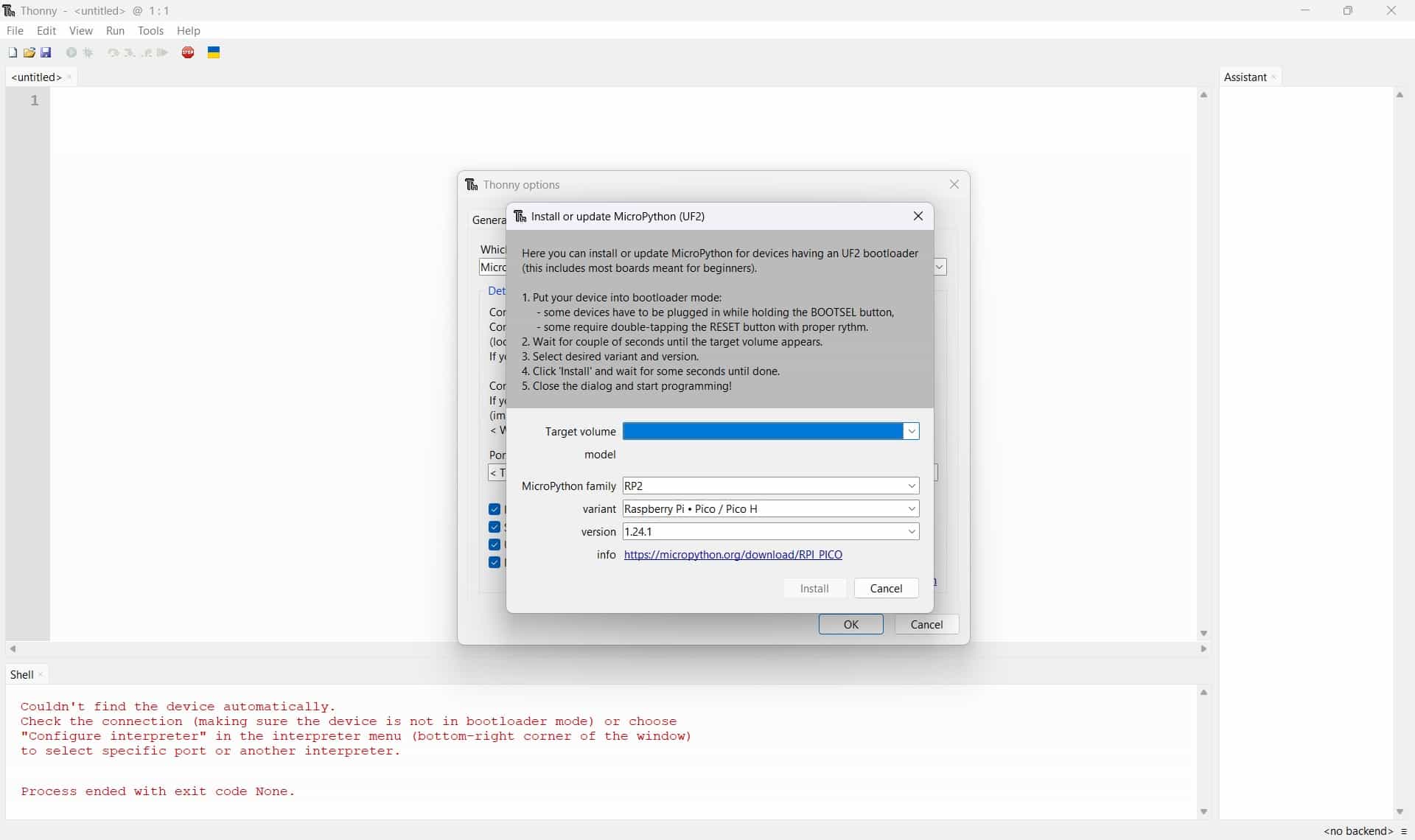
- I connected the XIAO to my computer through the USB cable, then I pressed and held the R button, followed by the B button, then I released the buttons in the same order.
- A new folder was generated in my computer, which I copied into the Install MycroPython menu, I also inputed the MicroPython family and variant. With this the XIAO should be fully configured.
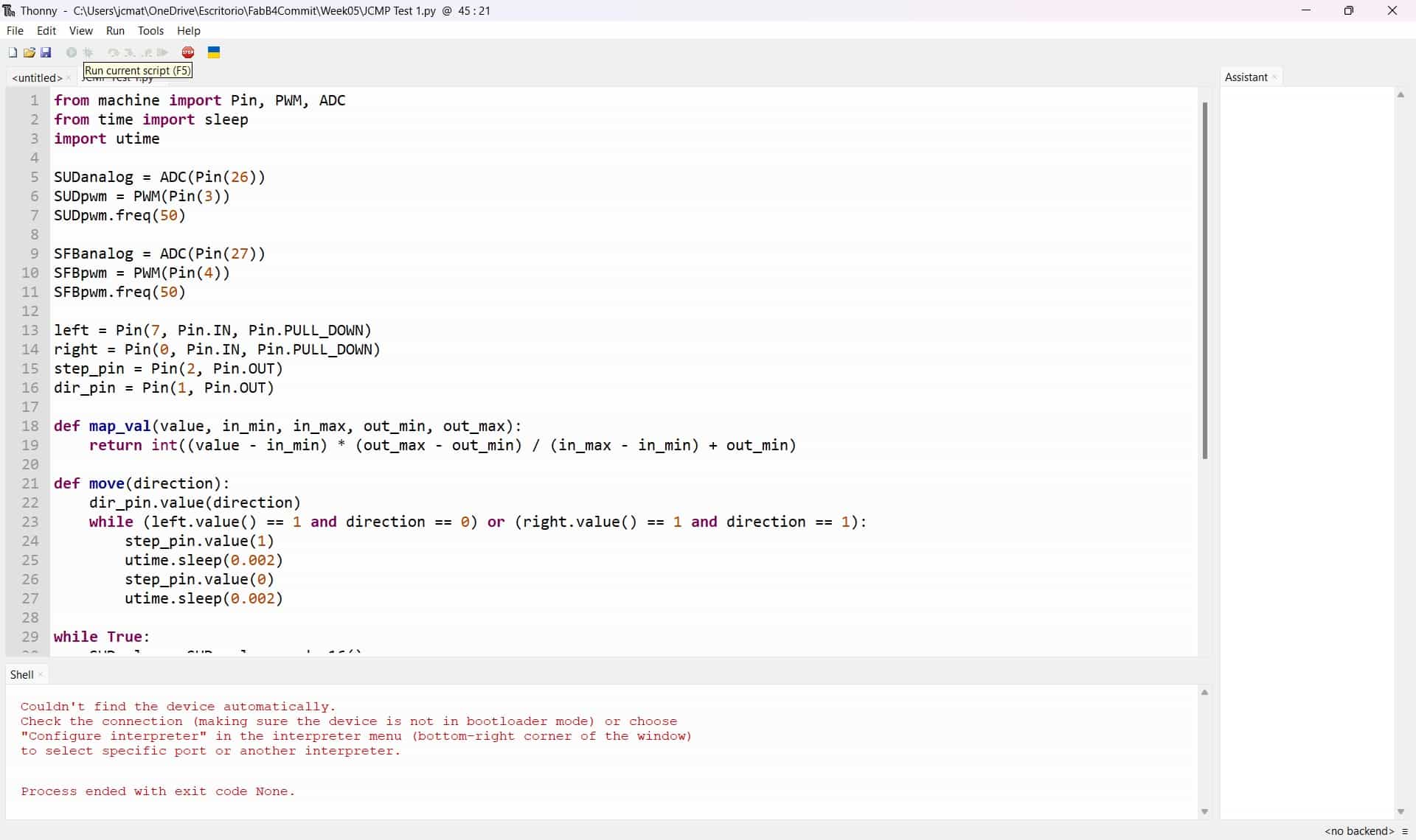
- I copied and pasted the code from my Raspberry Pi Pico Python simulation and corrected the pins written in the code to correspond to the ones in my physical connections.
- This is when I tried to run the program, but something was off, the ADC inputs weren't changing when I moved the potentiometers, the buttons weren't doing anything either.
- I asked my electronics teacher if my connections looked off, but he said they looked correct, then I asked my local intructor for advice, at which point I was told that my pins had to be configured based on the XIAO's GPIO pin layout, which isn't the one I followed.
- After correcting this, I tried again, but to no avail. At this point I had to stop the tests due to time constraints and to allow other classmates to use the XIAO.
12. Comments and Recommendations
The simulated environments are very useful for designing our circuit and testing our code, however, any physical versions may be affected by a variety of variables that cannot be accounted for in the simulations, such as faulty components, connections or the effects of having an excess of voltage.
Due to the physical circuit being a failure, I did not think it necessary to do extensive documentation, which I now know was a mistake, even failures should be documented, because they can be crucial in the development and success of our project.
13. Learning Outcomes
This week I learned how to use the Wokwi online platform to simulate a motor control system using two different microcontrollers and programming languages.
Files
Group Assignment
Useful links
- ESP32-S3 Datasheet
- ESP32-S3-DevKit-C1 documentation
- RP2040 Datasheet
- Raspberry Pi Pico documentation
- XIAO RP2040 documentation
- Wokwi website