8. Electronics production
Eight week and cutting again
This week we manufacture the pcb we made 2 weeks ago. In my case I decided to create a new pcb because I wanted to test the components I’m planning to use for my final project.
Here you can see what we did in our group assignment. Group Assignment
I started by making the new PCB in KiCad, this will have 2 H bridge, 2 capacitors, pin headers, a switch and will be power by xiao rp2040.
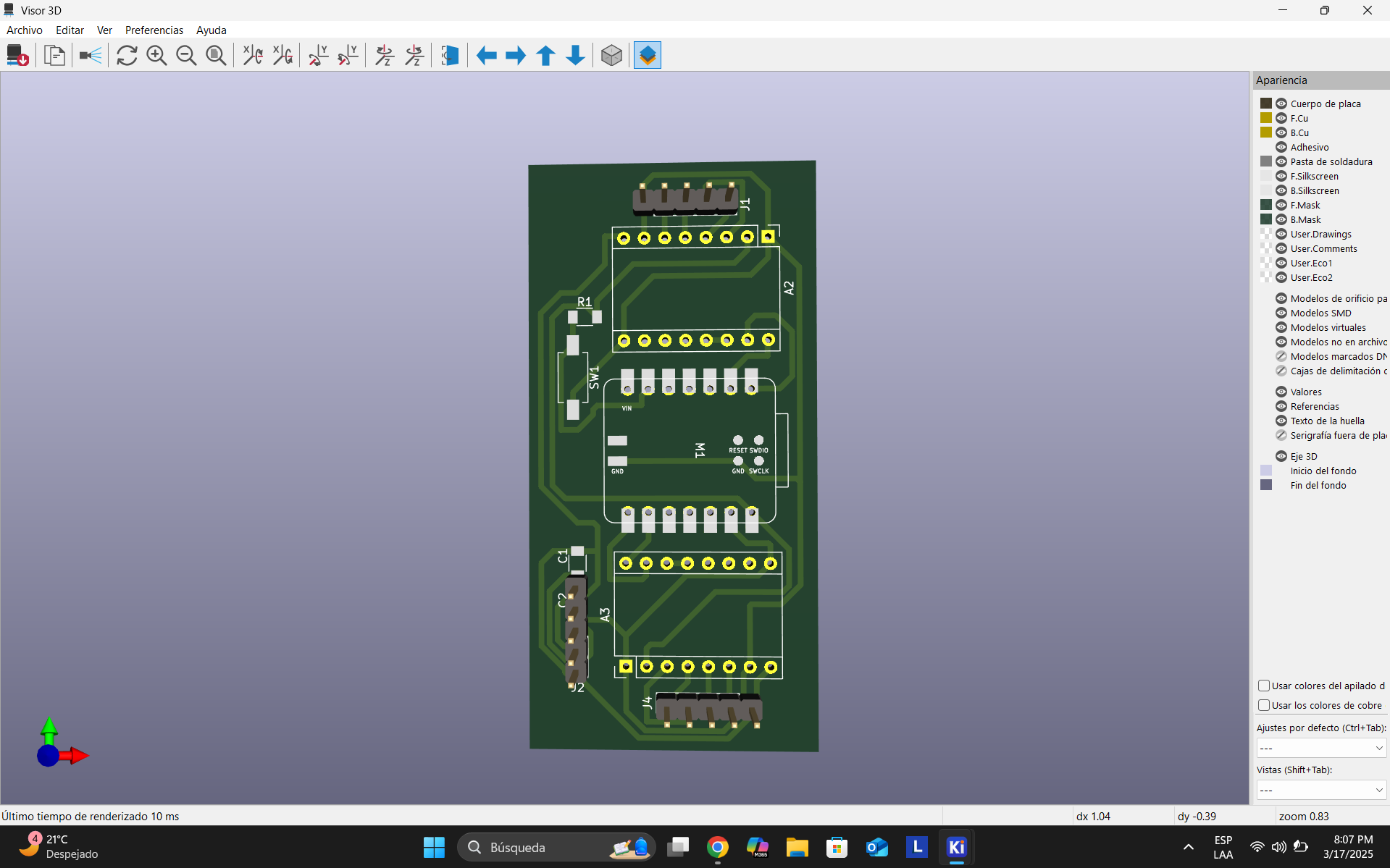
I used 3 layers. The first one is the cupper one that will have my traces for all the connections, the second one is a custom made by me that will mark where the holes for the drilling be, and the last one is the edge cut. This will make cuts for the perimeter of the pcb.
Now that the design is made, we will be using the software Mods CE, it is open source, and you don’t have to download it.
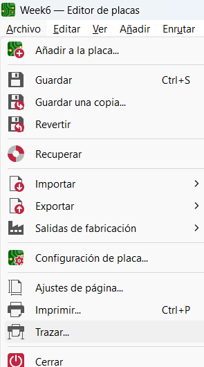
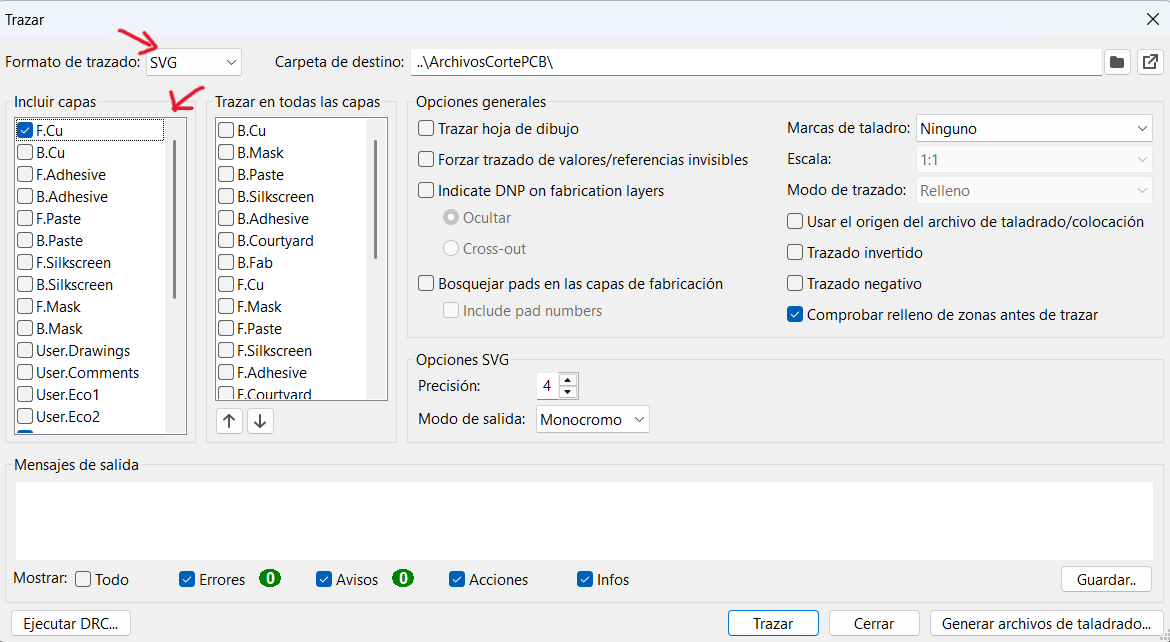
To prepare the file we must save each layer as SVG file. To do so we must search the trace option in files (Top left corner) and select the layers individually to save as SVG.
Here you can select where to save the SVG and which layers to save.
Once all the SVG’s are saved open the Mods CE and right click anywhere on the screen. You will see the next menus:
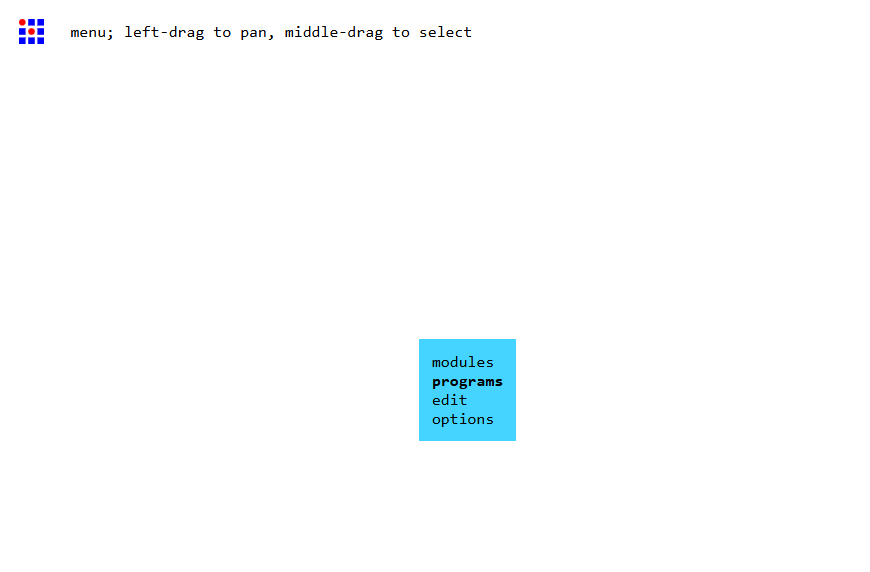
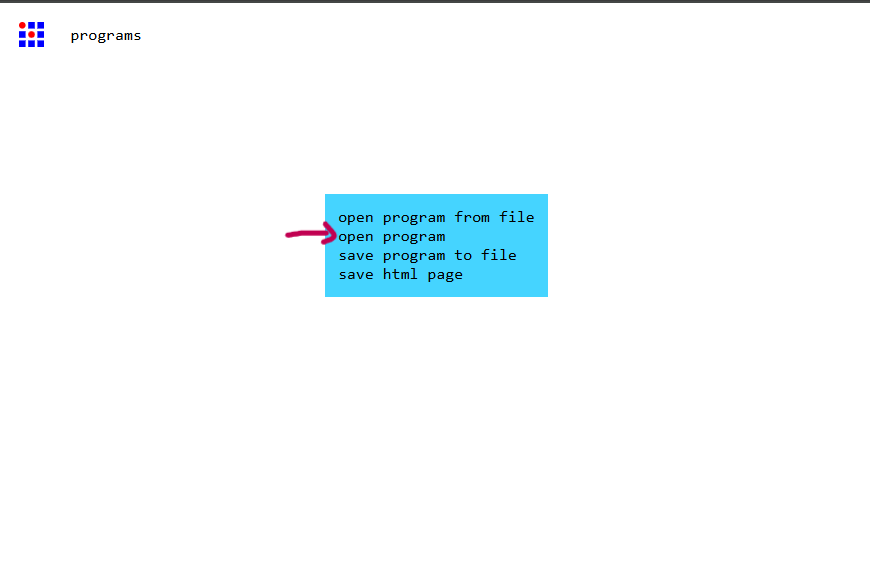
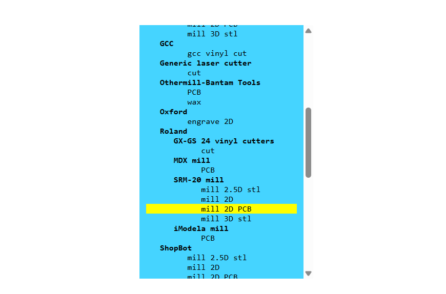
The program to select must be the Mill 2D PCB in the section Rolland SRM-20 Mill. Once selected we must locate the: import SVG and then upload the first layer, it its recommended to start with the drilling, then the traces and lastly the edge cut.
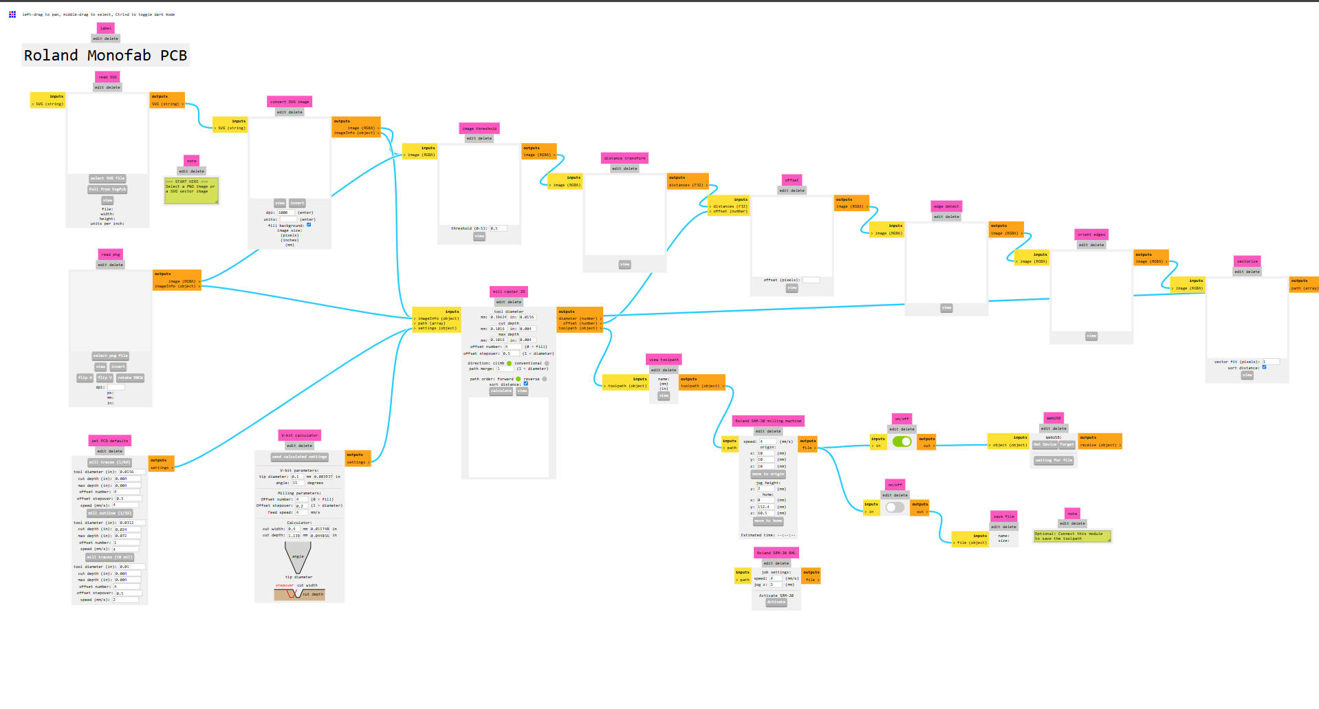
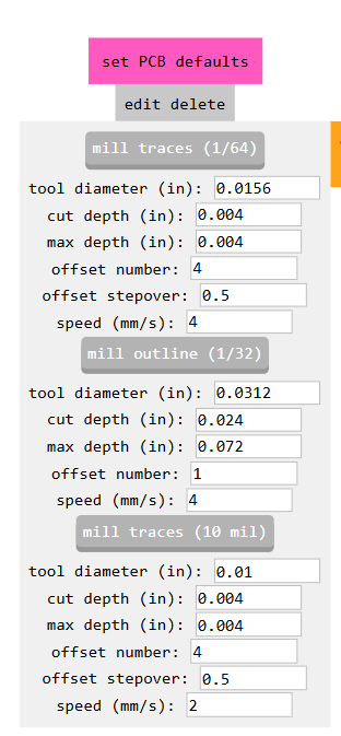
With the Edge cut and the Drill we must locate the section “Set PCB default” and select the option “mill outline 1/32” Then locate the section mill raster 2d and change the tool diameter. In my case I used it for drilling .8mm and for the edge cut at 1.8mm. Locate now: Rolland SRM-20 Milling machine. And change the speed for all 3 layers to 2mm/s and change the 3 origins to 0, then click move to origin. Lastly turn on the “on/off” section. Now in the Mill raster 2D click “calculate” it will give you a preview of the cutting edges and download the file to cut
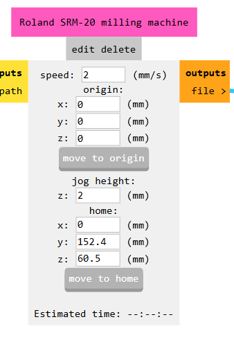
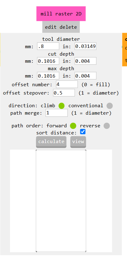
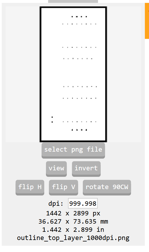
cutting with SRM-20
To cut, we’ve being provided the software and the SRM-20 driver. First install the driver, which is really easy and the then software (You won’t have any issues with any installation)
Then, turned on the machine and verified that it was properly connected to my laptop.
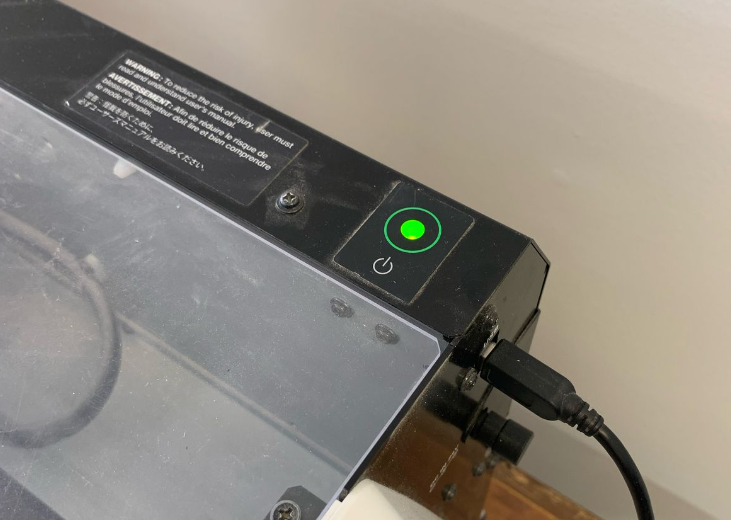
I used a sacrificial bed made of MDF to protect the milling surface, then places the PCB on top of it with double sided tape.
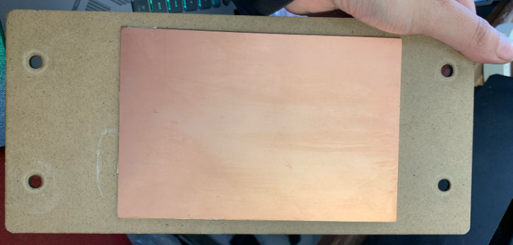
After that, I secured the bed inside the machine and adjusted it using screws.
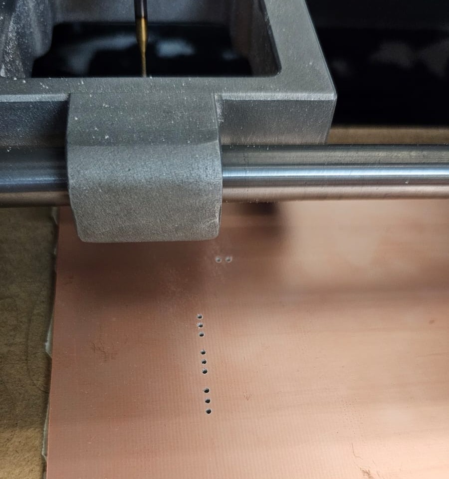
he first tool was the drilling tool with a diameter of 0.8 mm, used for holes and cutting the PCB outline.
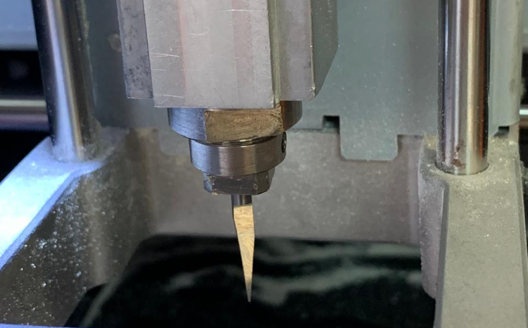
The second tool was a V-shaped engraving tool, used for the PCB traces.
Before milling, I needed to calibrate the machine axes:
First, I calibrated the X and Y axes at the lower-left corner of the PCB.Then the Z-axis

For large movements, I selected the “x10” option.
For small, precise adjustments, the “X1” option.
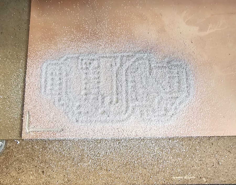
You have to select each file for each process. Starting with the holes, then the traces and then the outline of the PCB. This is how it looked after the traces were made
Soldering Basics
1. Gather Tools
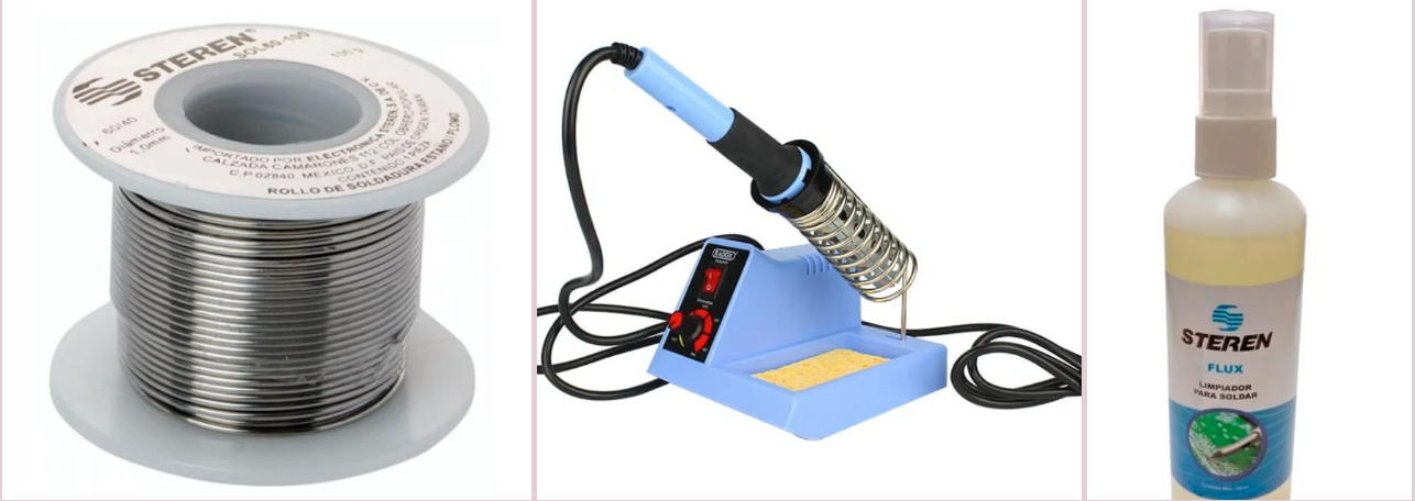
Soldering iron, solder, PCB, wire cutters.
2. Prepare & Heat
Heat iron to ~350°C, tin the tip with solder.
3. Solder the Joint
Touch iron to component & pad, apply solder.
4. Trim & Inspect
Cut excess leads, ensure smooth joints.
Testing the PCB
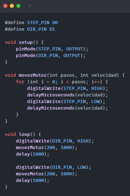
To test if the PCB is working correclty after soldering all the components I uplaod a code to the Xiao 2040 to move a step motor
This is the code I used, I programmed in the Arduino IDLE.
Then I just powered the driver with an external power supply
