5.- 3D Scanning and printing
In this week we will learn how to use the 3D printer, giving movement to a designed part, trying to show the advantages of 3D
printing over conventional machining. On the other hand, we will see the importance of "3D Scanning", and how useful and easy
the tool is.
We will take advantage of this assignment to start working on our project, starting by creating eyes and printing them on the 3D
printer and scanning a head that will serve in the future as a mold for the skin of our animatronic.
3D printing
3D BLOCK DESIGN
3D printing is a technology that allows you to create three-dimensional objects by adding layers of material. For the printer to make
our designs, they must be in G - code .
It is necessary to use a design tool to create our 3D object, so we decided to use "SolidWorks".
To begin, it is necessary to create half of the periphery of our eye, and through "Bossage/Base avec revolution", we create the entire sphere that will be the eye as well as a smaller circumference that will be the iris, note that it is not a complete circumference and that it has a straight cut in the iris area.
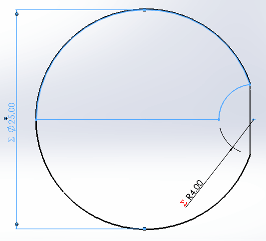
From the created circumference, we need to make a cut.
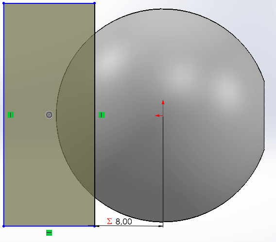
Once the cut is made, a "shell" is made so that the circumference is hollow, for that we choose the flat side and a thickness of 1 mm.
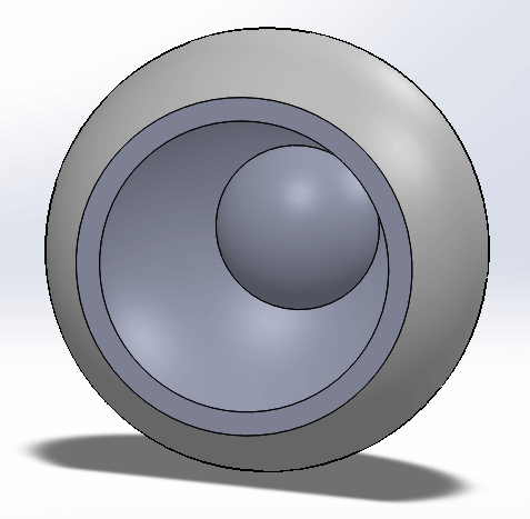
We make the base structure where the elements that will give movement to the eye will go, for that we first make a "sketch" and then "extrude" it with the desired length.
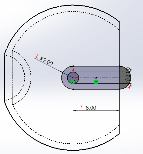
After this, we made another "sketch" to cut the middle part using the "Extruded Cut" tool, since the posts that join everything together will pass through there.
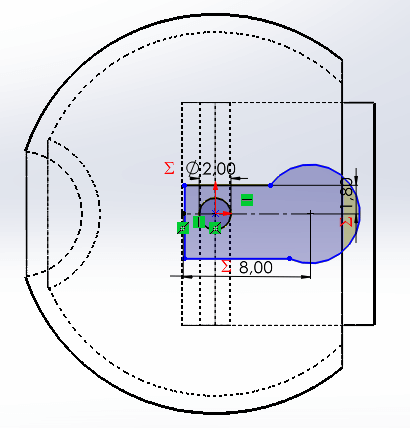
We add the posts, and the result is shown below.
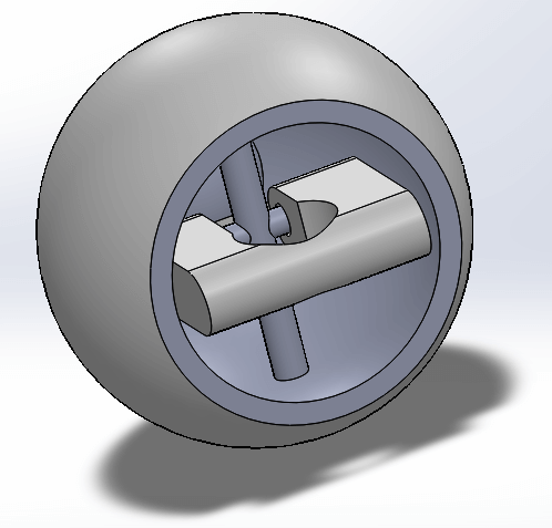
Lastly, we added a connection outside the eye.
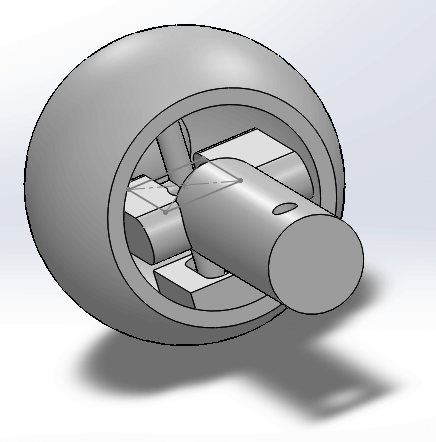
Once everything is finished, we proceed to save the file in ".STL" format, so that it can be transferred to the printer program.
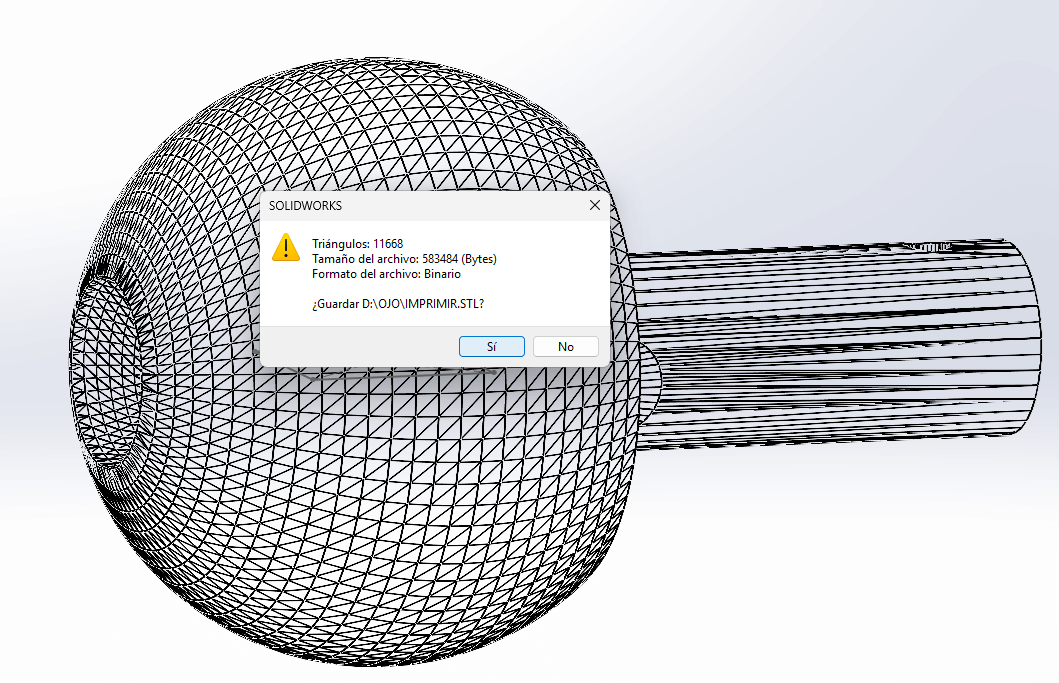
The ".STL" file can be found in the following link.
PRINTING PROCESS
The printer used was "PRUSA MK4S", so the "PrusaSlicer" program was needed, the software download link is presented below.
We open the "prusa" program and import the ".stl" file.
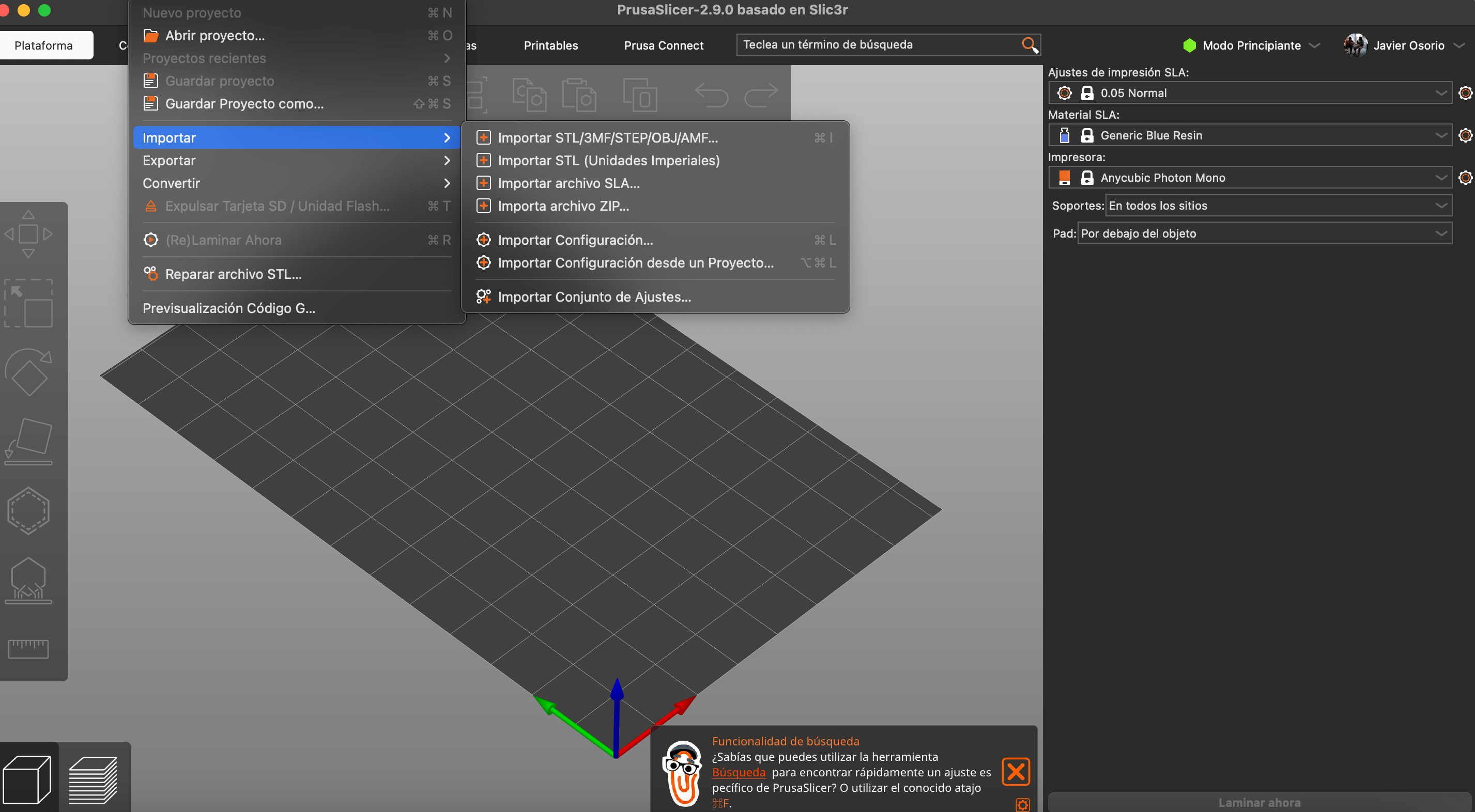
Another way to do it is to drag the ".stl" file to the work area, doing so will place the piece.
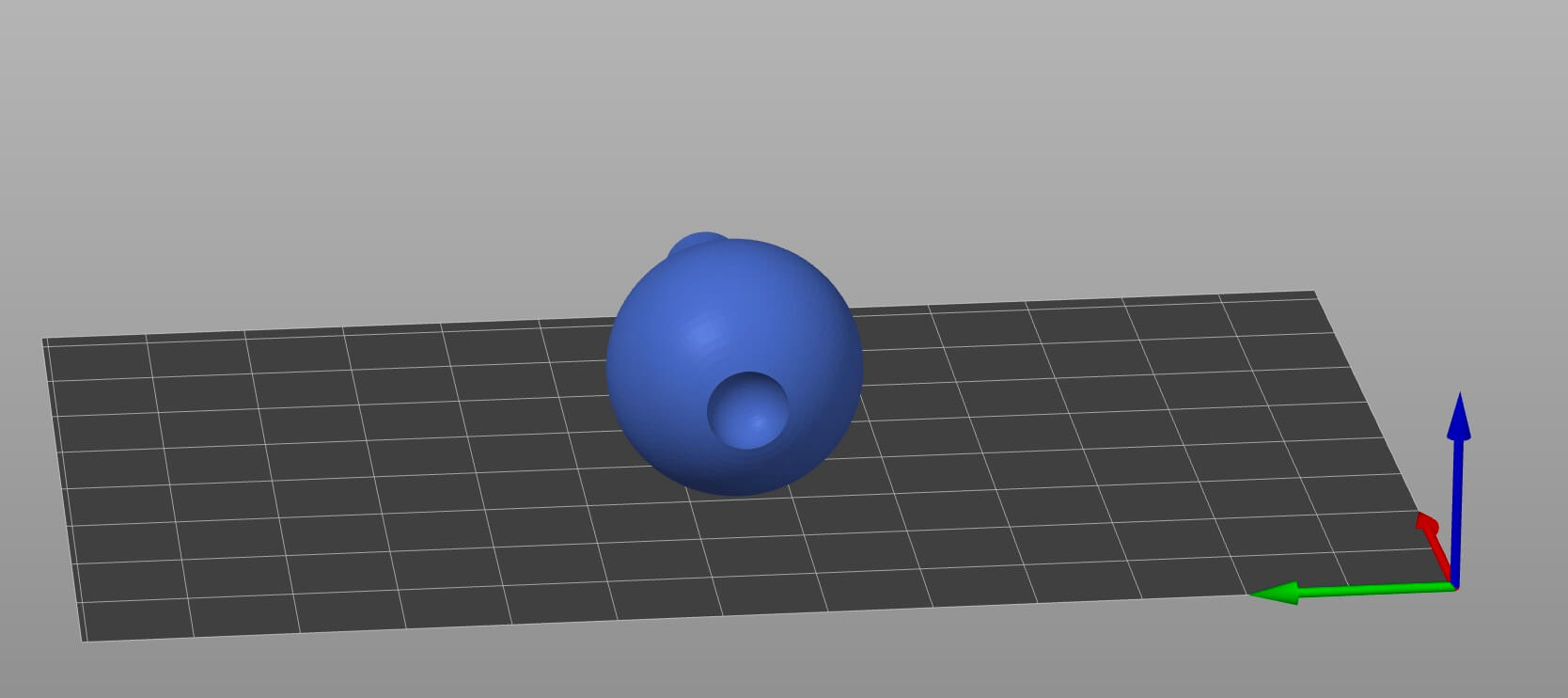
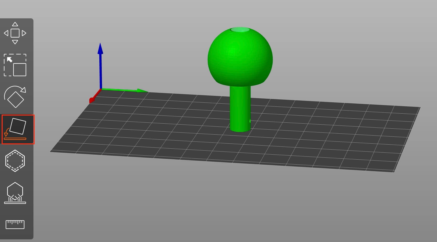
We can change the orientation of the object either manually or by selecting a face. To do this, you must first touch the object, this will open the side task bar, if we want the support point to be a face, we press the icon shown in the figure ("F") and clicking on the desired face, the program will automatically place it in the desired position.
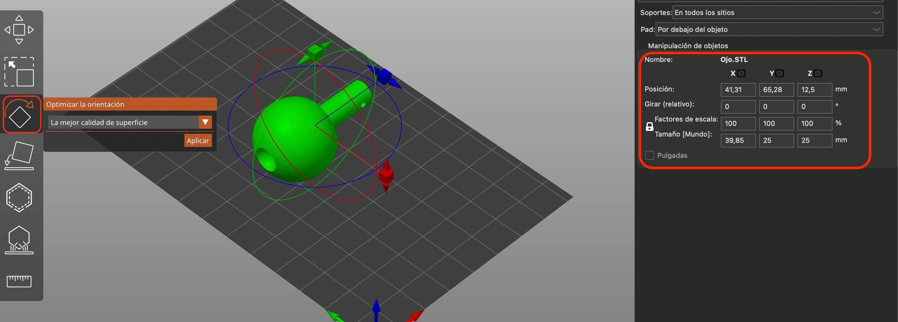
Another way to change the orientation of the object is by first selecting the piece and using "Rotate (R)" the three directions in
which we can rotate the piece appear as options.
The last way to do it is that when selecting the piece, on the right side the "x", "y" and "z" coordinates of the object appear, in
this section we can change the orientation giving a specific angle of the directions, as well as the position in coordinates on the plane.
To duplicate the piece, simply select it and use the "control + c" and "control + v" keys to create a duplicate.
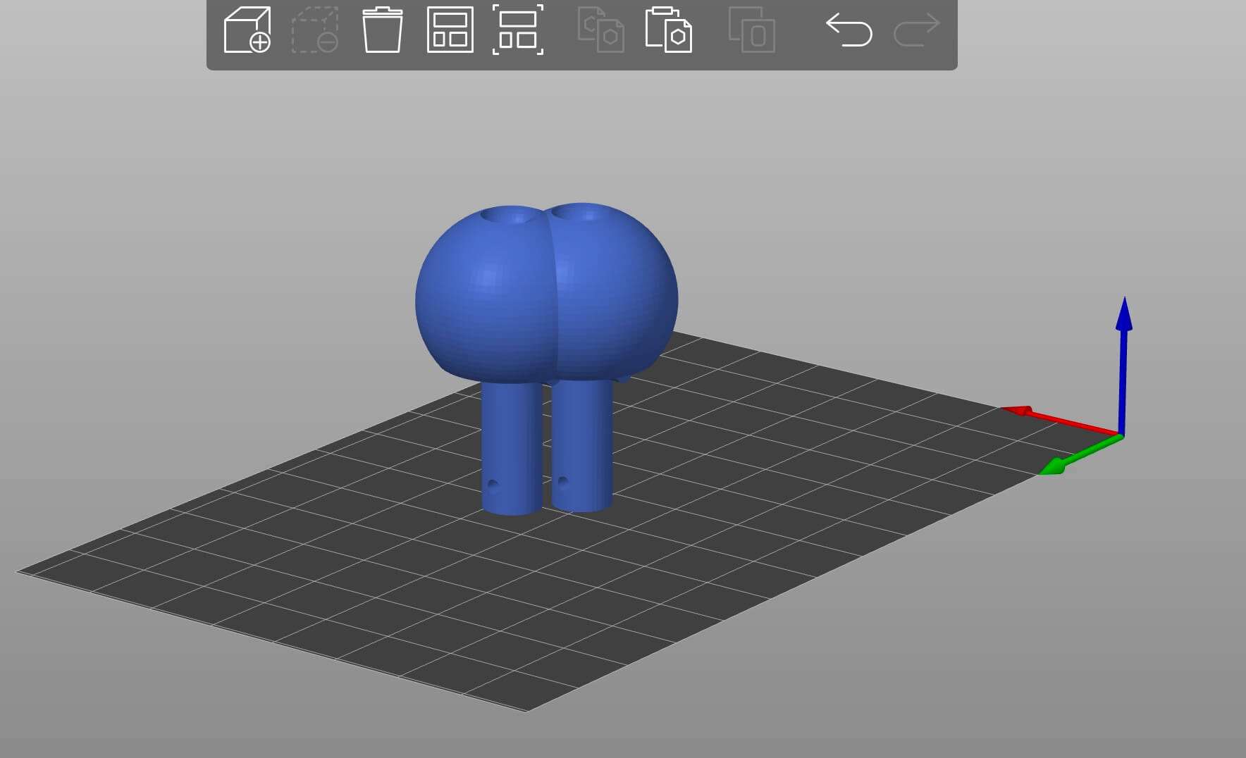
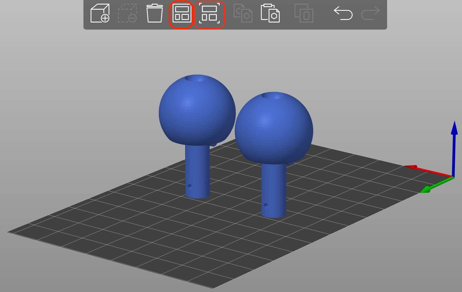
When doing the above, the duplicate piece appears as in the previous figure, to separate them we can do it manually, although it is recommended to press "Organize (A)" or "Organize the current base (D)".
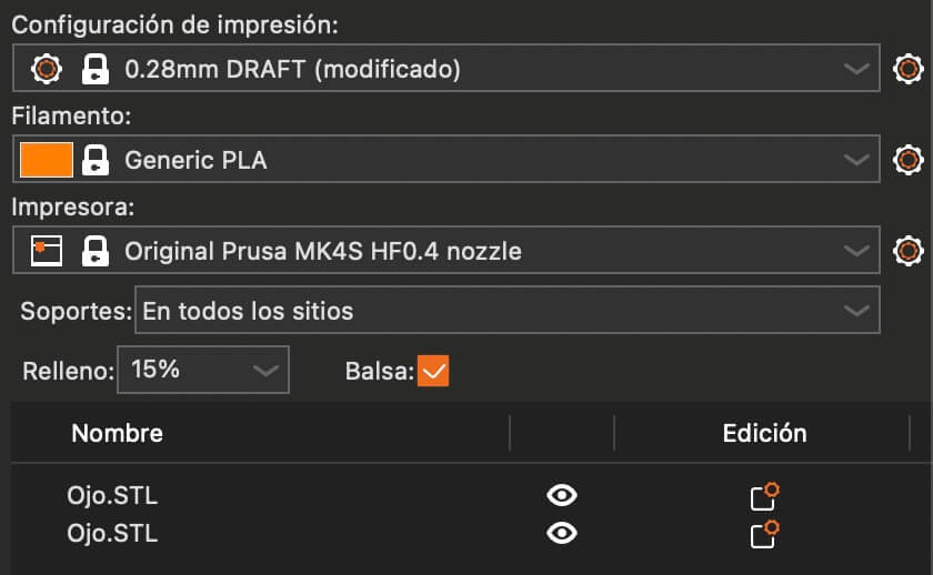
Once the pieces have been placed in the right place, we must configure the printing. The following image presents the relevant configurations.
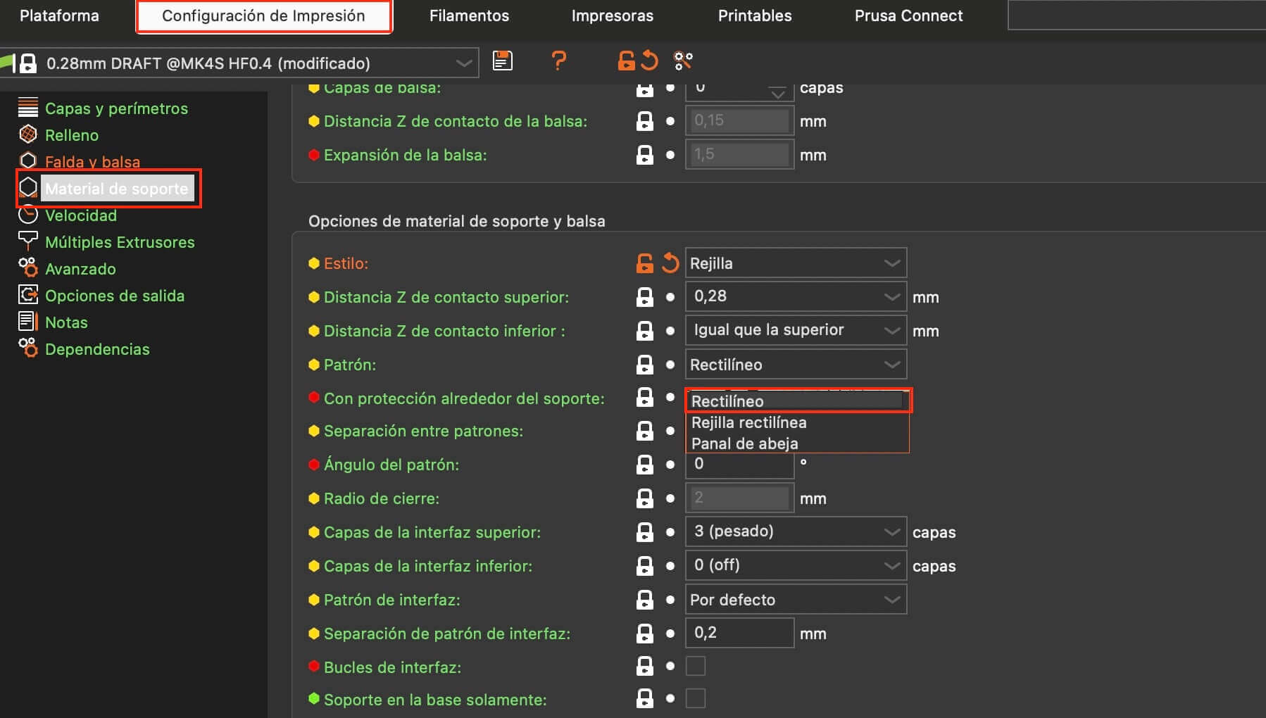
Finally, the supports for printing must be chosen, where the pattern selected was rectilinear.
To change the view and see what the supports would look like, you can click on the icon shown in the image.
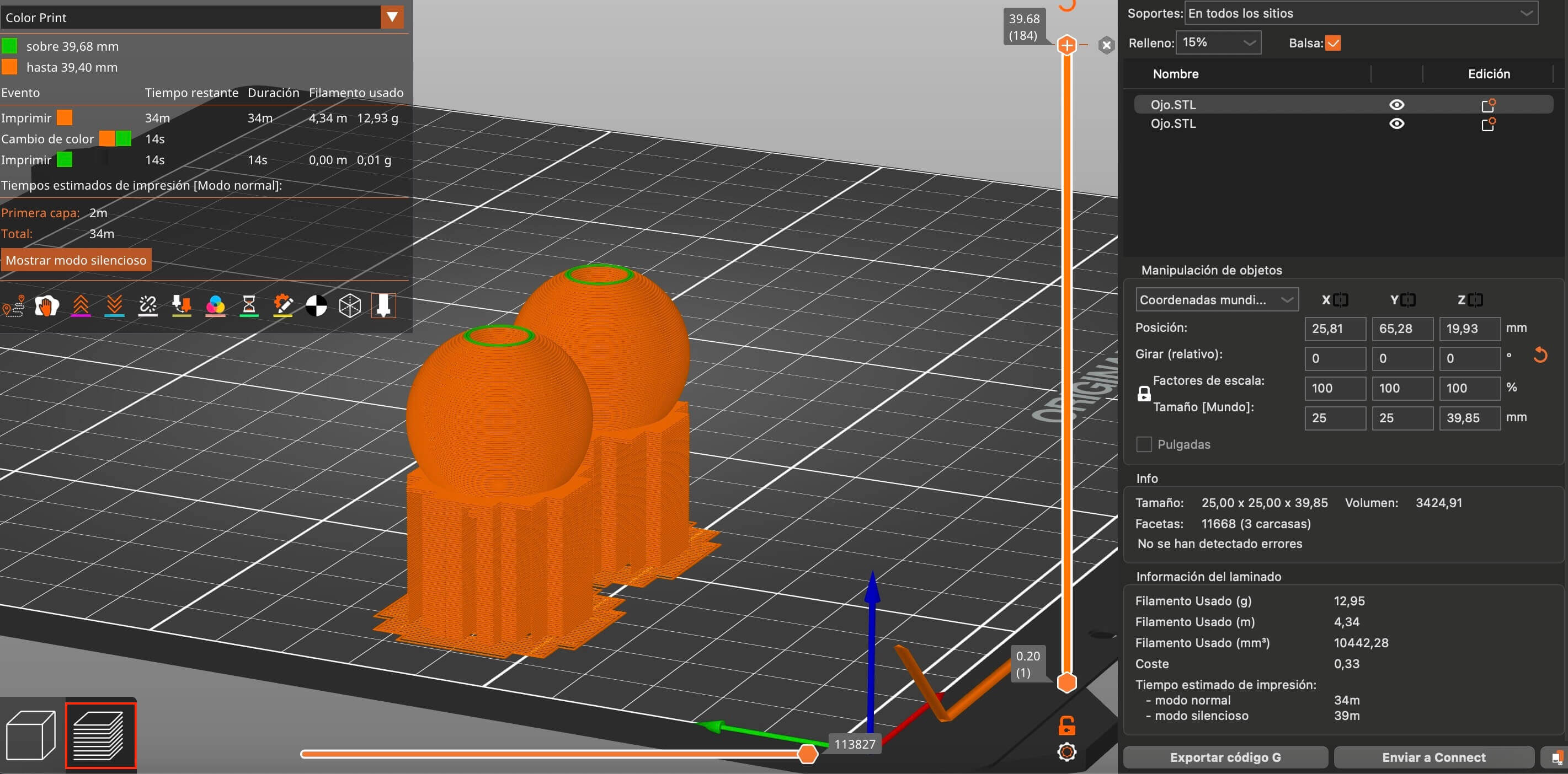
The bars on the side help us see what the supports would be like inside and the "G codes" generated will describe the movement of the printer. The following video shows what was described above.
Once all the above is finished, we export the G code, this option is located at the bottom left. By doing so, it opens a new window, where it asks us for a name with which the file will be saved and will provide it with an extension compatible with the "G code".
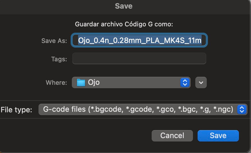
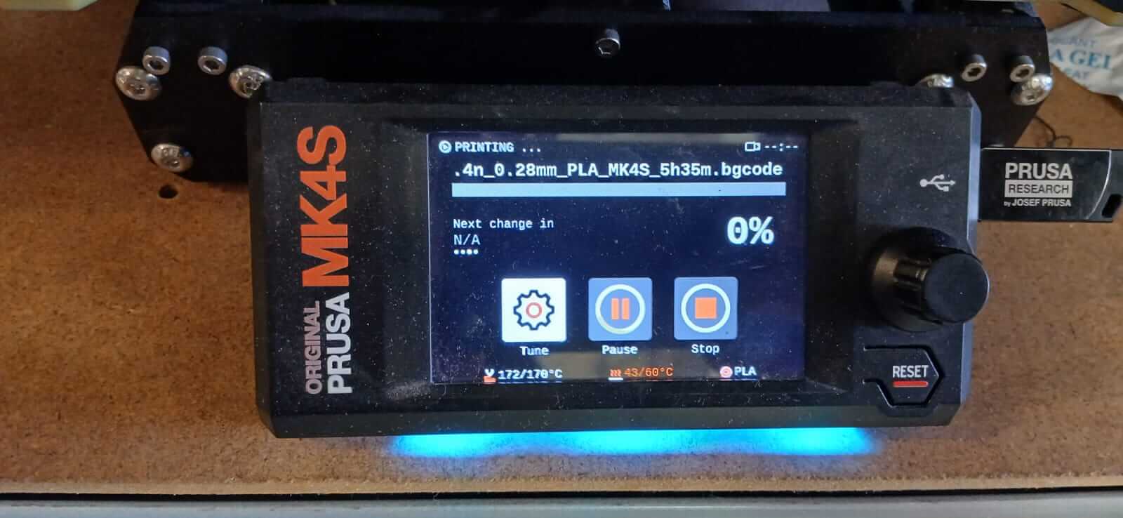
The previous file is saved in a memory and inserted into the "Prusa" printer, which will automatically detect our file, so it is only necessary to press "play" to start printing.
The figures below show the comparison between the rendered eye and the 3D printed eye.
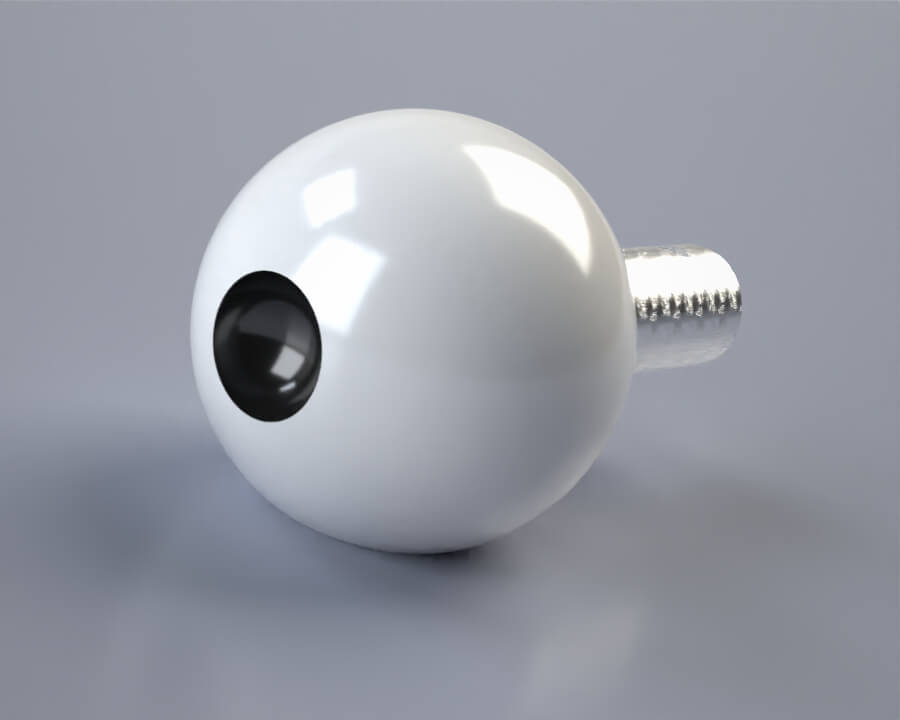
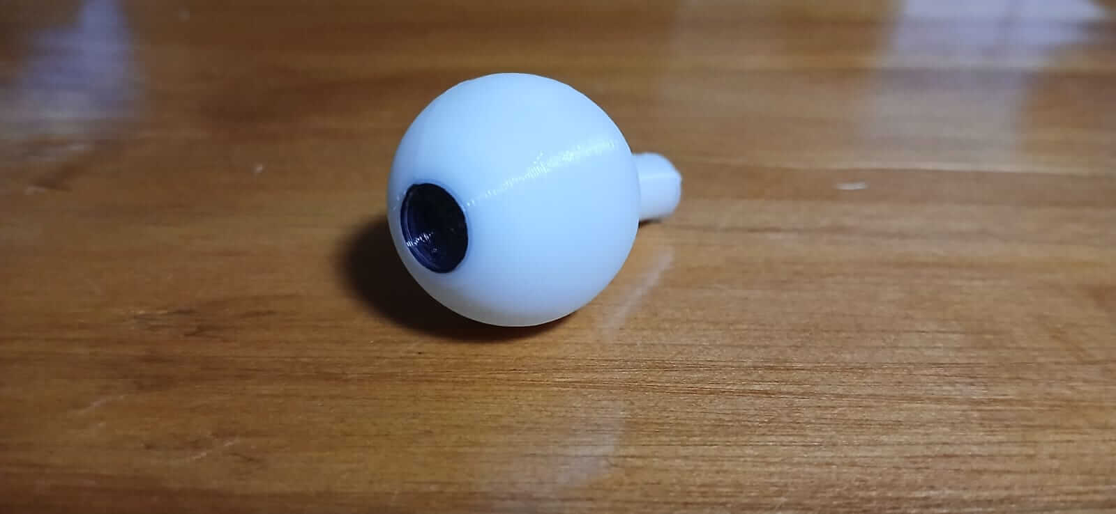
The moving eye is presented in the following video.
As could be seen, one of the advantages of 3D printing is that complex designs can be made that would be very difficult or impossible to make by other means of manufacturing. In the case of the eye, an internal mechanism equipped with movement was created without the need to make assemblies; This example shows the reach that the 3D printer can have, which makes it a very powerful tool.
Scanning an object
To perform the scan, the "Creality Scan" program will be used. When opening the program, we must choose the "scanner model".
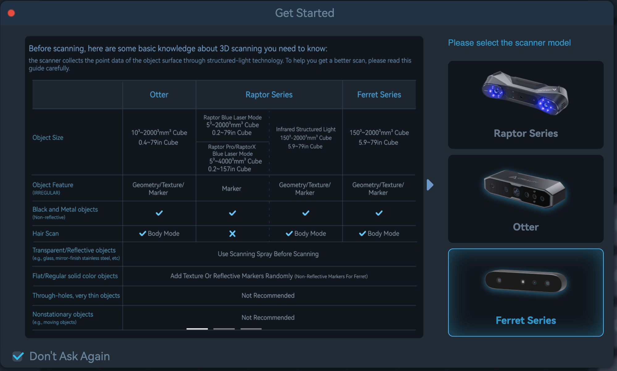
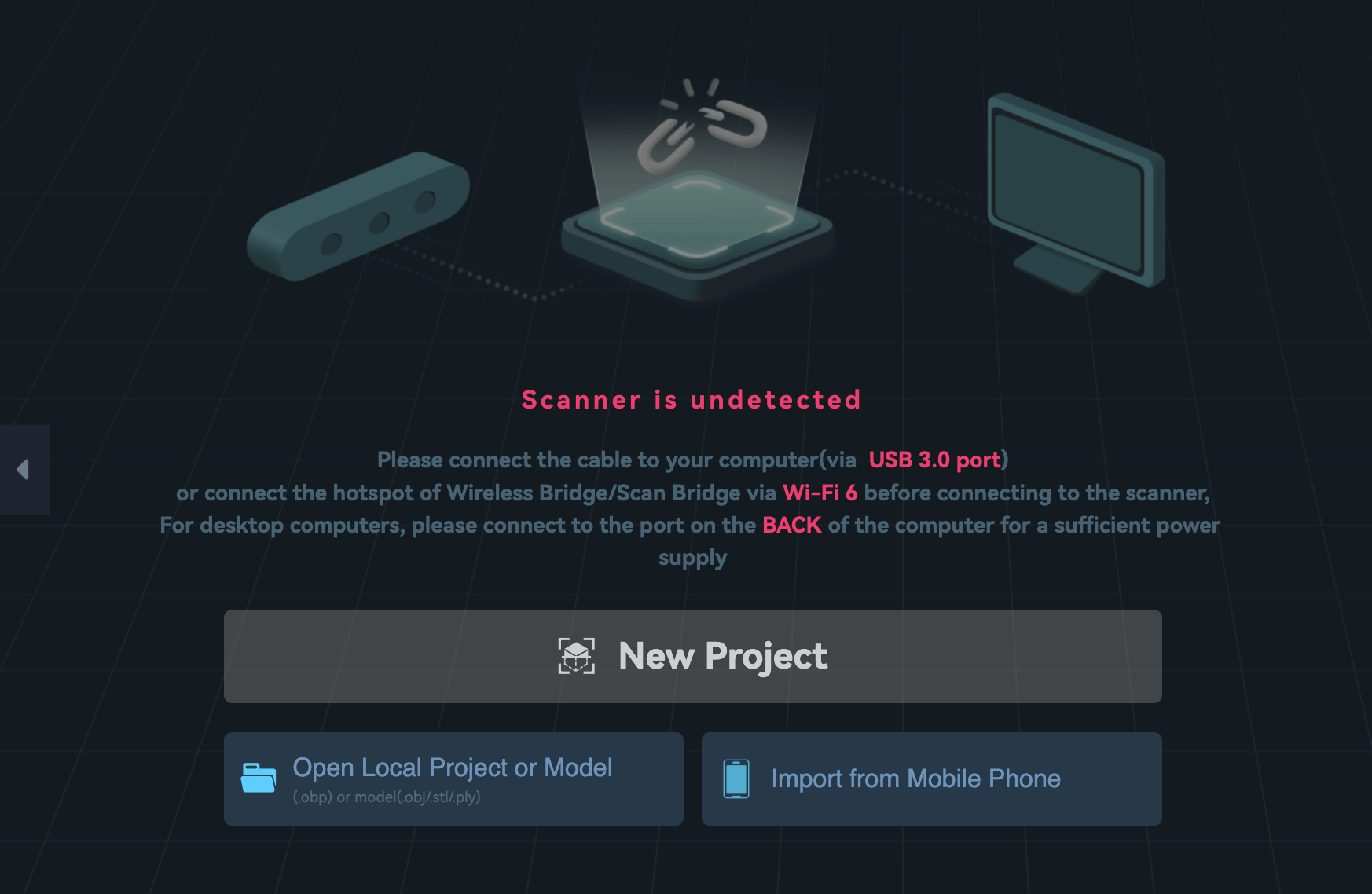
When choosing the model, a new window will open, in which we must select "New Project", it is important to have the scanner connected to the computer to be able to continue.
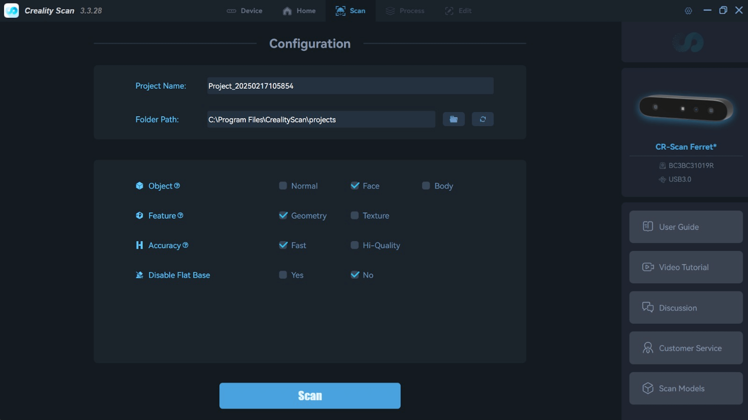
In the new window you must enter the name of the project, as well as the location it will have; In addition, certain characteristics of the element to be scanned must be selected, such as:
- Object
- Feature
- Accuracy
- Disable Flat Base
When we have these elements, we must press "Scan".
Once we are in the main window we must press "start". Let's notice that there is a side bar on the left side, which tells us how close or far the scanner is from the object. We must try to stay in the green or blue zone. If we leave these zones, we must move the scanner further or closer. If the object to be scanned is complex, we can place marks to help us scan in a better way.
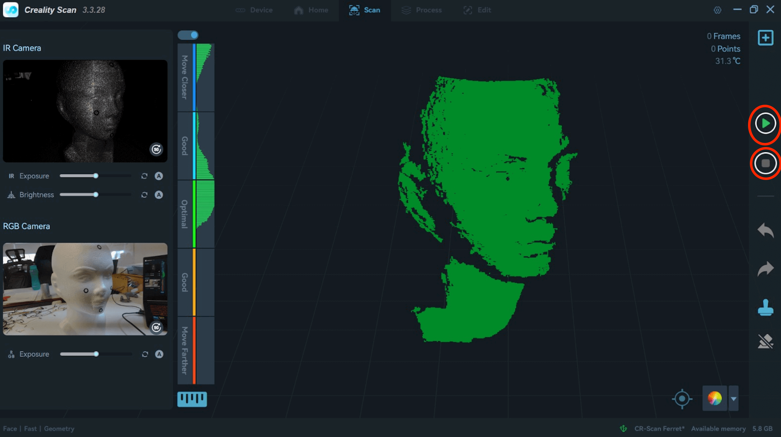
The video below shows the scanning process.
When it has finished scanning, we press the "stop" button, which opens a small window, which asks if we want "complete scanning", if so we press "yes".
We wait a moment and the menu on the left side changes, it is recommended to press "Optimization Settings" in the tab, to change the "resolution" or "sensitivity".
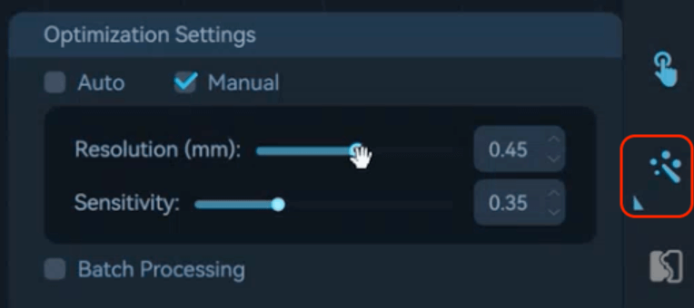
Once all the changes have been made, we press the button to start processing. After the process, we can select "Mesh", which converts all the points (which are thousands) into triangles between each point to generate a surface.
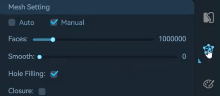
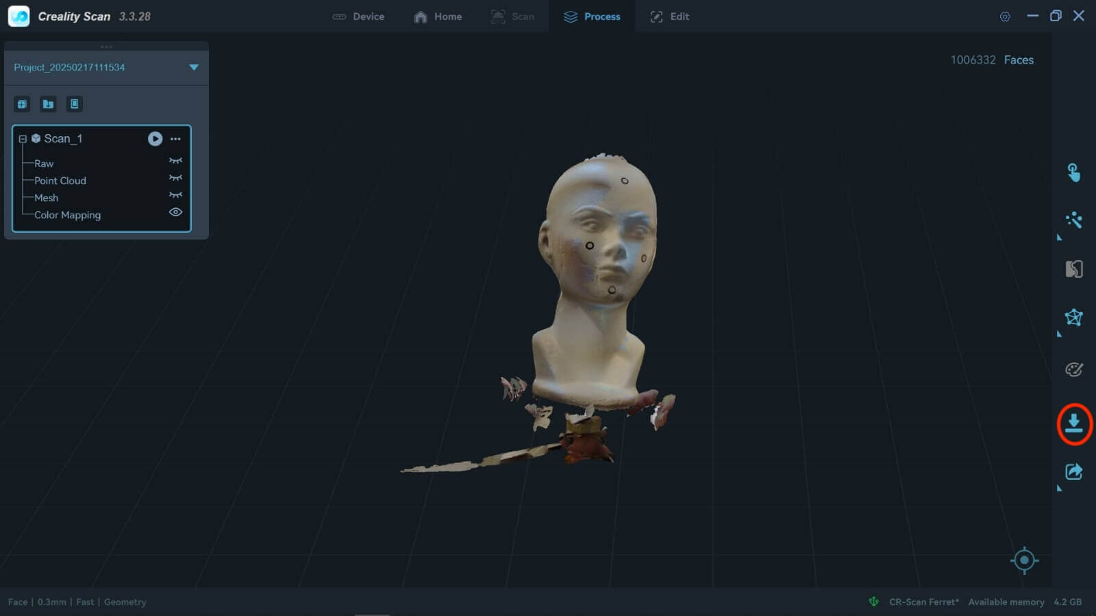
We press "Color Mapping".
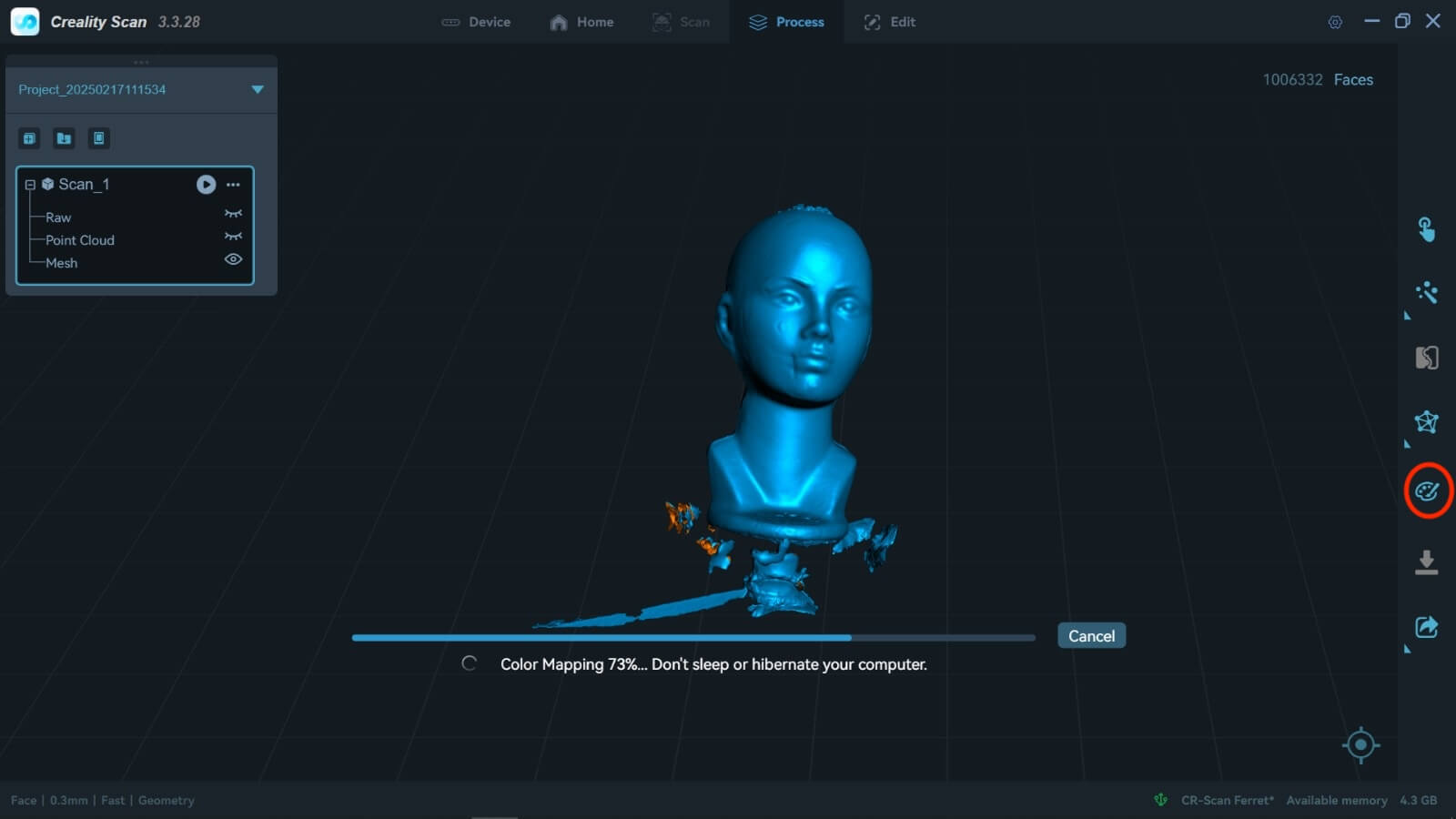
At the end of the process, it shows us the scanned image with its real color. If the result is the desired one, we proceed to export the file in ".stl" format.
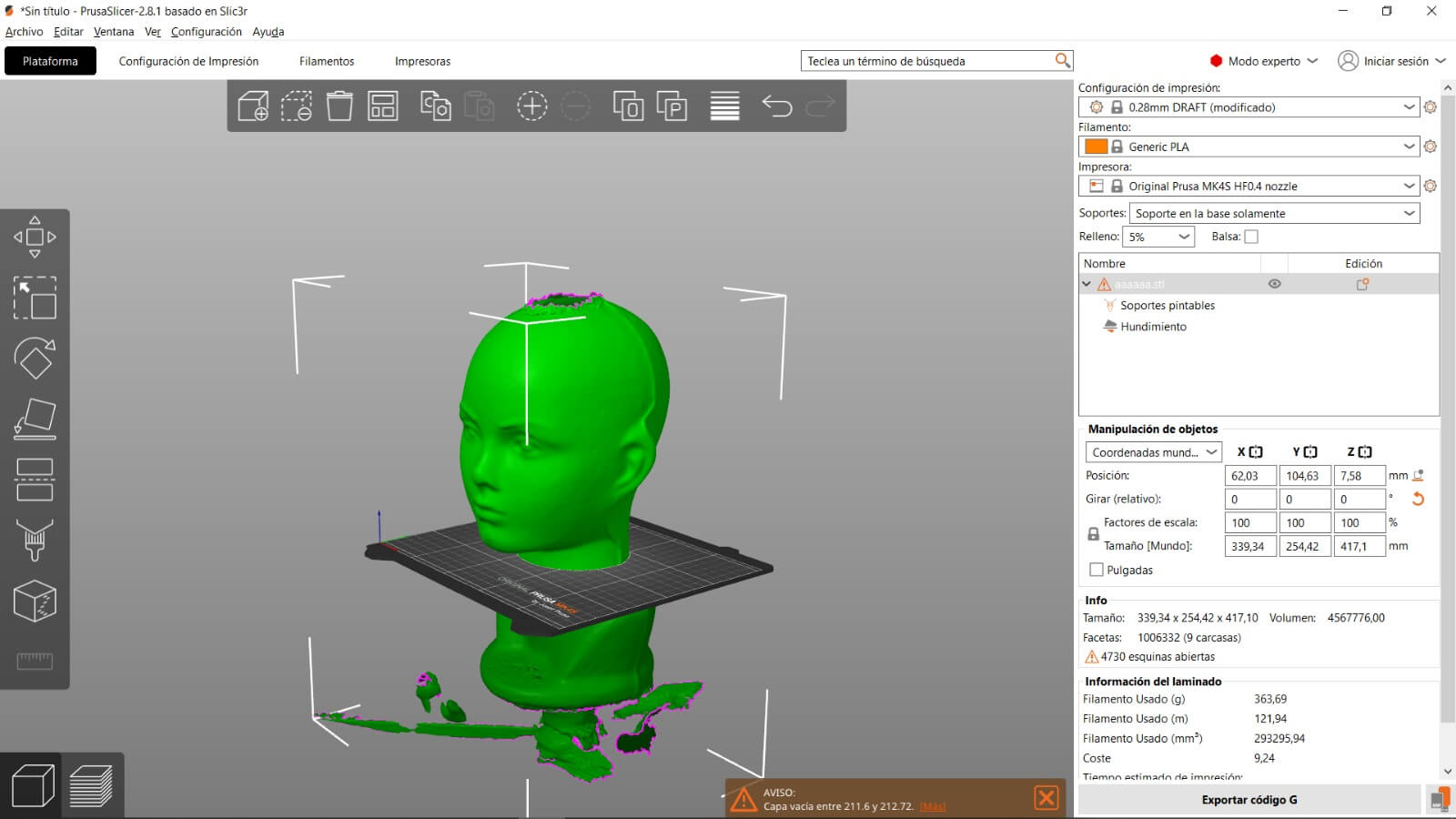
We open the "prusa" program and import the ".stl" file.

Once there, we arrange the piece and save the information on a "USB" to connect it to the "Prusa" printer.
The printing process is shown in the following video.
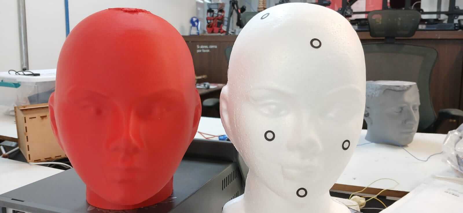
The printed figure is shown below.
File
Learning outcome
This week we learned the use of the printer and 3D scanning, paying main attention to tolerances when designing pieces, as well as the characteristics of the printing and the type of filament to use. The type of filament is important, since its advantages and disadvantages must be considered when choosing it. We use PLA because of its low cost.
