3.- Computer controlled cutting
This week we will learn the use of parametric design tools (SolidWorks), as well as the proper use of the laser and vinyl cutter.
Parametric 2D modelling processes
The next section presents the use of the "SolidWorks" tool, where the formulas will be used to place the parametric elements in our designs, with the objective of modifying the drawings by simply changing the values of the parameters.
Parameters and drawing
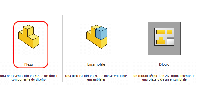
To begin, it is necessary to open "SolidWorks", where we select "Part".
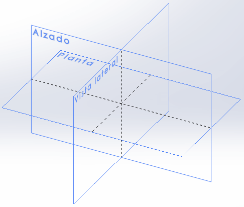
Once the above is done, our work view opens where we must choose a plane, in our case "Front Plane".
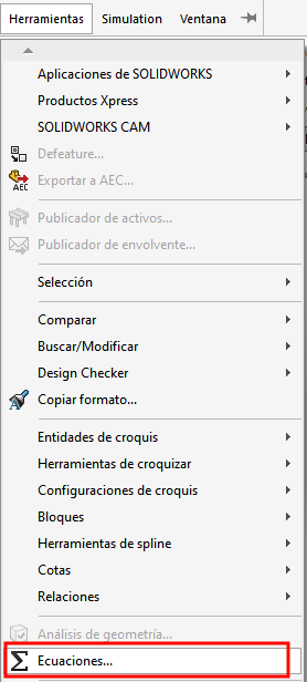
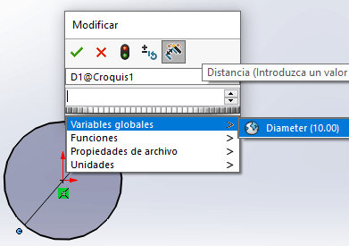
- Parameters from "function". The first thing to do is go to the "Tools - Equations" menu. A new window will appear there, in whose global variables section, we write the name of the variable, as well as its value and, if desired, a brief description. You can place as many variables as necessary, as well as references between different variables.
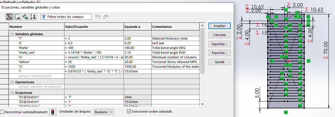
Once the parameters have been declared, they can be used to size any figure that
can be modified automatically by changing a value. To place a parametric dimension,
it is necessary to dimension and place "=", which will display a menu of global variables
where we can select the variable we want. Another way to do it is to put the name of the
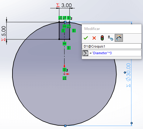
variable in quotes after the "=". It should be noted that we can do operations with
global variables.
If the steps are correct when click Enter, the " Σ " symbol
appears next to the dimension.
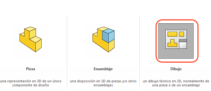
When all the pieces have been designed, it is time to place them on a plane to follow the laser cutting process. So, you need to open a "drawing".
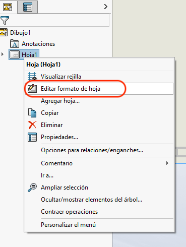
When opening the drawing window, it will ask us to choose the paper size, later, at the root where we have "Sheet", we look for "Edit sheet format", with this we eliminate all the margins of the sheet that appear by default, if not, the laser cut will also cut the margins.
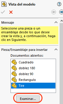
To place the pieces we need, it is necessary to enter the "Drawing" bar and press the "model view" icon, which will open a new window where we must "search" for the pieces we want to include in our cuts.
Once all the elements and designs have been placed, the document must be saved in a "DXF" format.
Files
Laser cutter
Since the designs have been made in SolidWorks and with the files saved in .DXF format, the "SmartCarve4.3" program must be opened. The download link for the program appears below, as well as the manual.
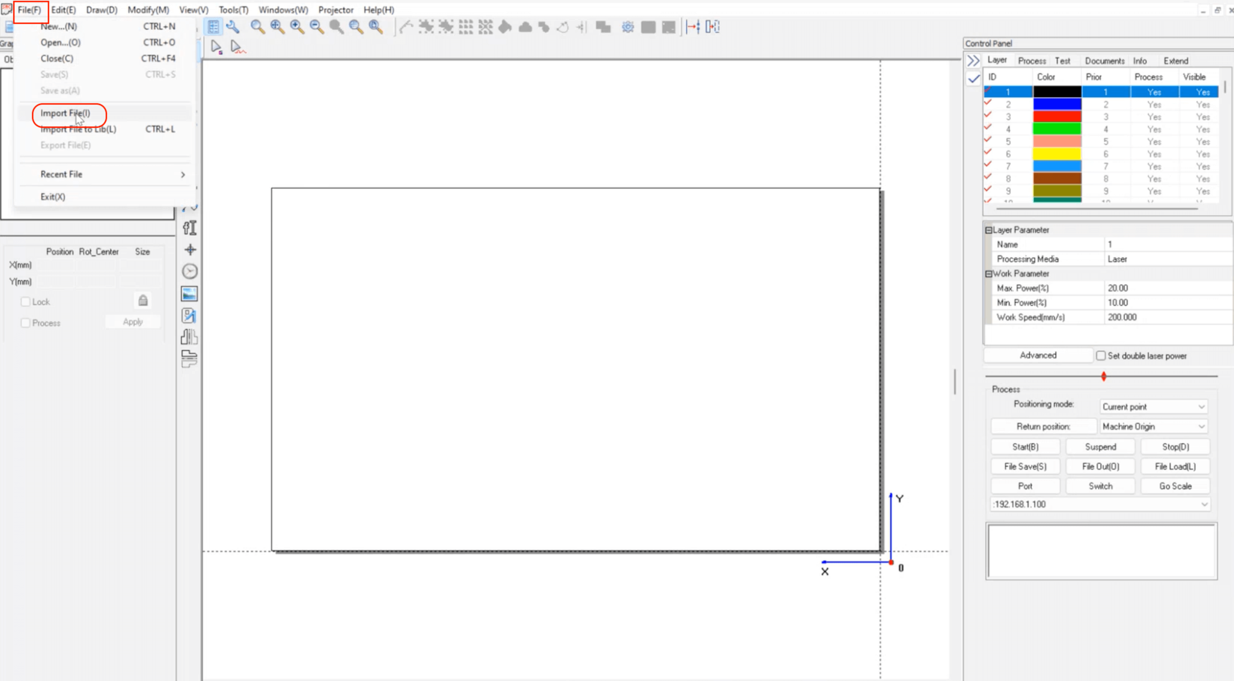
When we are in "SmartCarve", we must go to "File (F) -Import (I)". We look for our .DXF file and click "open" and we place our design in the lower right corner.
At this point we can do two things; make the entire layout in SolidWorks and only import the .DXF or place each individual piece (in .DXF format) that we want to cut and from here make the entire layout.
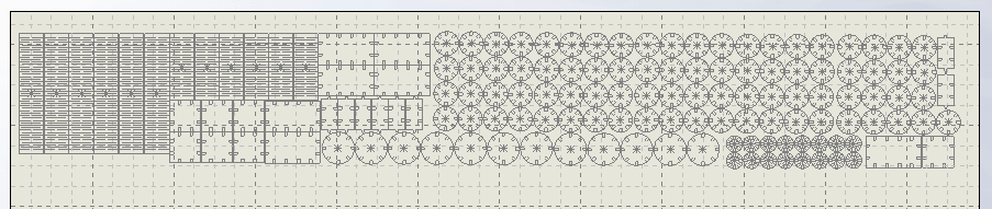
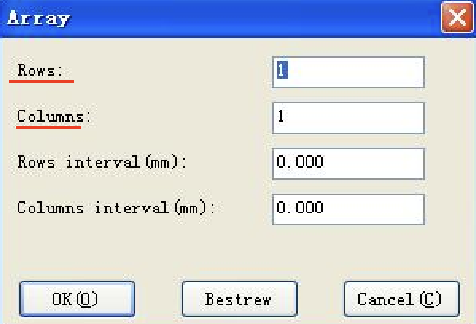
If we place each piece individually, we can create an arrangement. To do this, we select the piece we want, right click the mouse and in the menu, we look for "Clone(E)", which opens a new window, where we place the number of rows and columns that we want for the arrangement.
This way of placing the cutting pieces optimizes time and minimizes material waste.
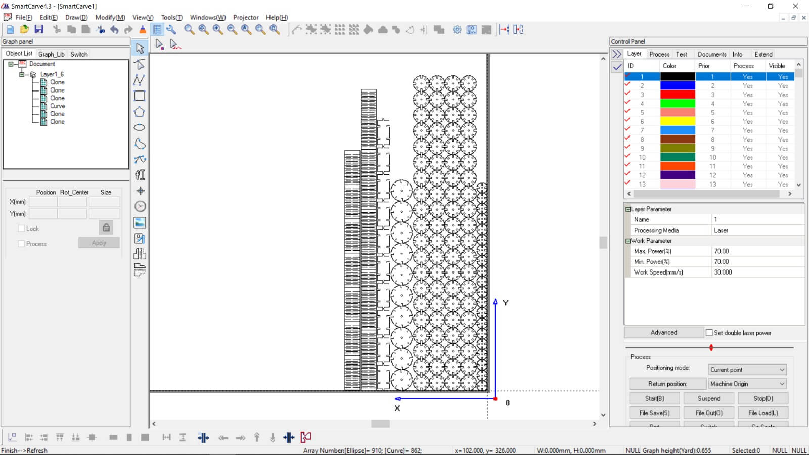
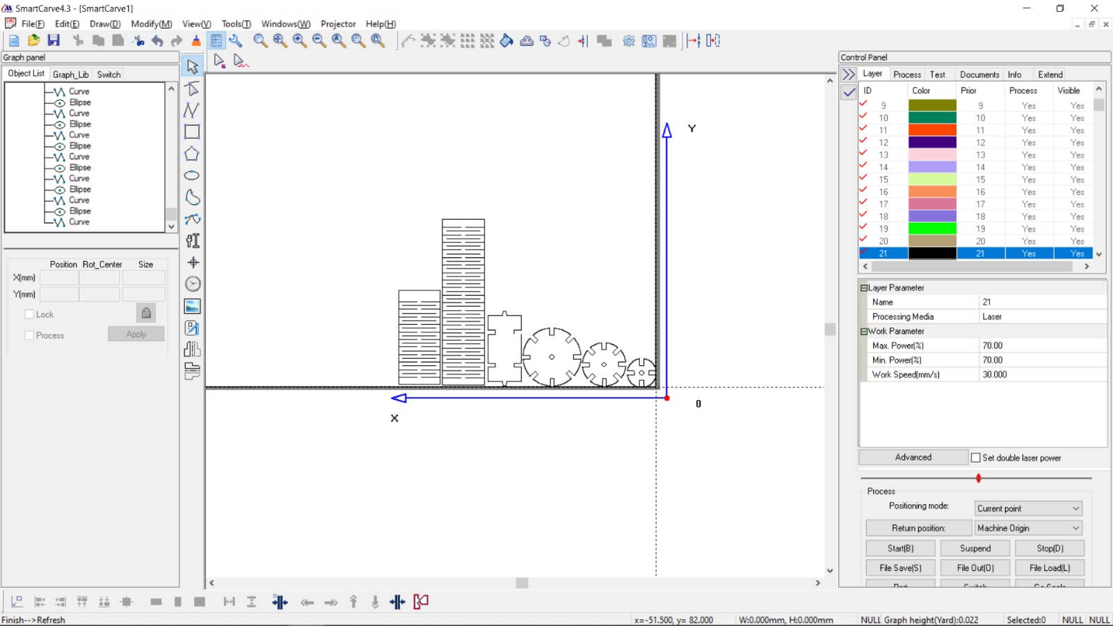
Now it is time to assign a layer to our pieces, for that we select our piece and assign a layer to it. Each layer can have different "Power and Speed" characteristics, the values assigned are based on tests at the time of cutting, some typical values are "Max power = 70" and "Work Speed = 30".
Once all the pieces have been placed and all the layers have been assigned,
it is necessary to check that the images or lines do not intersect, for that
we right click and select "find overlap lines" so that the tool shows if
there are errors or overlaps, if so, we must correct them, otherwise, we
are ready to start the laser cutting.
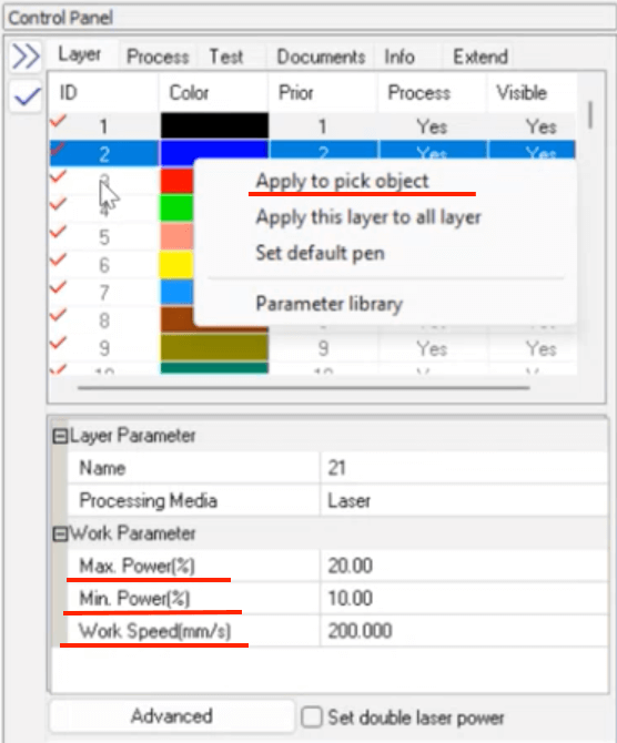
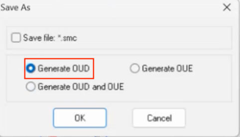
If the computer is connected to the laser cutter, press "Star(B)", if this is
not the case, press "File Save(S)" to generate an .OUD file that will be
saved on a USB memory, which can be connected to the laser cutter.
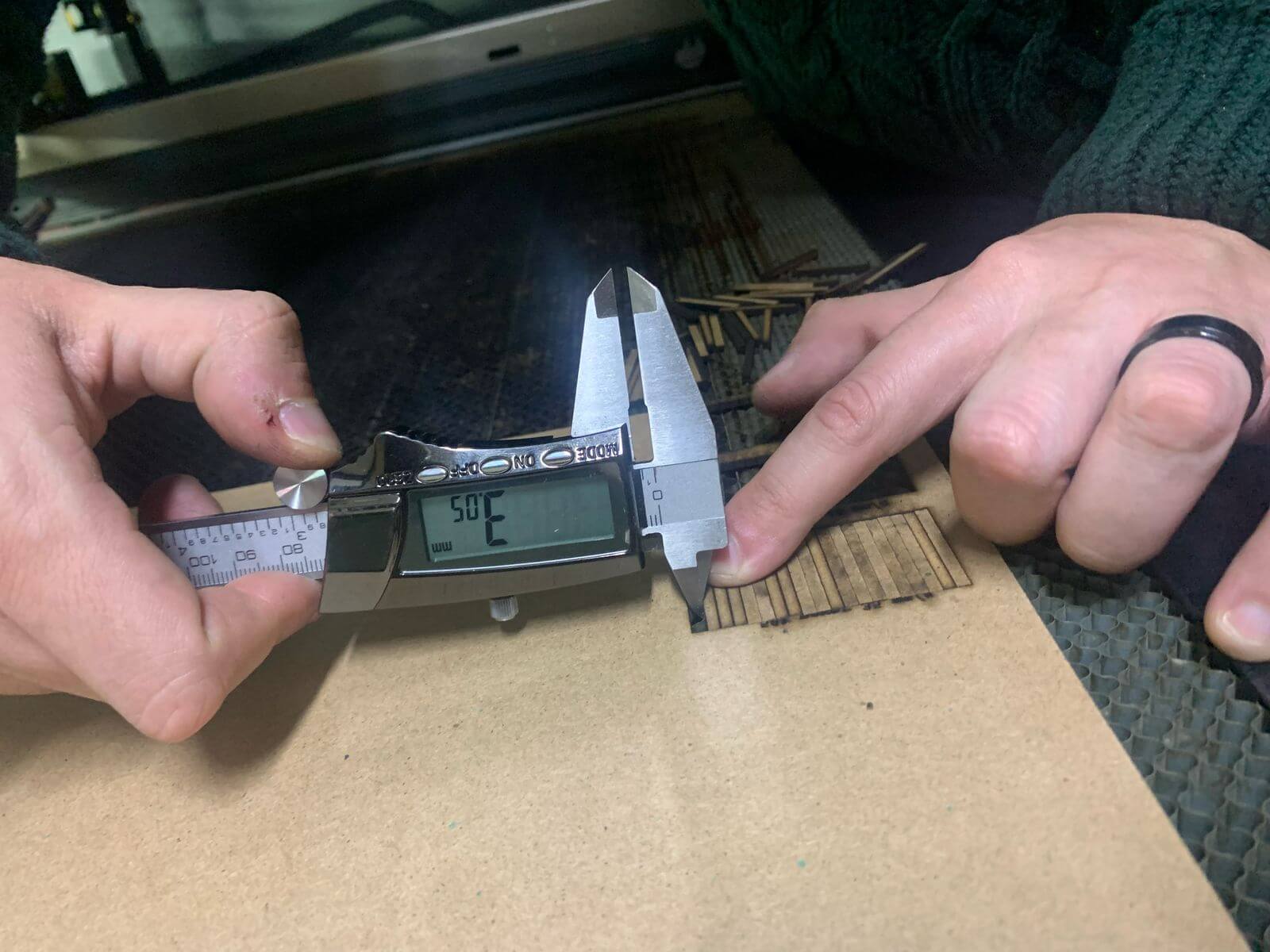
Before starting to cut, it is important to have certain considerations such as the "kerf".
Kerf in laser cutting is the width of the groove produced when cutting a
material with a laser. The width of the kerf affects the accuracy of the
piece, and the amount of material wasted. The "kerf" can be calculated
by dividing the gap by the number of cuts (3mm/20), in our case the "kerf"
was "0.15mm", which must be considered during the design of the parts in SolidWorks.
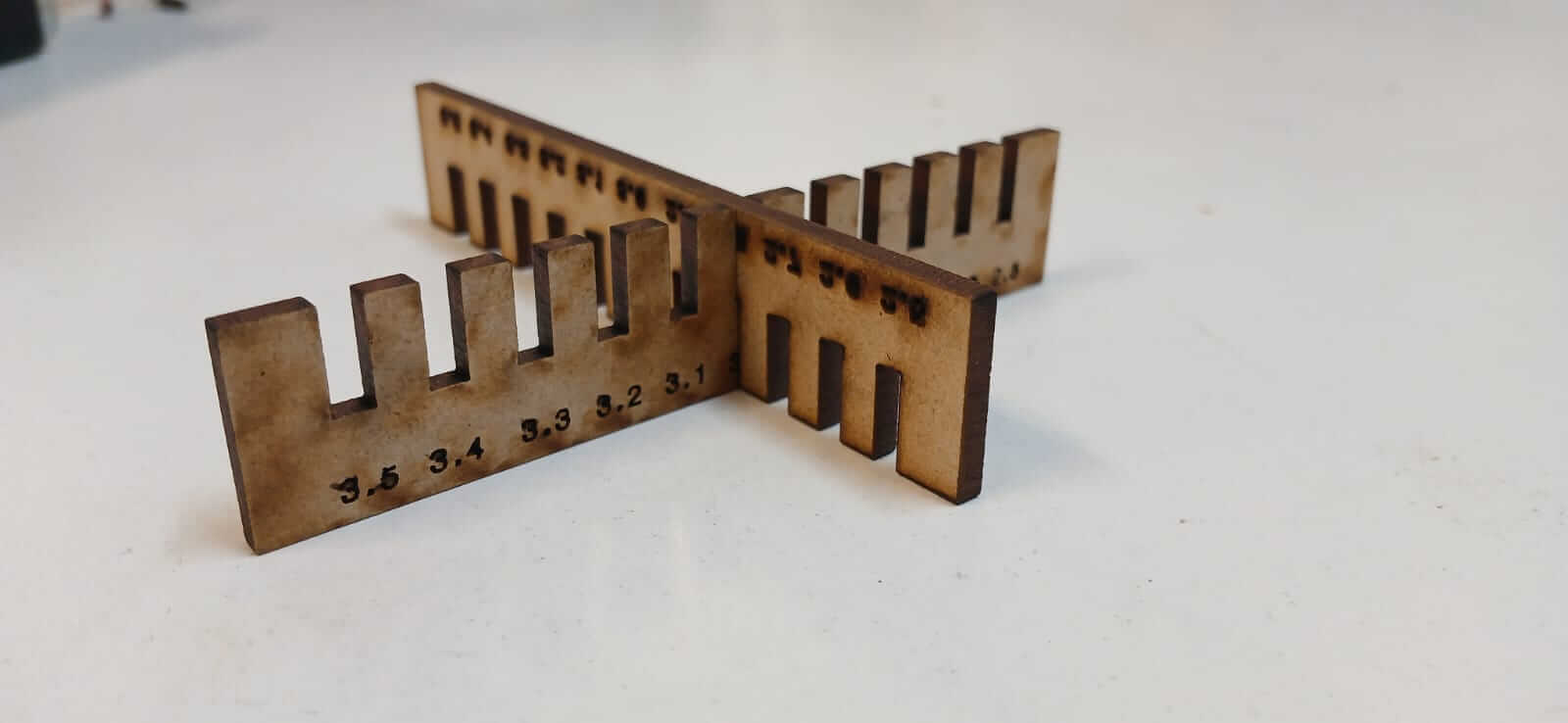
Another way to know how our pieces will fit together is through the "Combs to joint clearance test".
More information about the laser cutter, materials that can be cut, Kerf, joints and more, can be found in the link below.
MY FIRST STEPS WITH THE LASER CUTTER
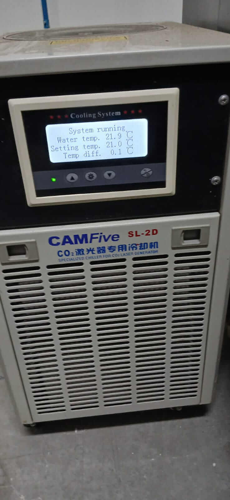
Before printing, the first thing to do is turn on the ventilation system and the laser cutter, to do this you have to follow a series of steps.
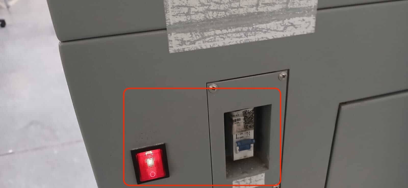
- Turn on the ventilation (the power button is located on the back of the laser cutter).
- Insert the Key at the top of the machine and turn on.
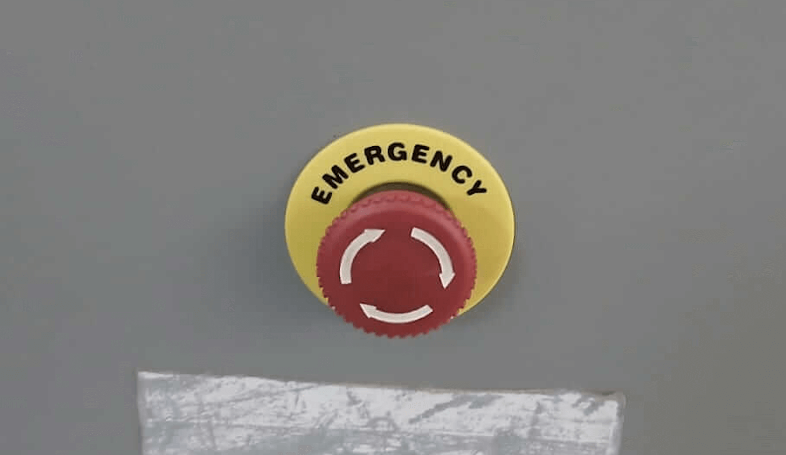
- Release the STOP button.
- Turn on the machine (right side of the laser cutter).
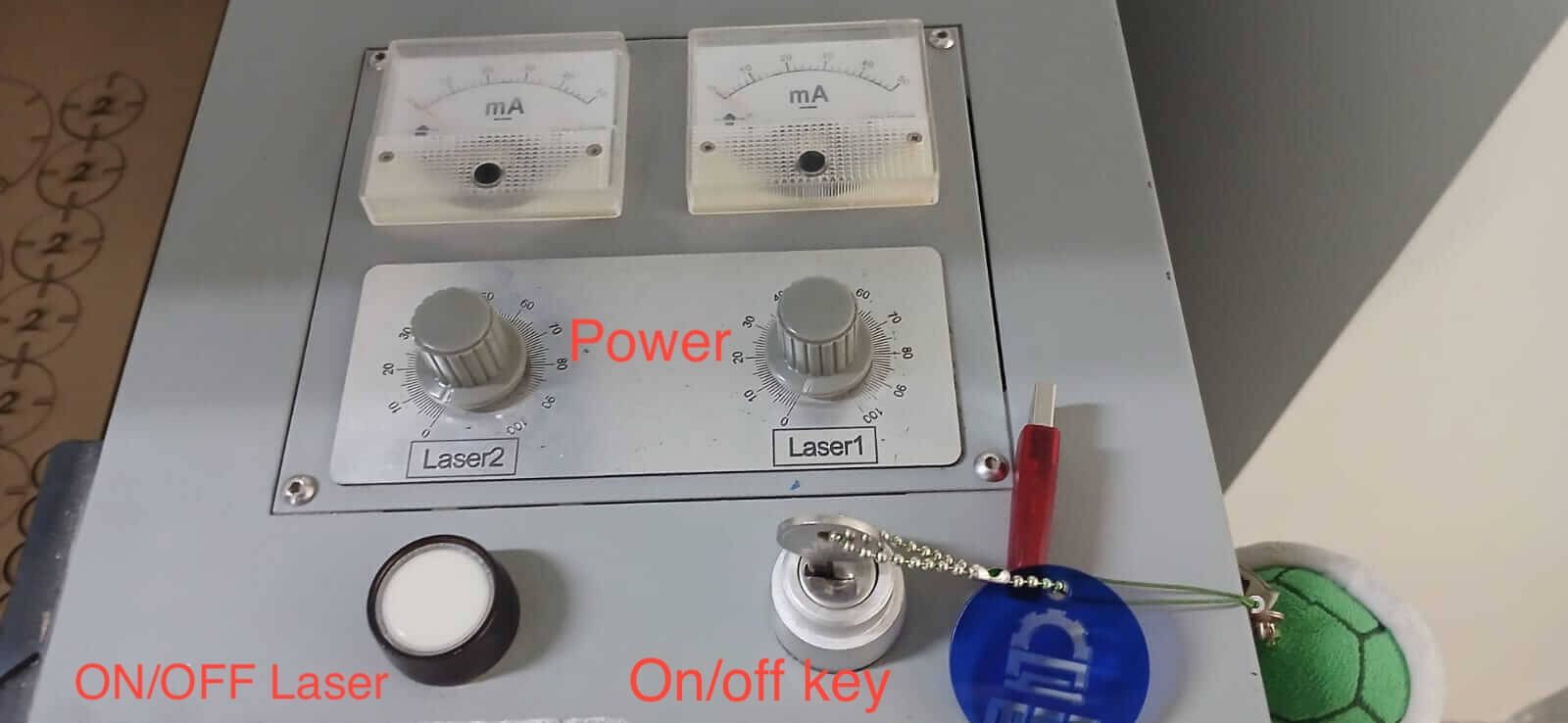
The cutter has two lasers, we can work with both or just one. If we work with both, the cutter will pass through the same place twice, so it is r ecommended to work only with one laser, due to this, the laser that is not used must have "0 power". Important note, the laser must be always turned off for safety reasons, it will only turn on until it is time to start cutting; Once the cut is finished, it must be turned off again..
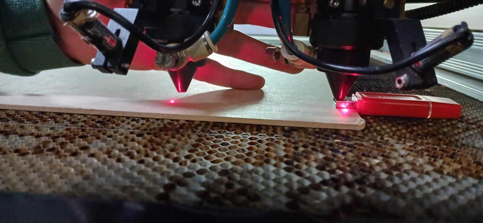
To continue, it is necessary to calibrate the distance between the laser and the material to be cut, the recommendation is 5mm (we can use a USB as a reference, as shown in the image). To calibrate it is necessary to loosen the screw that holds the laser stationary, lower it and tighten the screw again.
Once the laser has been calibrated, it is necessary to set an origin. To do this, with the help of the arrows we place the laser where we want it to start and press "enter". If everything was done correctly, we can move the laser with the arrows in any direction and by pressing "origin", the laser must return to the "origin" that we defined.
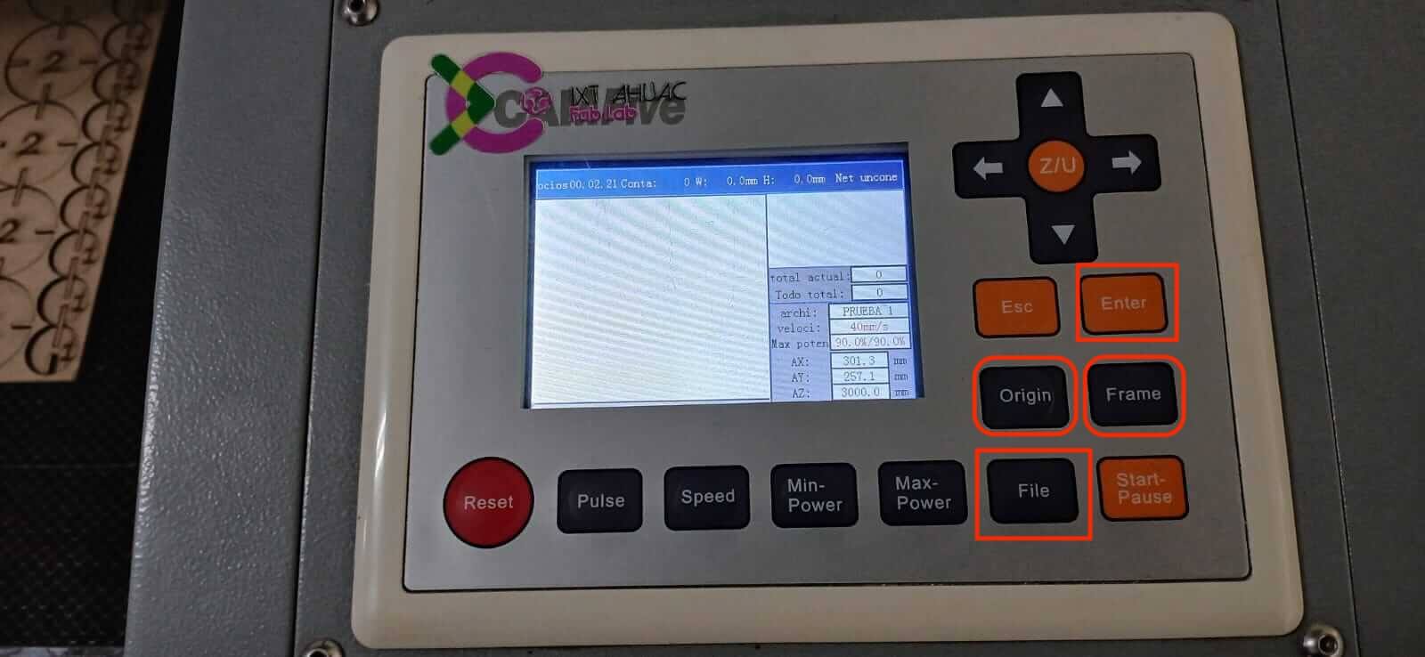
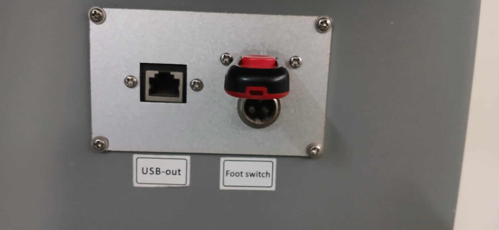
It is necessary to connect the USB to the cutter (the port is located at the bottom of the panel) and using the "File" button we can search for our file. When we have found it, we must copy it to the cutter. If the procedure has been correct, our drawing should appear on the screen.
An important step would be to press "Frame” and see the path that the laser takes in order to ensure that we are within the margins of the material.
If everything is correct, we must lower the lid of the laser cutter for protection, press the laser power button and press the "Start" button, at which point the laser will begin cutting.
When you finish making the cuts, before lifting the lid it is important to
"turn off the laser" .
To turn off the machine, the steps are reversed.
- Turn off the machine (right side of the laser cutter).
- Push the STOP button.
- Turn the key back (turn off).
- Turn off the ventilation (the power button is located on the back of the laser cutter).
Finally, the cuts are removed, and the work area is cleaned.
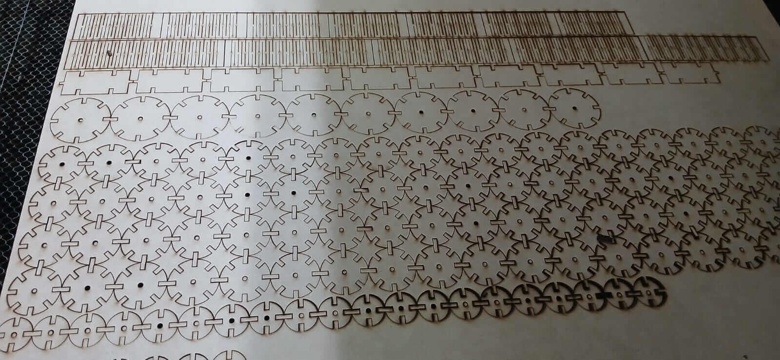
Parametric construction kit
Once we have all the pieces cut, we proceed to use our imagination and make some creations.
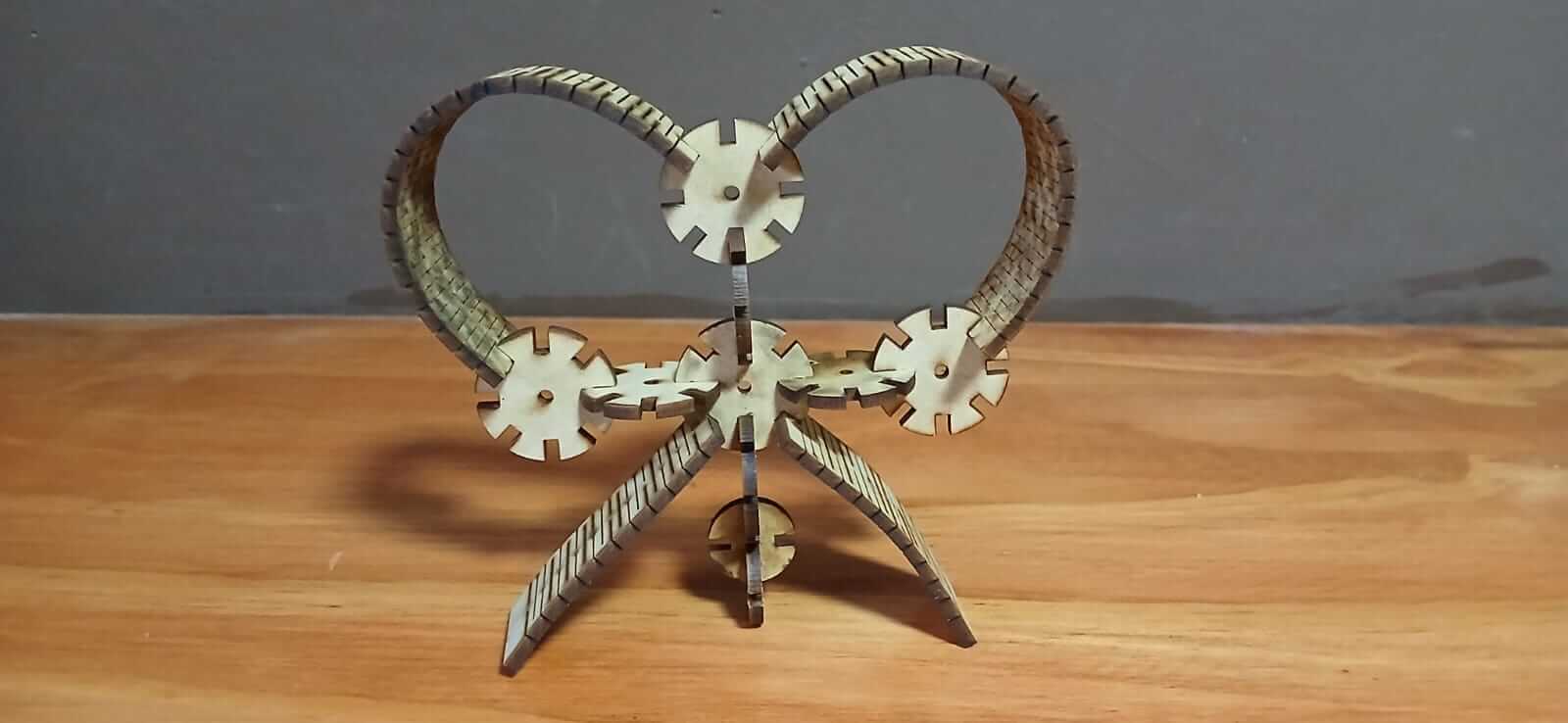
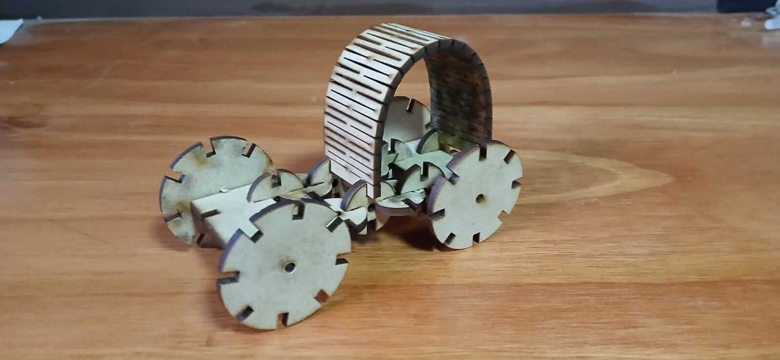
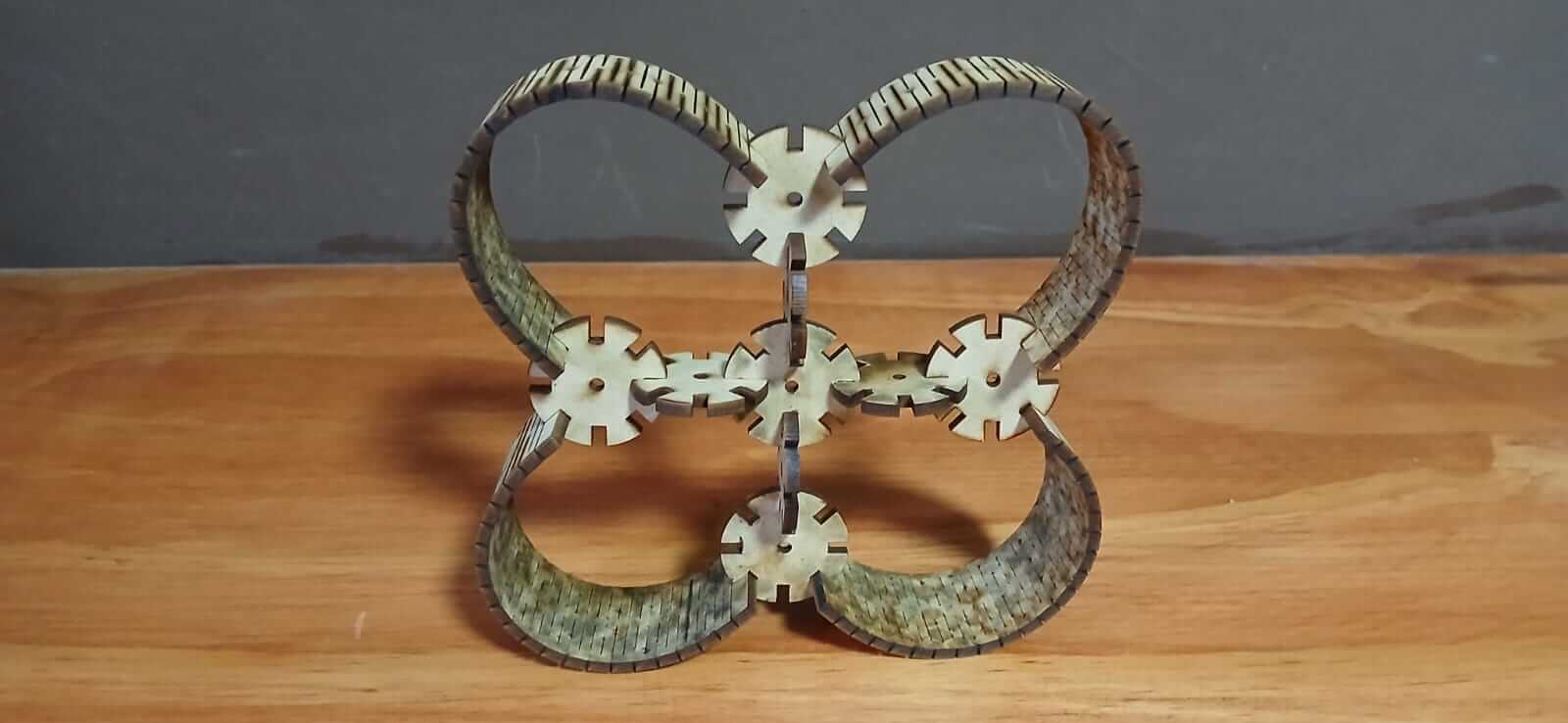
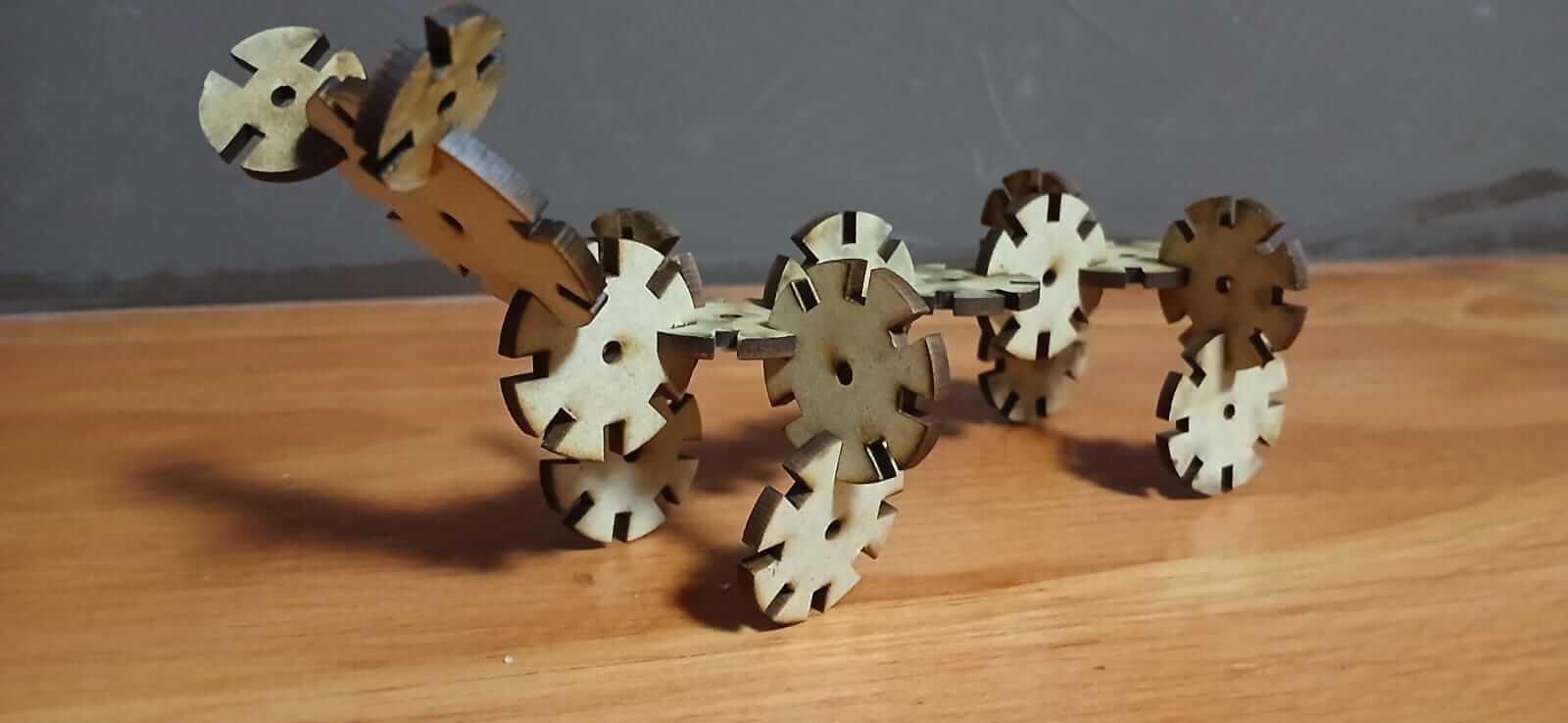
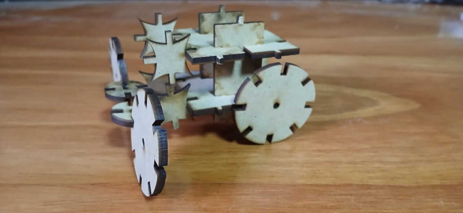
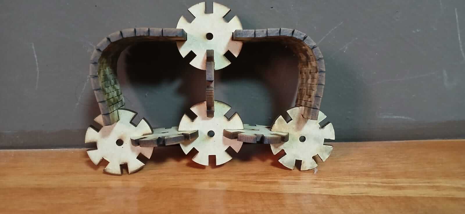
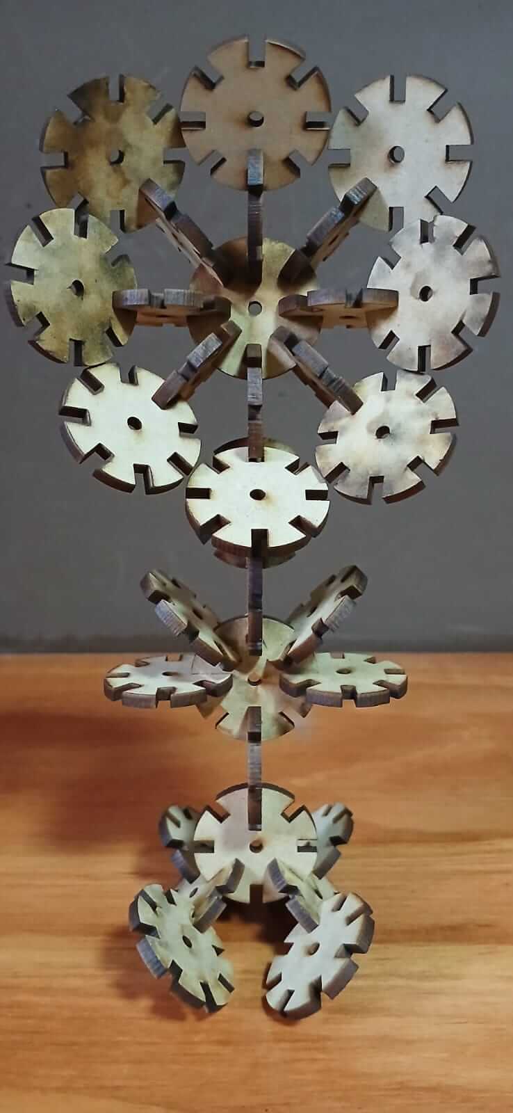
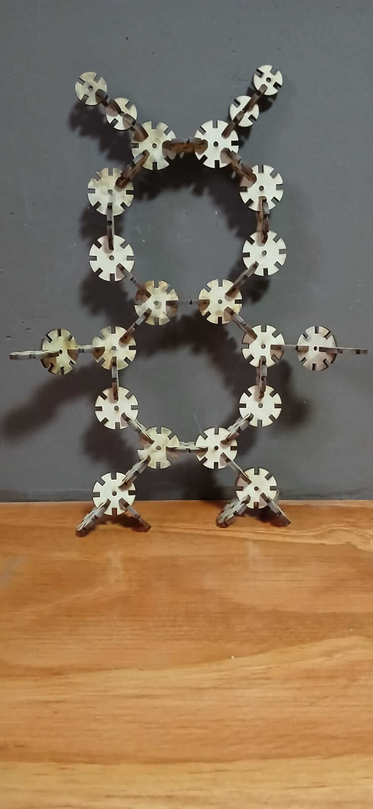
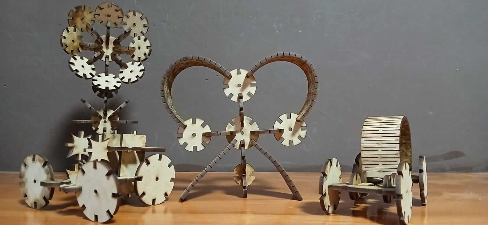
The number of pieces, sizes and shapes were designed so that my son could play with them.
Vinyl cutter
Before starting to use the vinyl cutter, it is necessary to already have a design. In my case, I look for an image without copyright. ( Link1 or Link2 ).
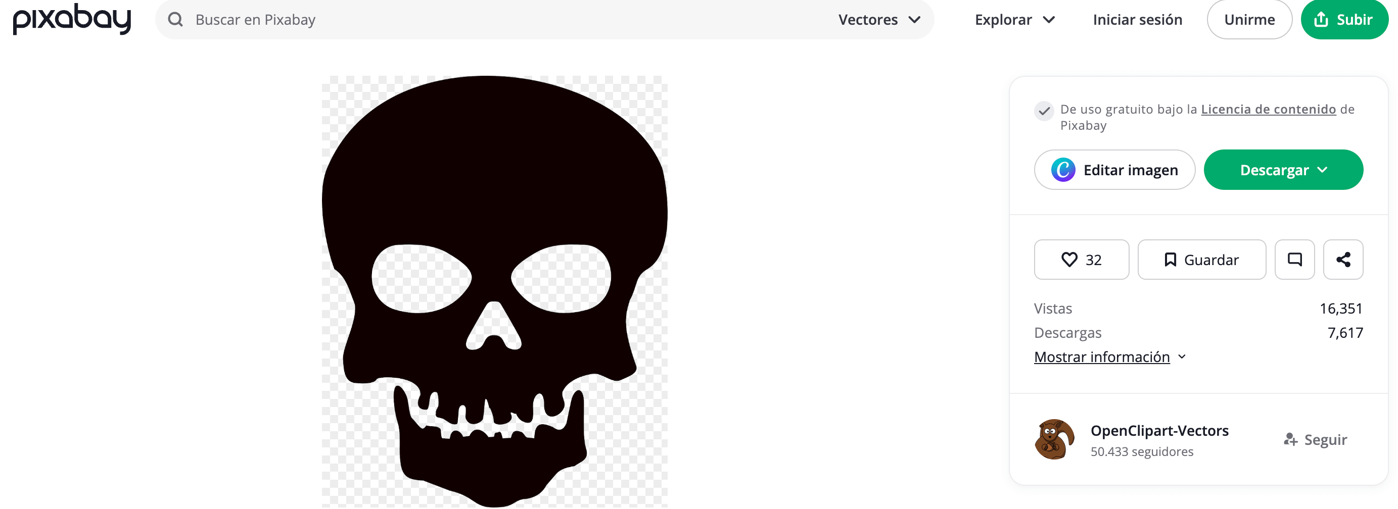
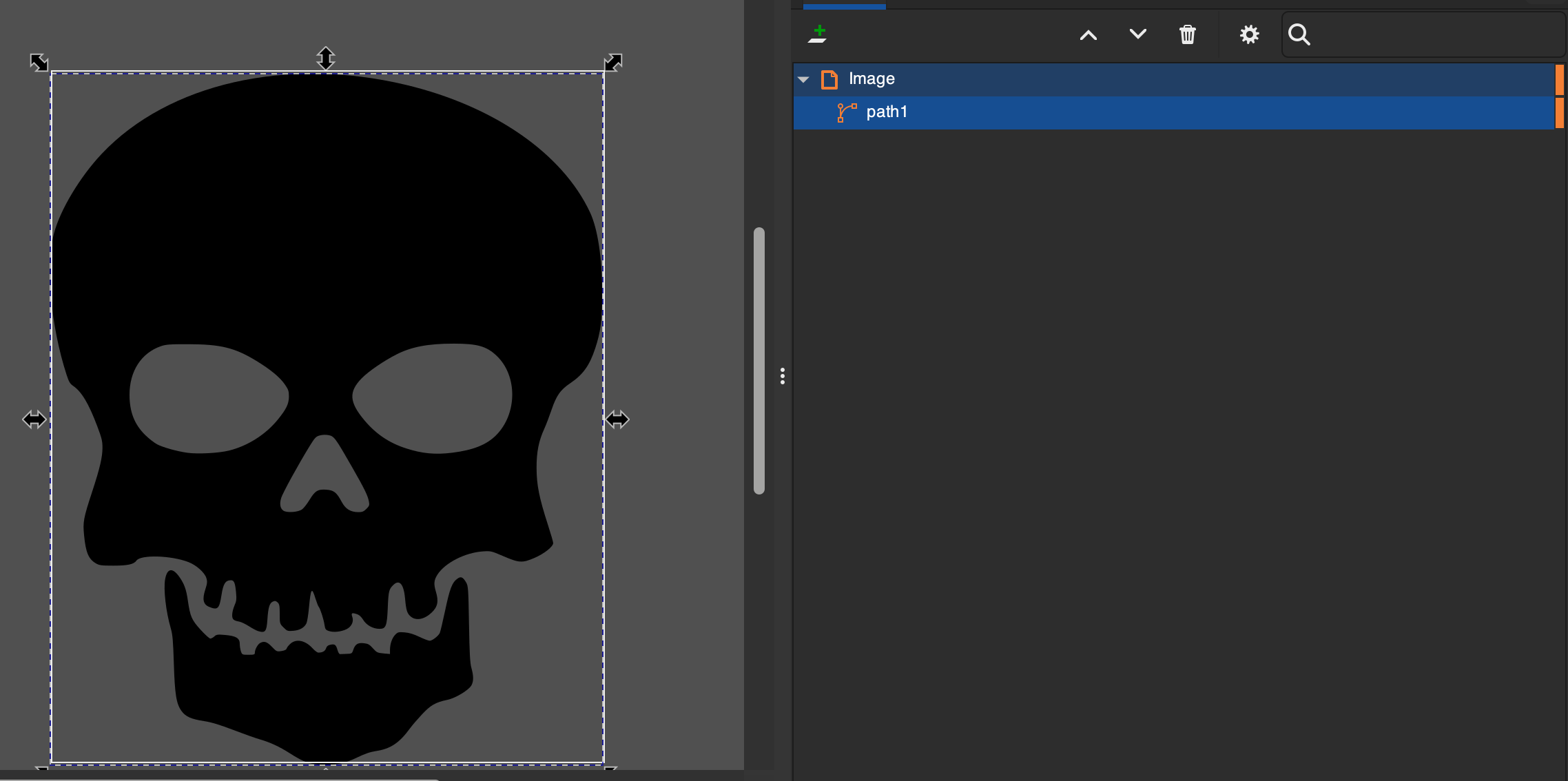
Once you have the image, it must be vectorized since the cutter can only cut vectorized images, so we use "Inkscape" for this purpose, you can also search for an image in "DXF" format.
In the following link you can download the image.
Skull.svg
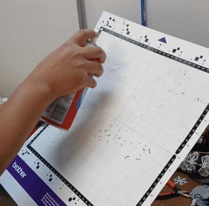
The first step is to clean the work area to avoid residue from previous work.
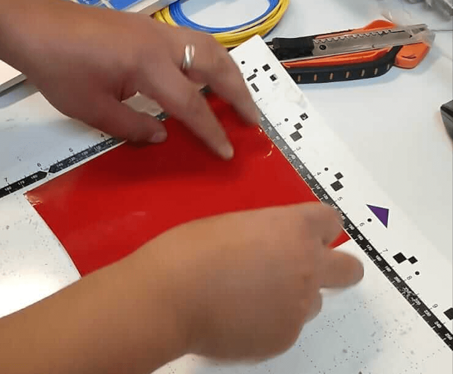
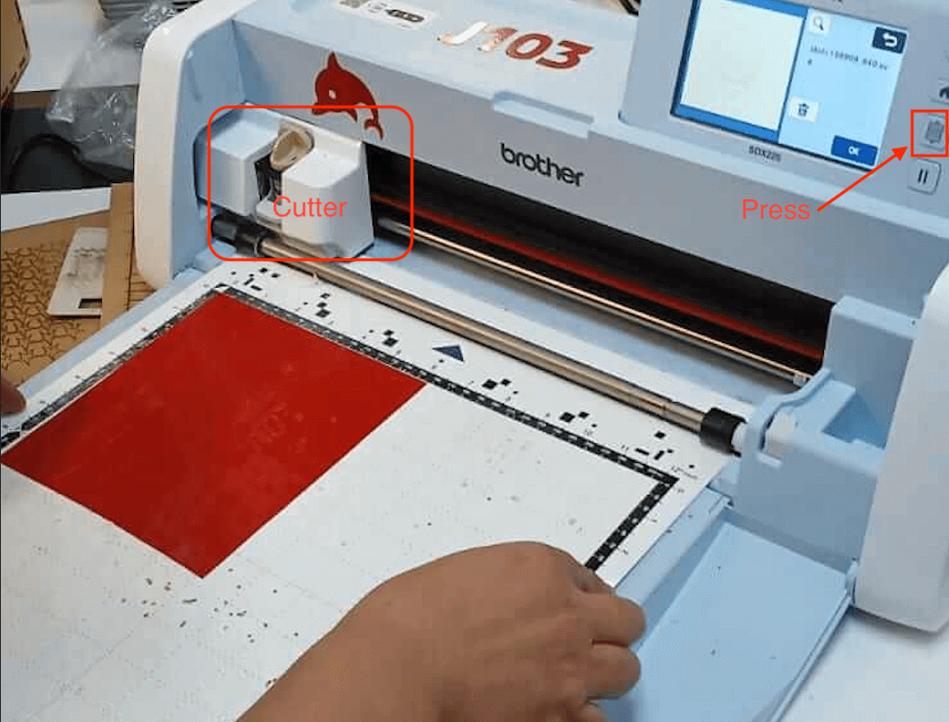
Once clean, spray glue is applied to the mat to place the vinyl; Then we place the vinyl in the upper left corner, ensuring that it is aligned with the grid of the bed. Now, we must introduce the mat into the machine, for this it is necessary to press the button shown in the last image, the machine will automatically pull the sheet and align it. It is important to note that there are two types of heads, one is for cutting (blade) and the other for labeling (colors), in our case we will use the one for cutting. The vinyl cutter used is the "brother SDX225" and in the following "Link" you can find the manual.
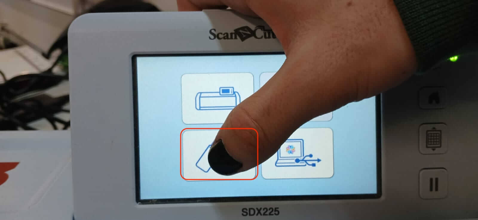
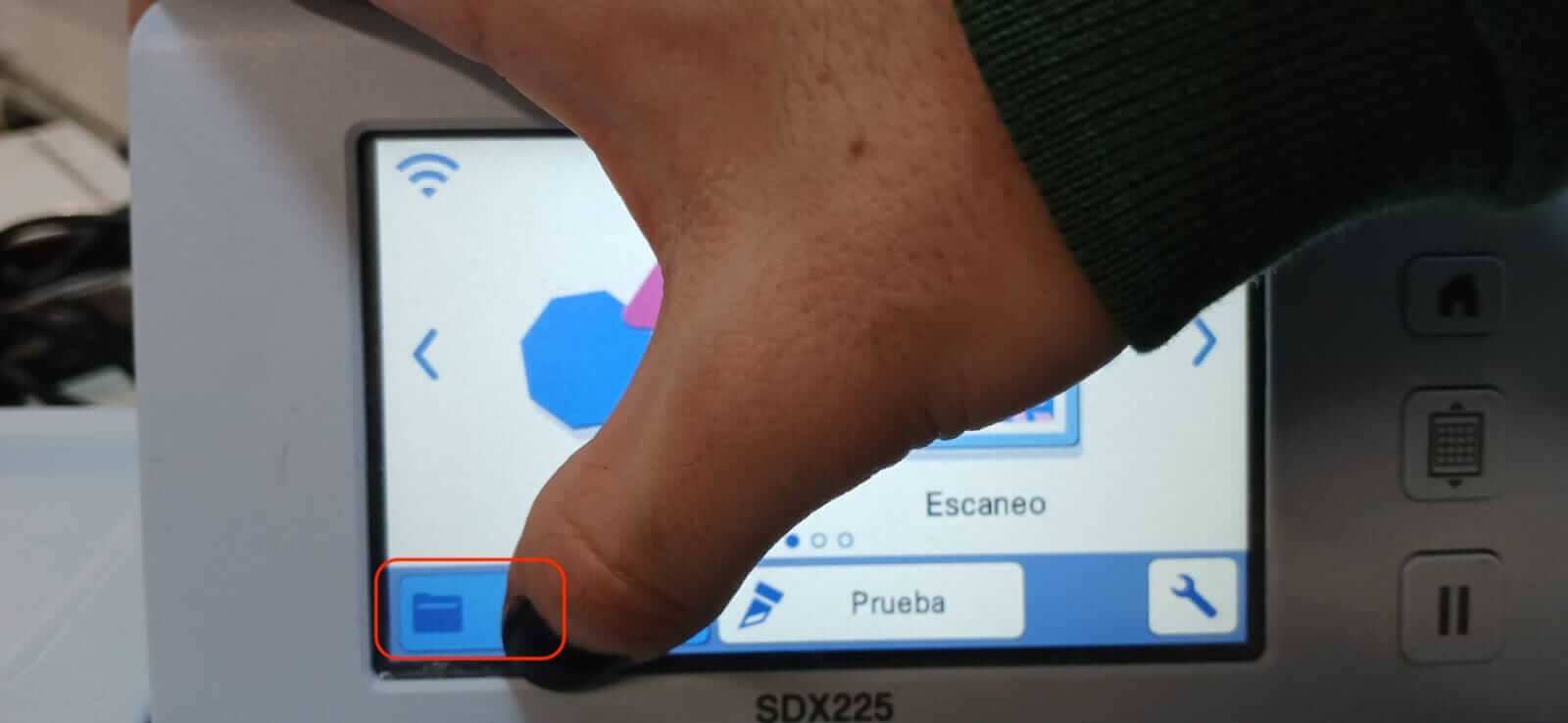
To make the cut, we look for the image of interest, to do this we enter our USB memory to locate it. When doing this, the cutter shows us a preview of the image. If we have a non-vectorized image, the cutter will flag an error, and it will be necessary to make the corresponding edits in our image editor ("Inkscape") and we will have to repeat the previous steps.
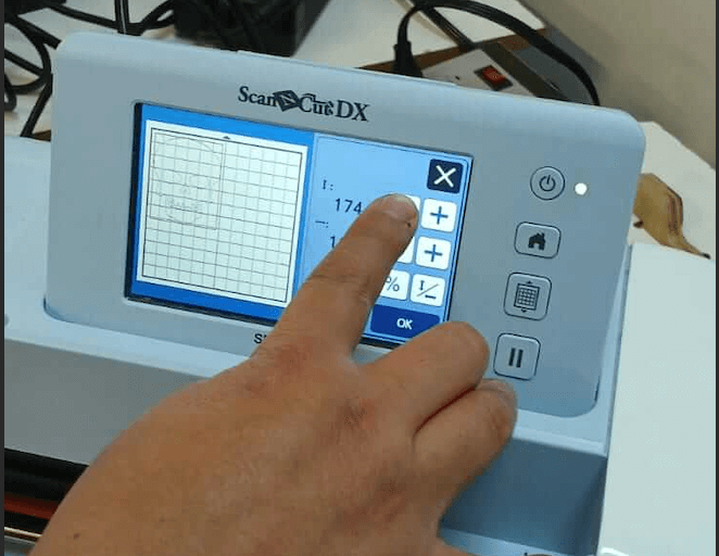
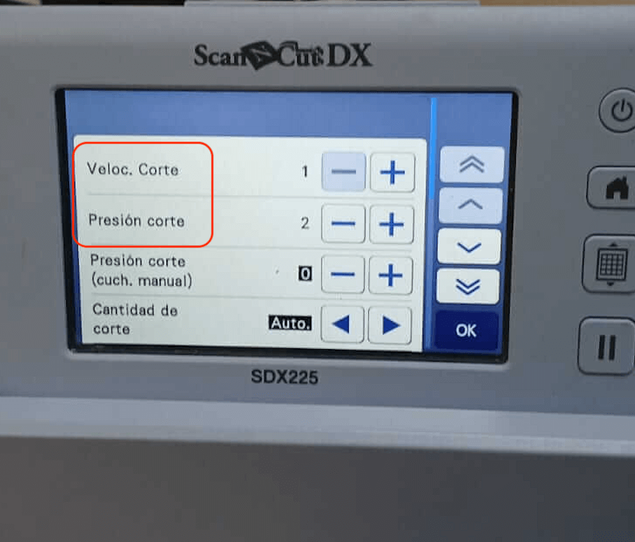
In the adjustment menu, we can see where our drawing is located to relocate it to the position we want (where we placed the vinyl). The image will appear on the screen with the mat grid and must match the physical grid (same number of frames). In case the image goes outside the margins, we can scale it by pressing the button as shown in the image, with this we can see how the image increases or reduces, if we agree with the changes we click "OK". Afterwards we must select the process to be carried out (in our case it is cutting), however, before starting the parameters "Cutting speed" and "cutting pressure" must be verified. If the details of the image are very fine, the recommendation is that the cutting speed be slow.
Once the above is done, press "OK" and then "start". The machine will start cutting.
In the figure below you can see the comparison between the real image and the vinyl cut.


Finally, we placed a special paper where the vinyl would be placed, and ready to paste wherever we wanted.
Learning outcome
This week we learned the importance of parameterization when designing pieces so that they can be scaled,
the importance of the images being vectorized so that they can be read by the vinyl cutter.
Another important point is safety measures when using the laser cutter, since the laser cannot be seen
and it can be dangerous if handled incorrectly.
Acknowledgment
Thanks to Apolinar Velazquez and Jose Carlos Matanzo, for helping me use the cutters.