GIMP
GIMP is an
Open
Source Image Editor. It is available for GNU/Linux, macOS, Windows and
more operating systems.
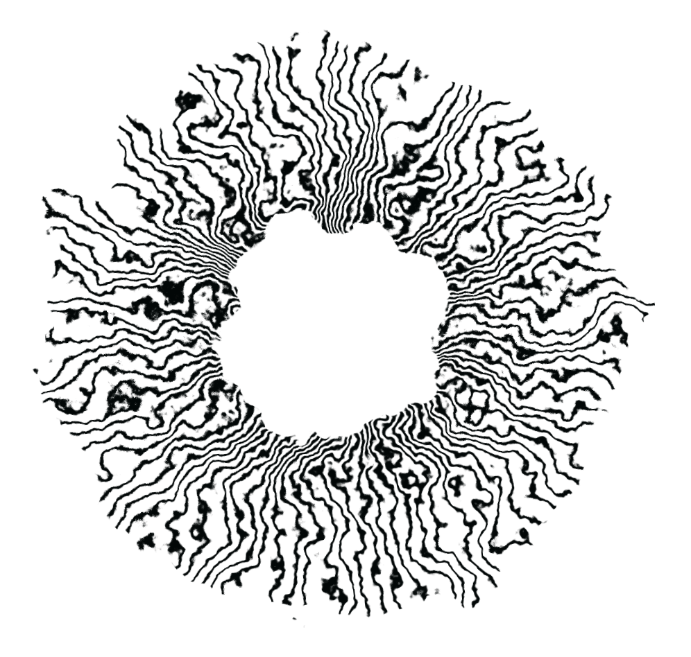
It was decided to work with GIMP, since we were looking
to edit the image of eyebrows .
The feature of GIMP is that the workflow is similar to "photoshop".
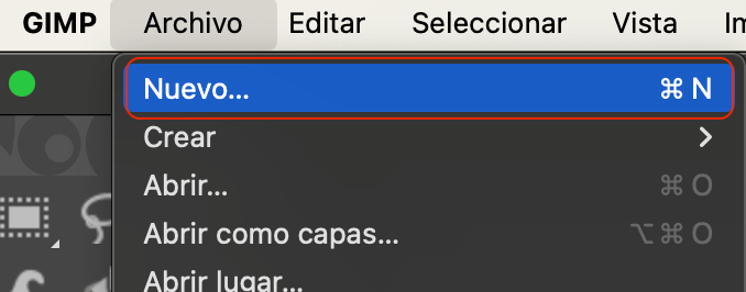
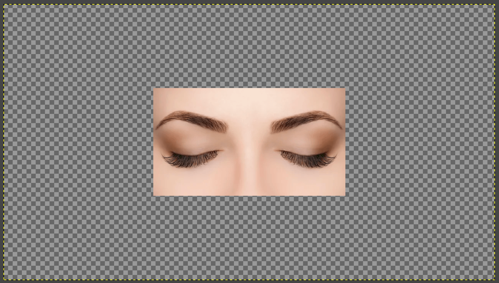
To begin, we open a new file "⌘N" (macOS users), which displays a new window where
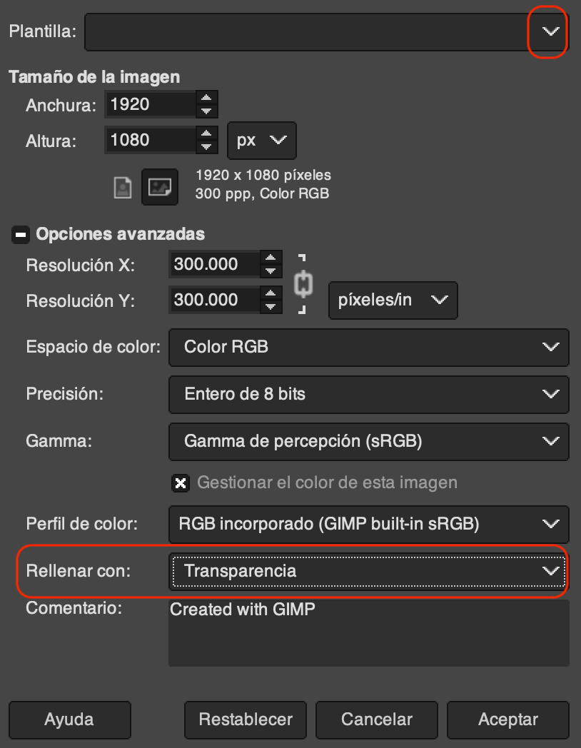
we must describe the characteristics of the work area such as the size of the
image (width and height) or simply select one of the templates suggested. Another
important point is "Fill with" where it is suggested to place "Transparency",
since the aim is to leave only the eyebrows without any background.
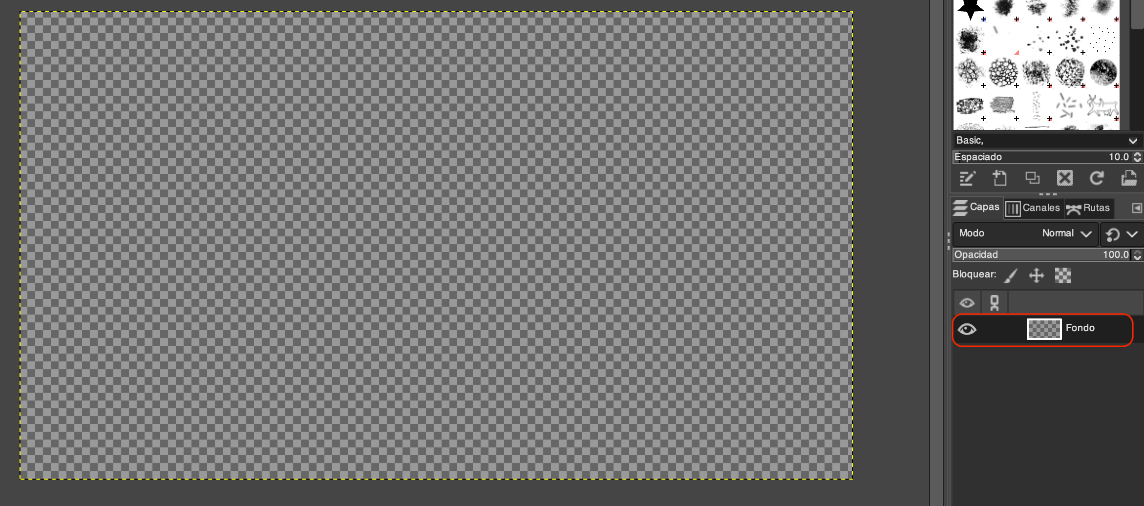
Performing the previous steps creates a new layer with a transparent background.
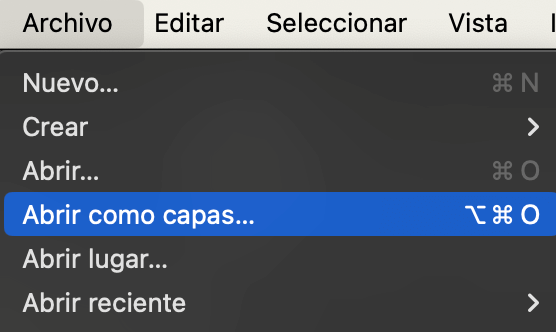
Now, we need to insert an image, for that we go to the menu "File - Open as
layers" or simply "⌥⌘O", it is done this way to separate the background from
the image.
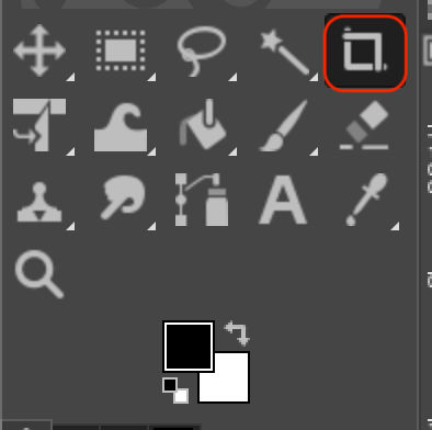
In our case, the image was smaller than the work area, so we can use the
"crop tool (⇧C)" to adjust to the size of our image and with "enter" the cut is made.
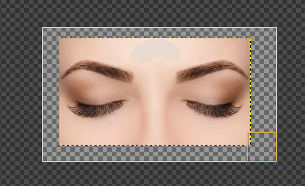
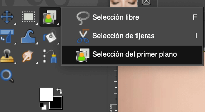
Now, we need to select the eyebrows, for that we must use the selection tool,
although there are many tools, for this task the "Foreground Selection" was chosen.
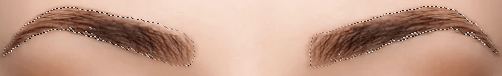
Once the tool is selected, we continue to contour the eyebrow. When the contour has
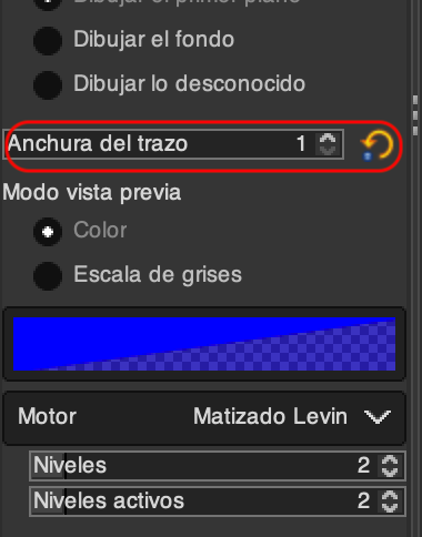
been made, we can notice that the selection is not perfect, however, one of the
characteristics of the tool is that with a pencil you can select the eyebrow tones
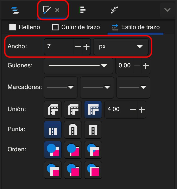
that you want to include. With the pencil you can choose the "stroke width" option
and make the selection finer.

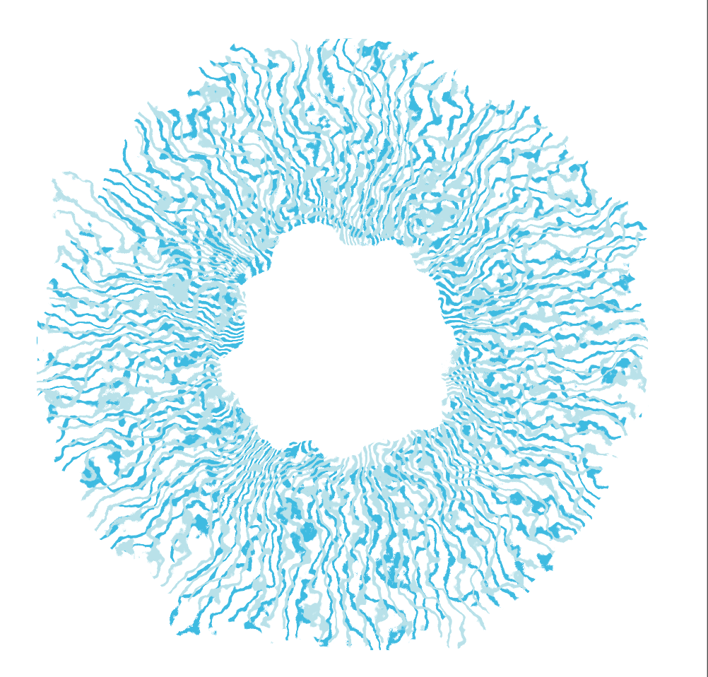
Once we achieve the desired contour, press "enter" and the selection will be made.
To finish, invert the selection in the "Select - Invert" menu or using "⌘I".
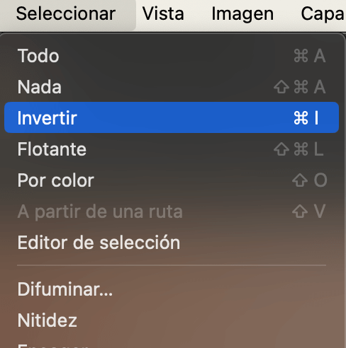
Once the selection is inverted, click delete and only the eyebrows are obtained.
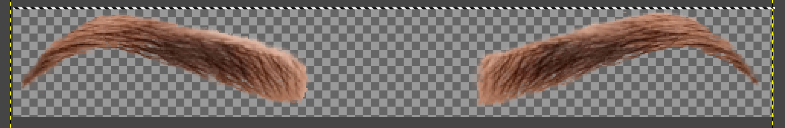
In the following link you can download the image.
eyebrow.xcf
3d design
The characteristic of 3D design is that it allows objects to be represented in
3 dimensions (length, width and height). In the following sections, two tools
will be used in 3D design ("Onshape" and "SolidWorks"), in which pieces that
could be part of the "final project" will be made.
Onshape
Onshape is "not open source" software, however, the fact that you do not need
to install any software on your computer makes it a very interesting option
since you can work from any computer just by having an active account and an
internet connection.
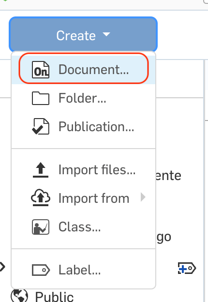
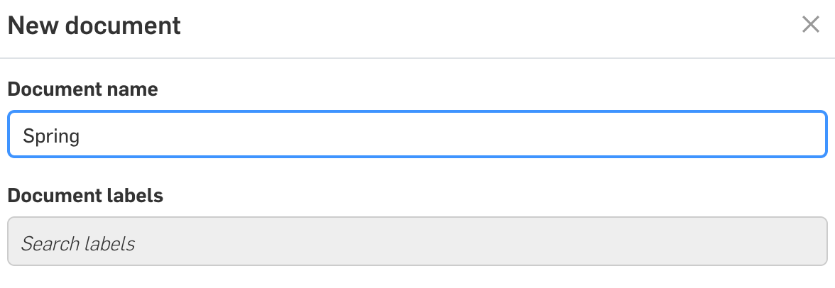
To begin, we enter the following " Onshape link " , where
we register. Once inside, we select "Create" and "Document...” and write a
representative name.
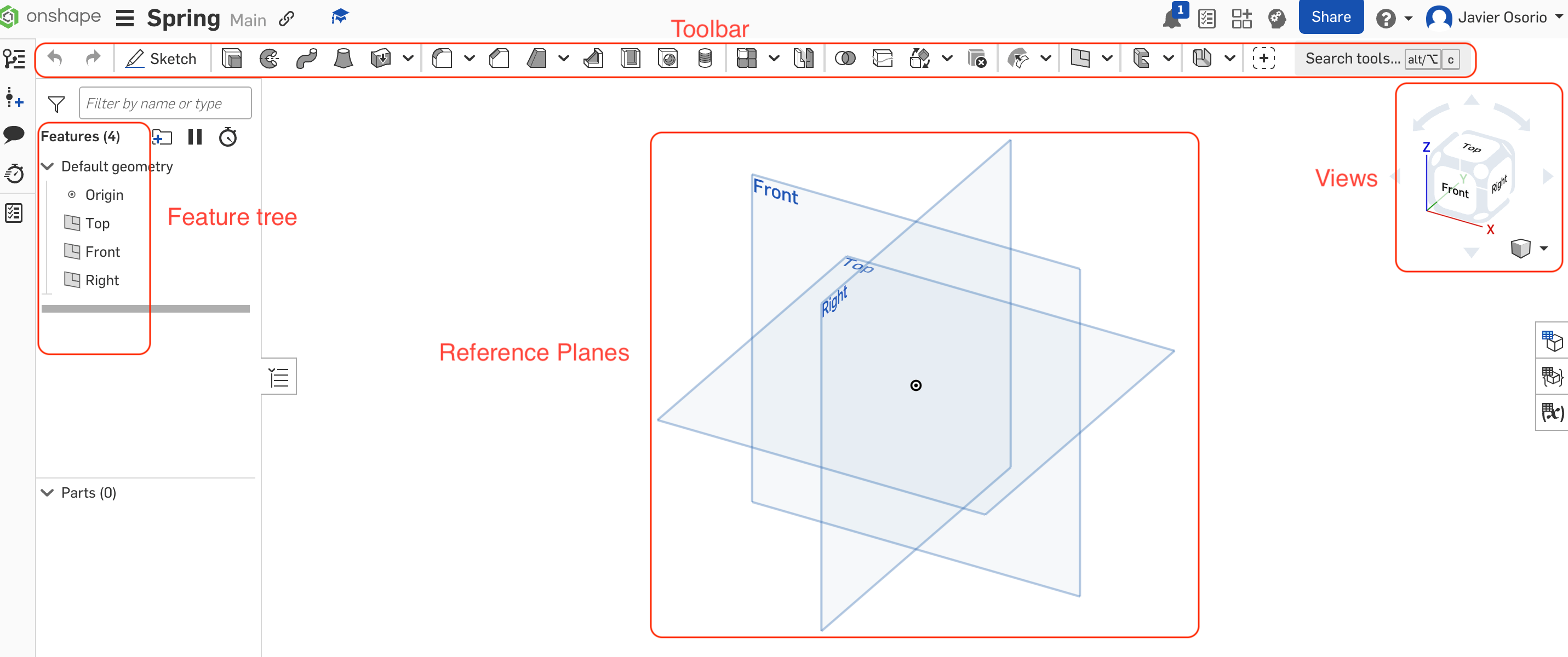
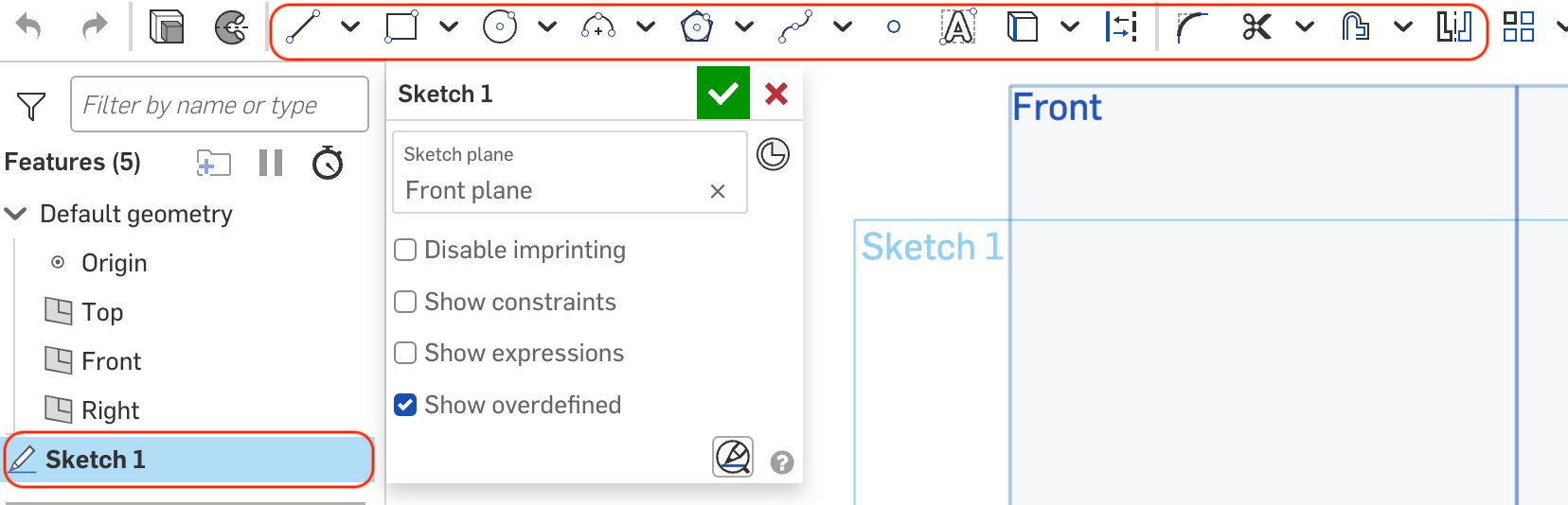
The above opens our work area; In the image below you can see the different
elements that make it up.
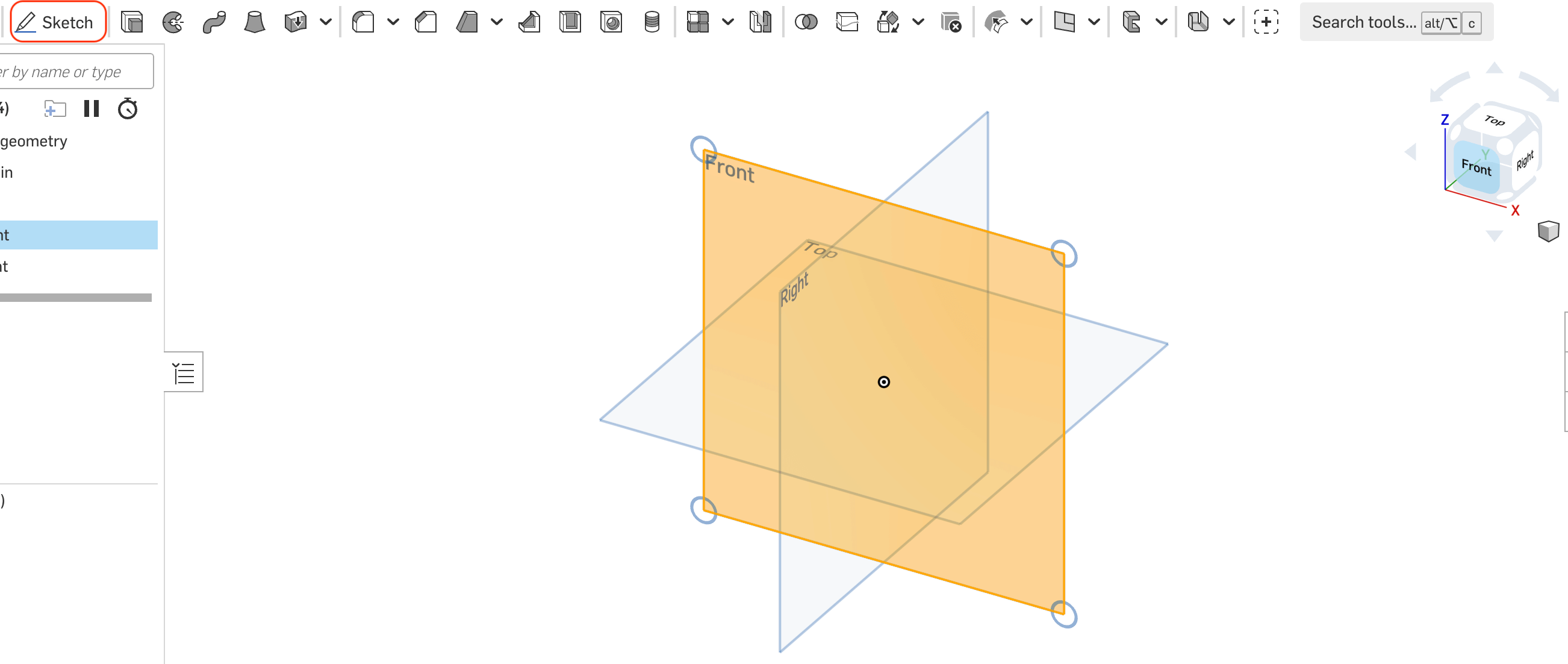
We select a plane (Front) with the help of our views and select "Sketch",
which opens the drawing tools.
Before starting to use the tool, it should be emphasized that following the objectives
of the proposed project (animatronic), we want to design a contour of springs around
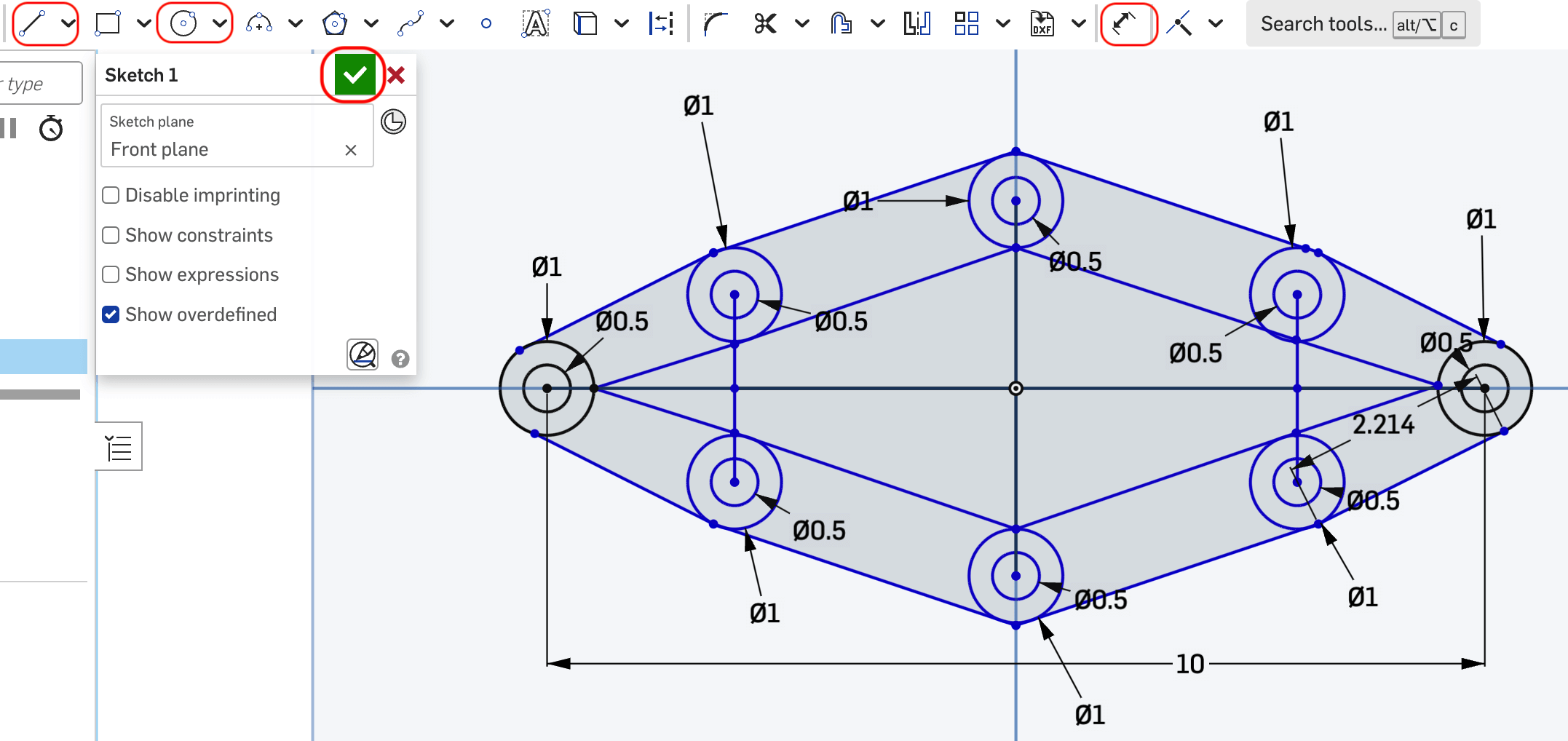
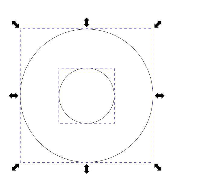
the mouth that allow to emulate the natural movement of the lips. For this, a first design is
made, which consists of drawing the contour of the lips, placing concentric circles,
which will serve to fix the structure created with the mandible (corner of the lips),
and with servomotors that will be used to generate the movement.
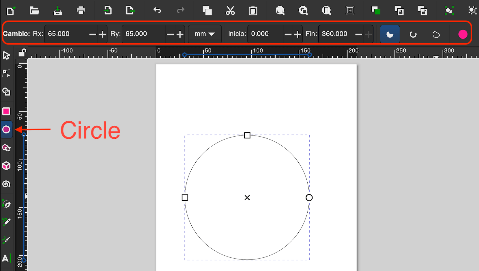
To create the lines, press “Line” or “L”, and to create the circles "Center point
circle" or "c". Finally, to have the correct dimensions, it is important to use the
"Dimension" or "d" tool which helps us dimension.
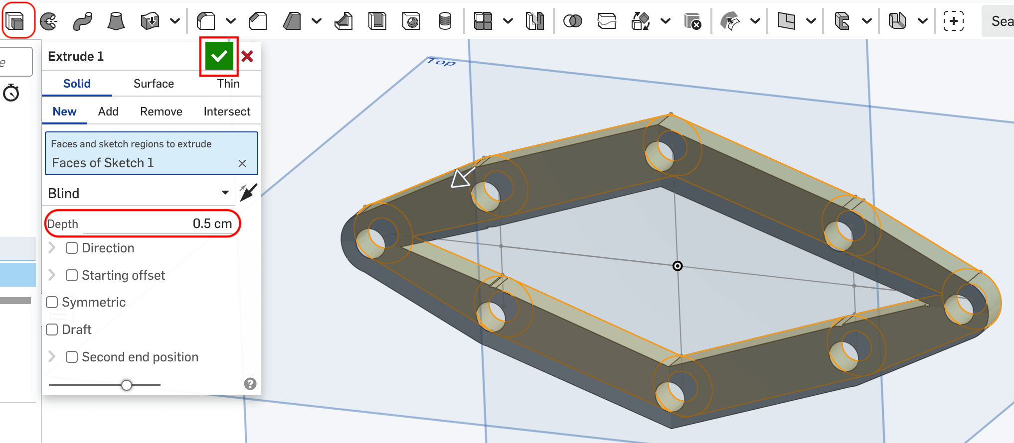
Once the periphery is made, it is necessary to give it depth, for this we select
"Extrude (shift+e)", which opens a new window where it allows us to select the areas
we want to extrude and their depth. Doing this shows the changes automatically.
If we agree, we accept the changes so that they apply.
The next step would be to make cuts that allow the structure to work like a spring,
for that we select the view in which we are working "Front", once the view is selected,
click the "Sketch" option and with "Line" we make triangles. When all the triangles are
ready, we click accept.

The final step is to remove the triangles that were sketched, so
"Extrude" is used again. In the dialog box that opens we select
"Remove", we indicate the depth that will be removed from the material, and we must
select all the places that we want to remove, ensuring that the contours are completely
closed.
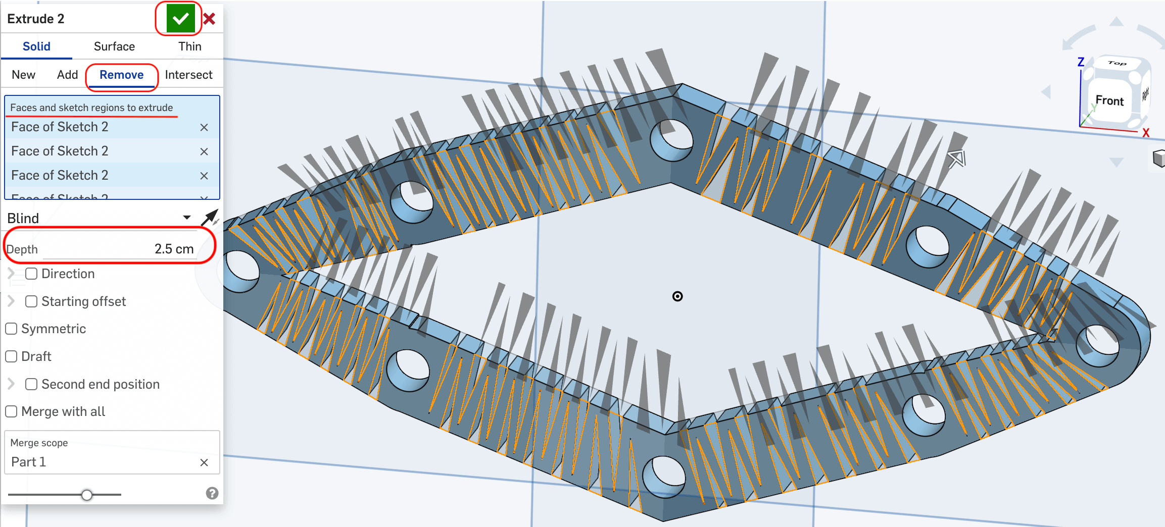
The final piece is shown below.
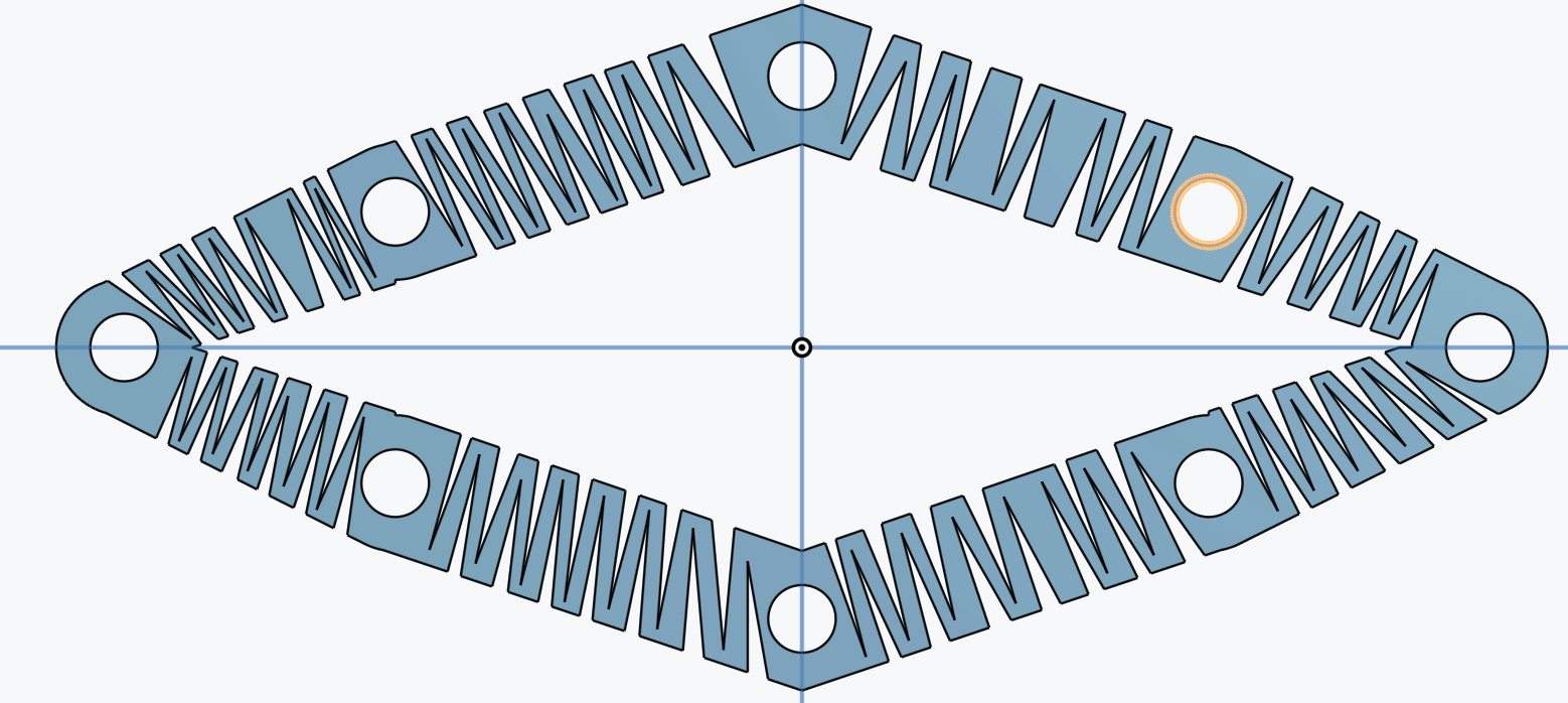
In the following link you can see the file.
Spring
Onshape is an intuitive tool, with a good workflow and portable; The only
negative point is that it depends on a good internet connection.
SolidWorks
SolidWorks is one of the most powerful and most popular tools in engineering
when creating 3D CAD designs. SolidWorks is not only used to make designs, but it
also allows you to make:
- Simulations
- Assemblies
- Animations
- Render
SolidWorks will be an essential tool when carrying out the "final project",
since all the mechanical parts and pieces will be designed with this tool.
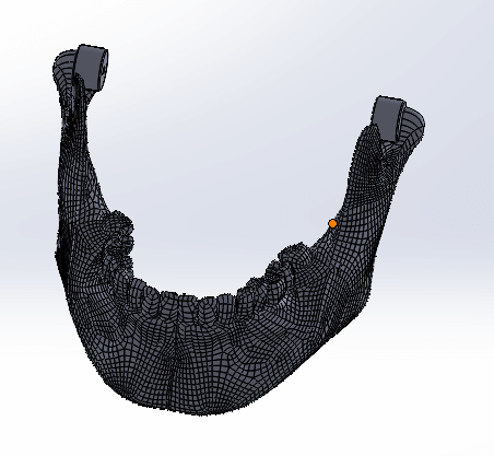
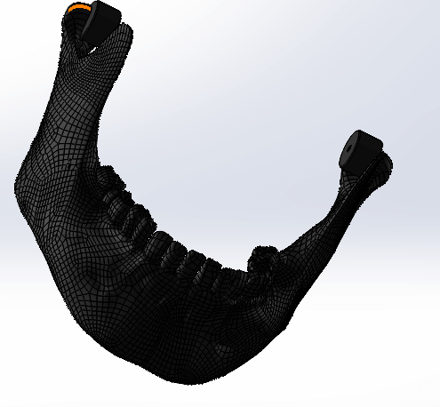
The objective of this section is to render a part, for that the model of a jaw
is downloaded from the network.
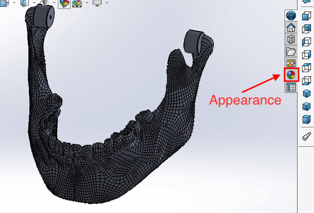
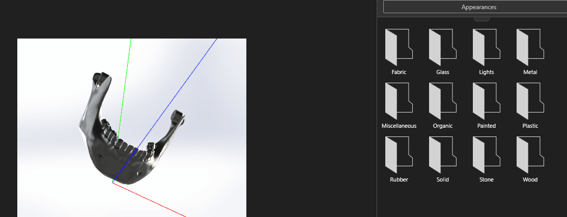
We will select "appearance" in case of giving color to the object so that it looks more realistic.
This opens a new window with different appearances that can be worked with.
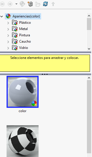
A material is selected, and the appearance of the piece is chosen. That
selection, without releasing it, is dragged to the area of the piece where you
want to provide those characteristics. When you release on the piece, a new menu
is displayed, in which you must select where you want the changes to be made (in the
entire material or in certain parts of it).
Once the above is done, the piece has the selected appearance.
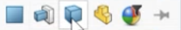
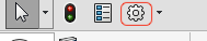
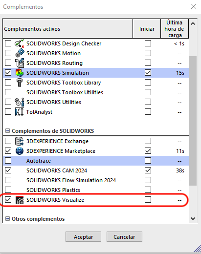
The next step is to render the piece, for that we must have "Visualize" in
our bar, if it does not appear, it is necessary to enter the Options menu and
select "Add - Ins". This displays a new window in which we can select
"SOLIDWORKS Visualize".
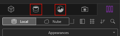
Now the "Visualize" tab should appear in the bar, we select it and click
on "Export simple".
This should open the renderer, in which our piece will be displayed, with green,
blue and red lines that indicate the orientation in the "x", "y" and "z" axes.
To make the piece look realistic, you can change the type of lighting and
modify the characteristics of the material that was previously placed in SolidWorks.
Once all the changes have been made and the piece has been placed in the desired
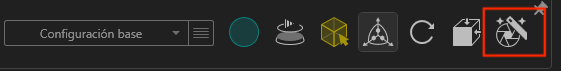
orientation, the next thing is to render the piece. To do this, press the icon
shown in the figure.
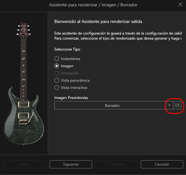
The above opens the "Render Wizard", where we must select the type of rendering and
its quality, when finished we press "Next". Then it opens "Media", where it asks us
for the "Format" of the image. The following options are "Size" which asks us for
the size of the image and resolution, "Quality" which asks us for the quality of
the "Render", and finally "Output", in which we must give a name and the location
where it will be will save the Render.
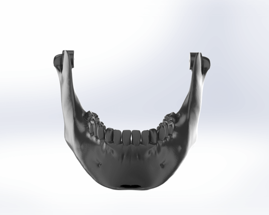
By doing all the previous steps, the piece has been rendered. All that remains
is to save it and the result is shown below.
SolidWorks is a very powerful tool, with a user-friendly workflow. One of the
advantages of working with SolidWorks is that there is a lot of information and
tutorials on the Internet, which makes it easier to implement what you want to design.
Image and video compression
Image
One of the easiest ways to reduce the size of images is through the following
" link
"page.
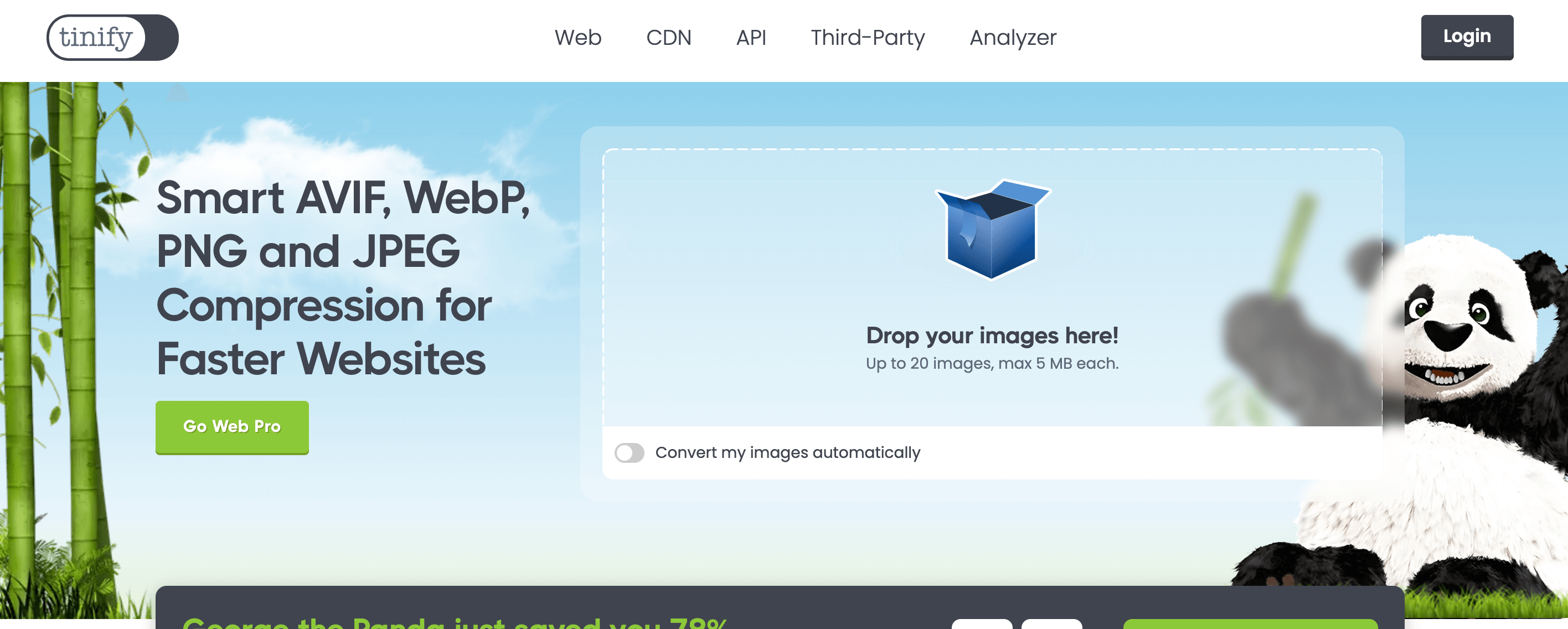
When the images have been placed, the program begins to compress them automatically,
making reductions in some cases above "80%".
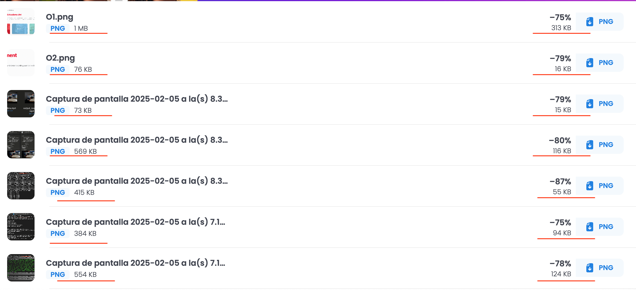
If all the images have been compressed, press " Download all images",
which downloads all the images in a ".zip"
Video
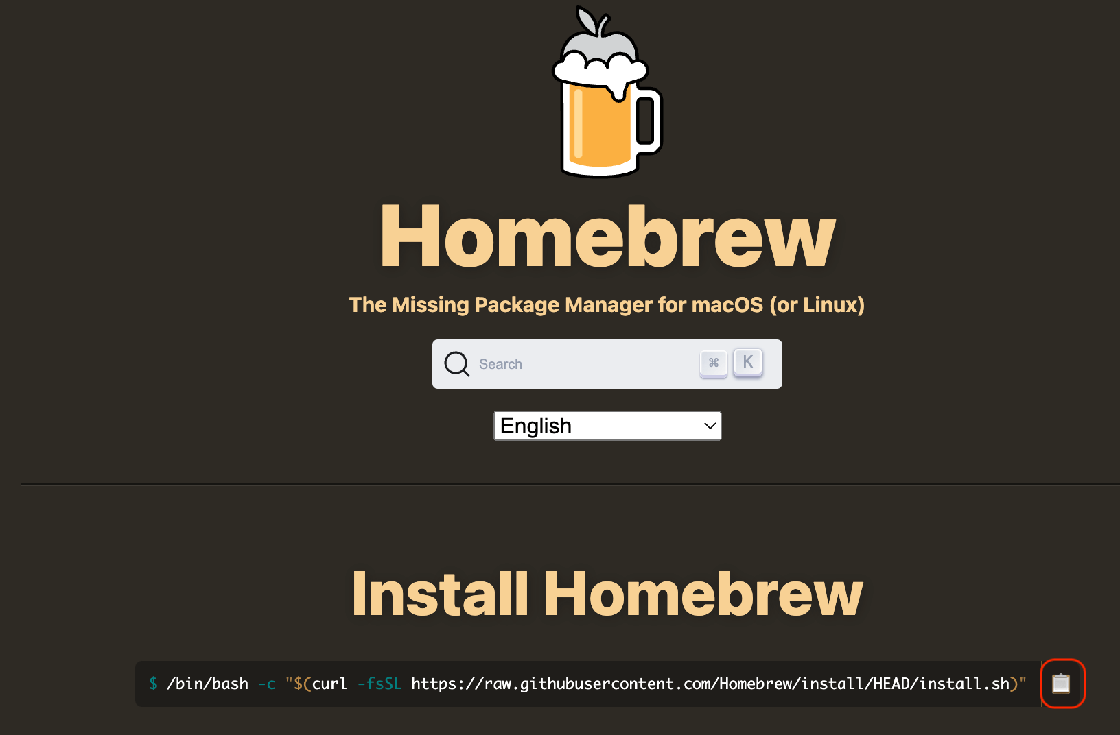
In the case of the macOS operating system, it is necessary to install
"Homebrew". For that it is necessary to open the following
link , where
you must press the button shown in the image and paste it into the terminal.
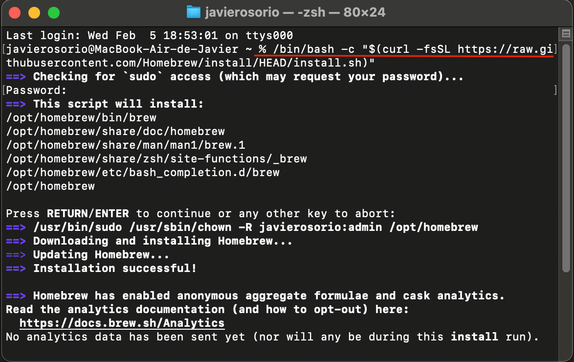
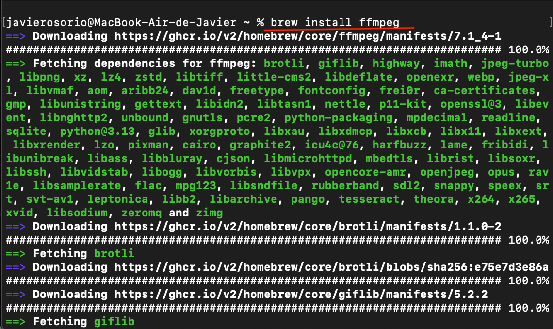
When the thermal installation is carried out, it is necessary to execute the
following instructions in the terminal.
- brew install ffmpeg
- ffmpeg -version
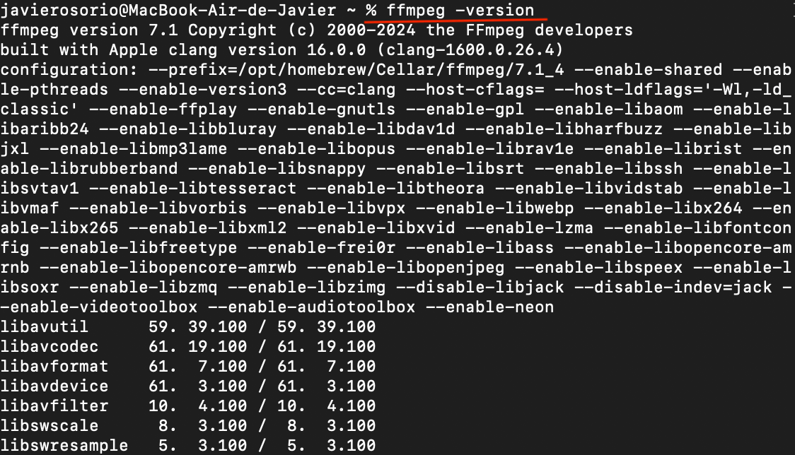
When you finish executing the instructions, it is now possible to perform video
compressions. Below are some examples of compression instructions.
- Compress video ffmpeg -i input.mp4 -vcodec libx264 -crf 28 output.mp4
- Compresses video and reduces resolution ffmpeg -i video.mov -vf scale=1280:720 -vcodec libx264 -crf 28 output_720p.mp4
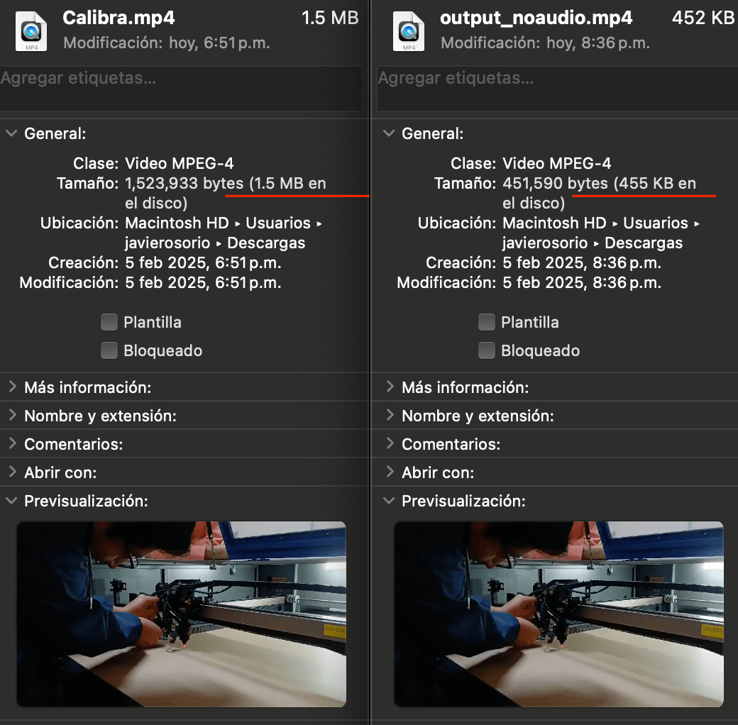
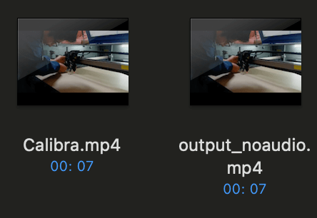
- Compresses the video and removes the audio ffmpeg -i video.mov -vcodec libx264 -crf 28 -an output_noaudio.mp4
- Increase video speed and removes the audio ffmpeg -i video.mov -r 16 -an -filter:v "setpts=0.25*PTS" salida.mp4
In the following link you can see a tutorial in Spanish with
explanations of the different commands.
Tutorial in spanish
Transloadit
HTML5 MP4 ffmpeg encoding
Learning outcome
This week we learned the use of 2D and 3D design tools, emphasizing
the differences between them, their scope and their different applications.
On the other hand, image and video compression methods were used, such as
websites and “Homebrew” through “ terminal”, respectively.
