Computer Controlled Machining
Computer-controlled machining involves using CNC machines to cut, mill, or shape materials based on digital instructions. These machines follow G-code to move the tool with high precision, making it ideal for producing reliable parts across various materials. For this assigment, my goal is to create a custom welding station table for my home workshop. The workflow involves designing in CAD software, preparing machining paths in CAM software (VCarve), and finally cutting the table parts using the CNC machine Asia Robótica Router. To ensure correct use of the routers in the FabLab, the group assignment provides detailed guidance.
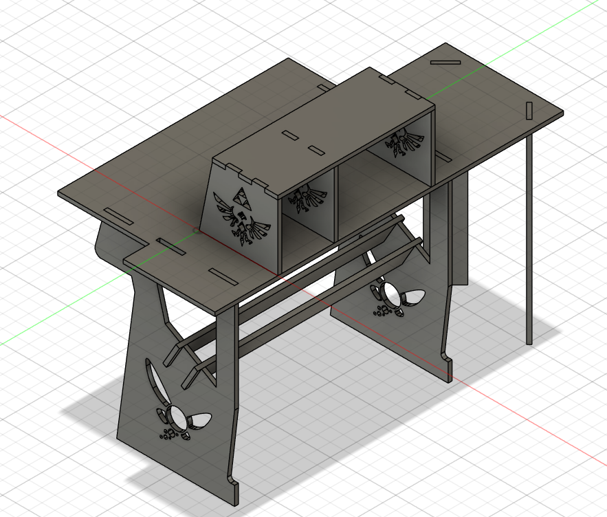
Desk/welding station desing
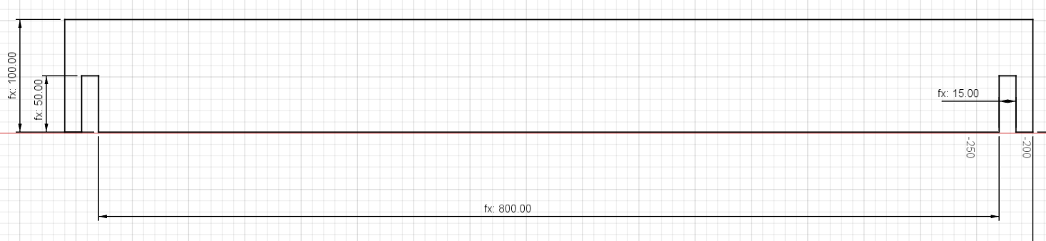
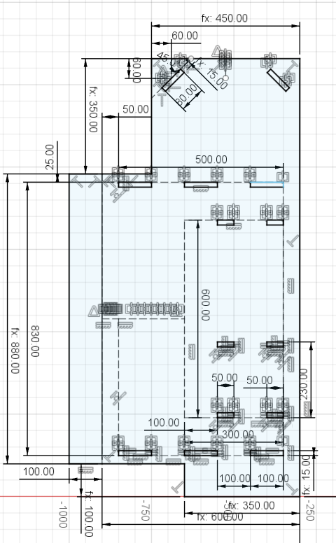
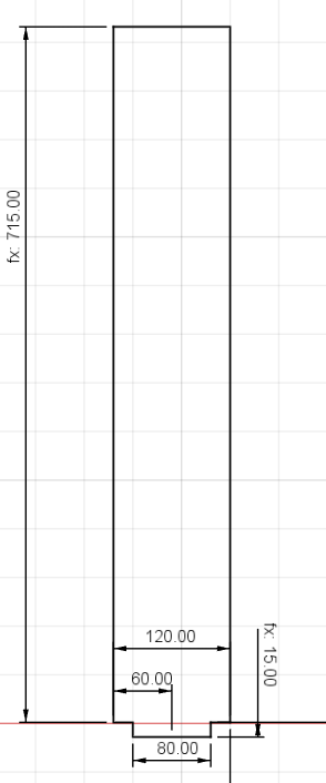
Before preparing the toolpaths for machining, I developed the complete design of the desk in Fusion 360. Due to time constraints and the need to make adjustments incrementally, I defined a set of user parameters from the beginning. These parameters allowed me to keep the key dimensions organized and easily adjustable across the different sketches and components.
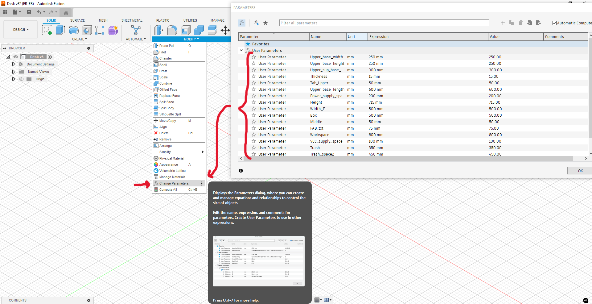
Figure 1: Parameters used.
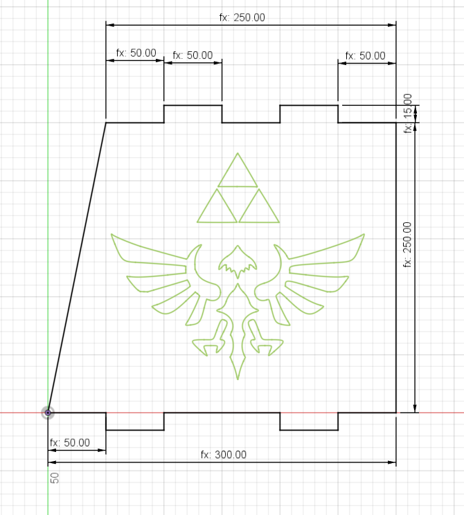
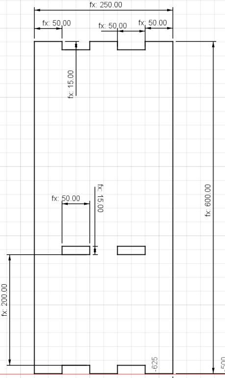
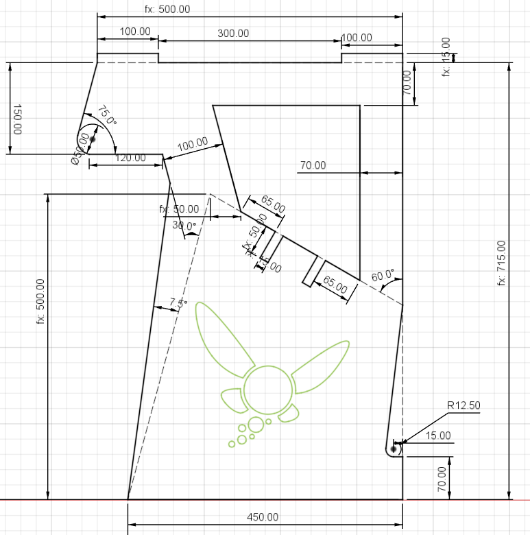
I kept the design fairly tight in terms of fit: I applied zero tolerance between interlocking parts. Although this meant the assembly would require some force, it guaranteed a solid, long-lasting structure once all parts were connected.
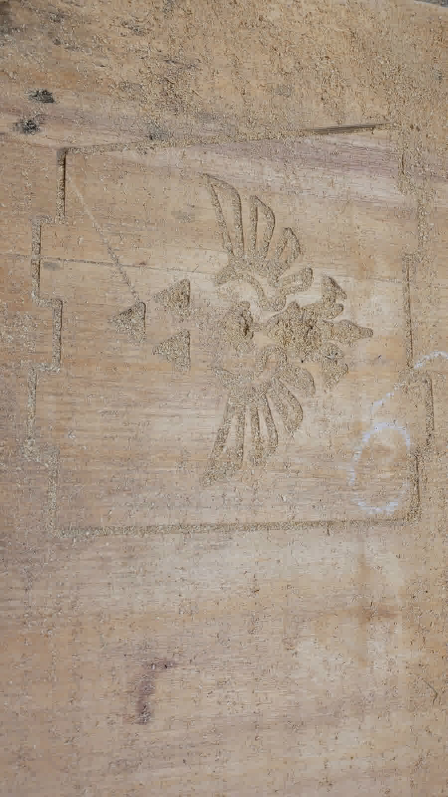
The pieces include side panels, internal braces, the main platform, and dedicated spaces for modules and trays. I also included engravings and as part some sketch profiles, this with the help of some SVG generated by myself in inkscape.
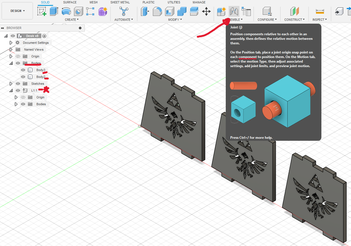
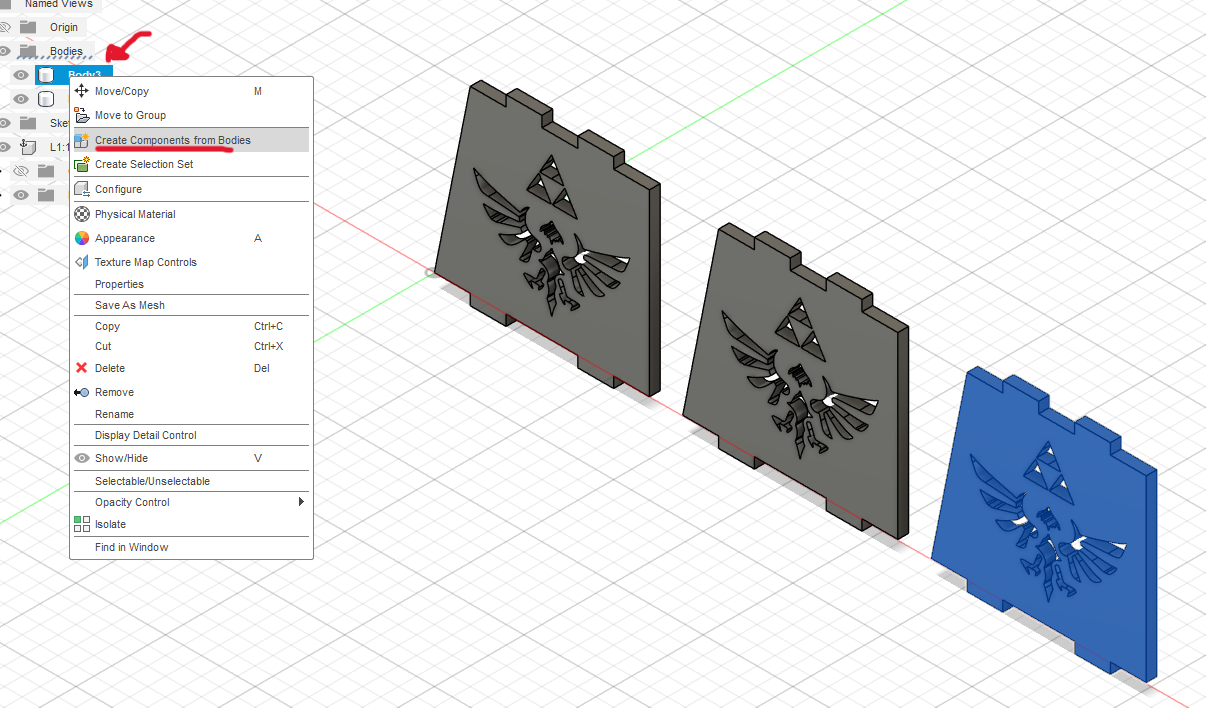
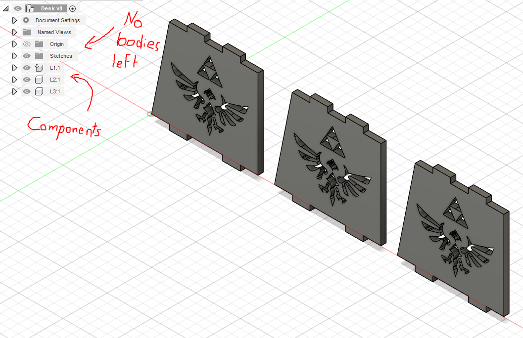
To verify the design and detect any potential issues before manufacturing, I created a full assembly using Fusion 360’s joint system. For this, I converted each body into individual components and then used the Joint feature to simulate how parts would fit together.
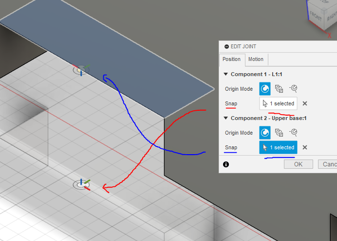
The process involved:
- Selecting precise snap points between components.
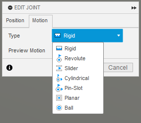
- Defining the typex of motion (in this case, I used Rigid joints) to lock their position relative to one another.
- Reviewing the assembled structure visually to check for unintended gaps, overlaps, or constraints.
The assembly seem pretty fine to me, so I decided to export all the sketches in DXF format.
CAM Preparation Using VCarve
Once the design is completed in CAD software, I export each component as a DXF file and import them into VCarve for machining preparation. Here are the essential steps:
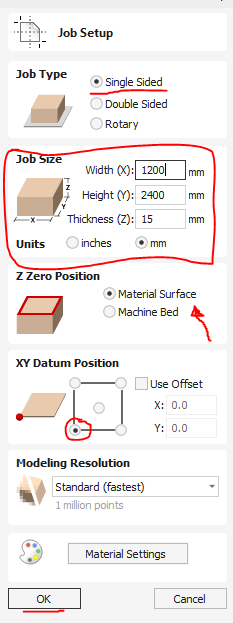
1. Project Initialization
First, I start by creating a new project in VCarve, specifying the dimensions of the plywood sheet I'm using (1220mm width x 2440mm length x 15mm thickness). I set the project's origin point to the bottom-left corner, making subsequent steps consistent and straightforward.
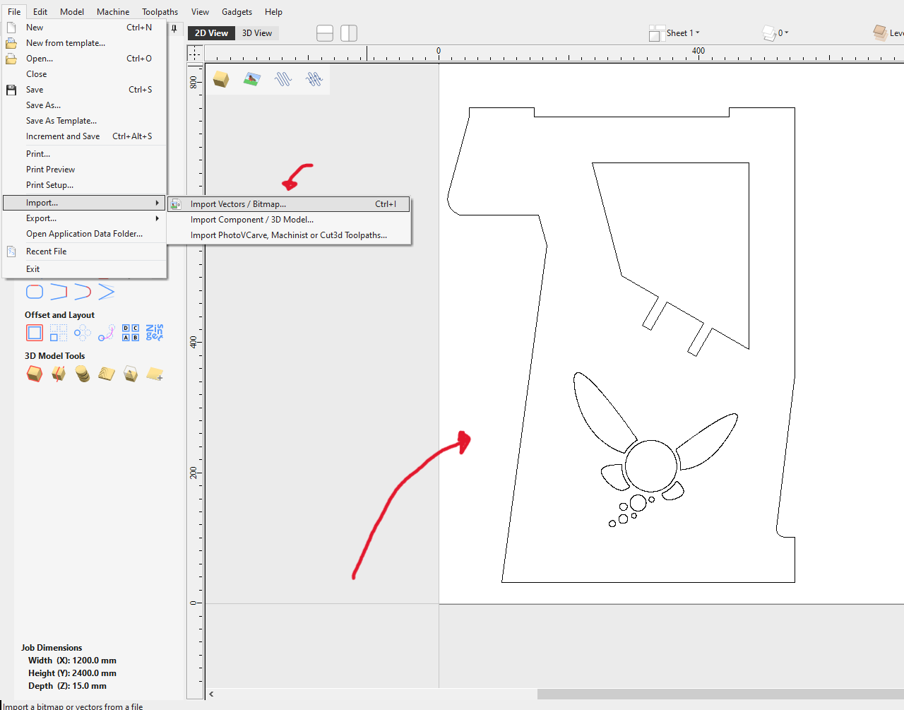
2. Vector Import and Alignment
Next, I import the previously created DXF files one by one, carefully positioning them within the workspace. I arrange each vector strategically, ensuring efficient use of material and avoiding interference during cutting.
3. Vector Editing and Joining
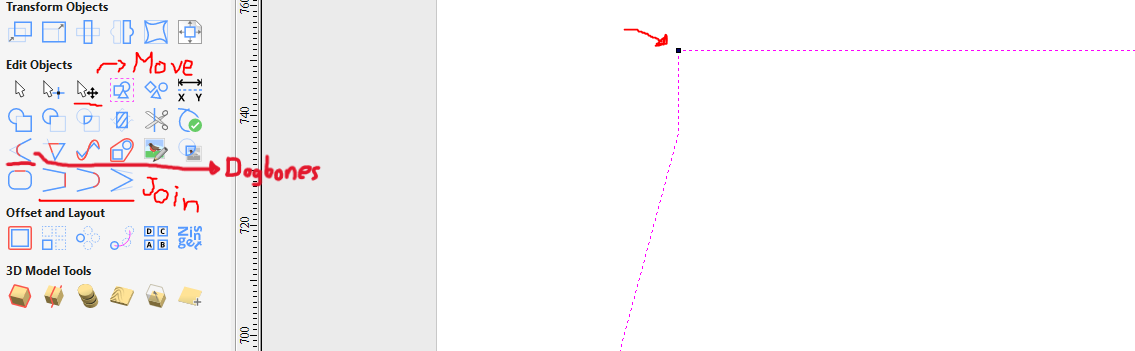
It’s essential to have closed vector paths for accurate machining, so I use the "Join Open Vectors" feature to create closed loops from any open lines. This step ensures the CNC will follow the intended paths accurately.
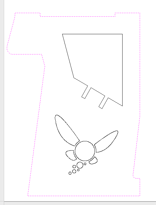
Figure 18: To properly join the vectors, first select the two vectors you wish to merge, then click on the previously mentioned operation to complete the process.
4. Dogbone Fillets Integration
When working with CNC milling, sharp internal corners can’t be cut perfectly due to the circular shape of the tool. The bit removes material in arcs, leaving rounded corners that can prevent interlocking parts from fitting properly.
To solve this, I add dogbone fillets—small circular extensions at the inner corners of joints. These adjustments compensate for the tool’s radius, allowing square-edged parts to slot together without interference. This ensures that all joints fit cleanly and assemble as intended.
Dogbones should be added only to interior corners of slots or holes where a square part needs to insert or lock in place. They are especially important in press-fit designs, structural joints, or assemblies that require high precision.
On the other hand, external corners do not require dogbones. Since the tool can freely move past the outer edge, it naturally forms clean, sharp corners without any fitting issues. I set the fillet radius to 3.175 mm, matching half the diameter of the 1/4” end mill used.
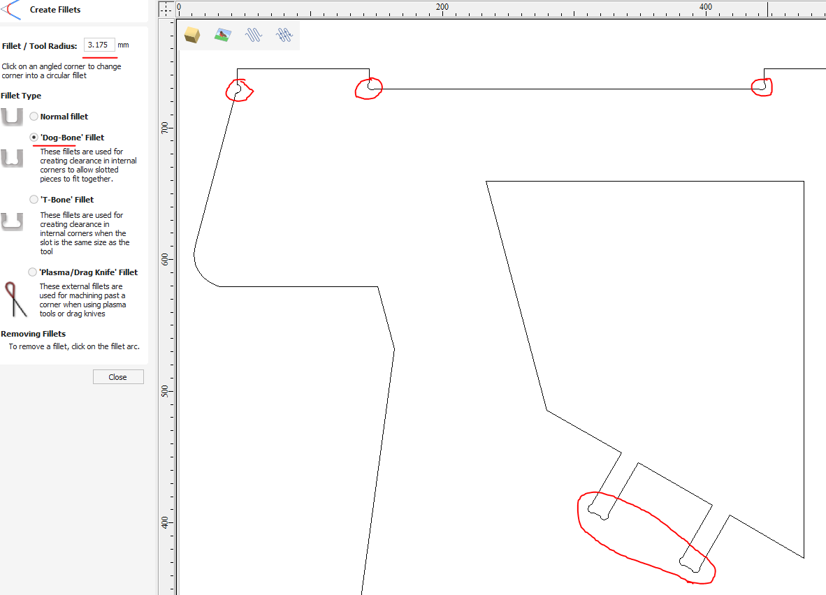
Figure 19: Dogbones.
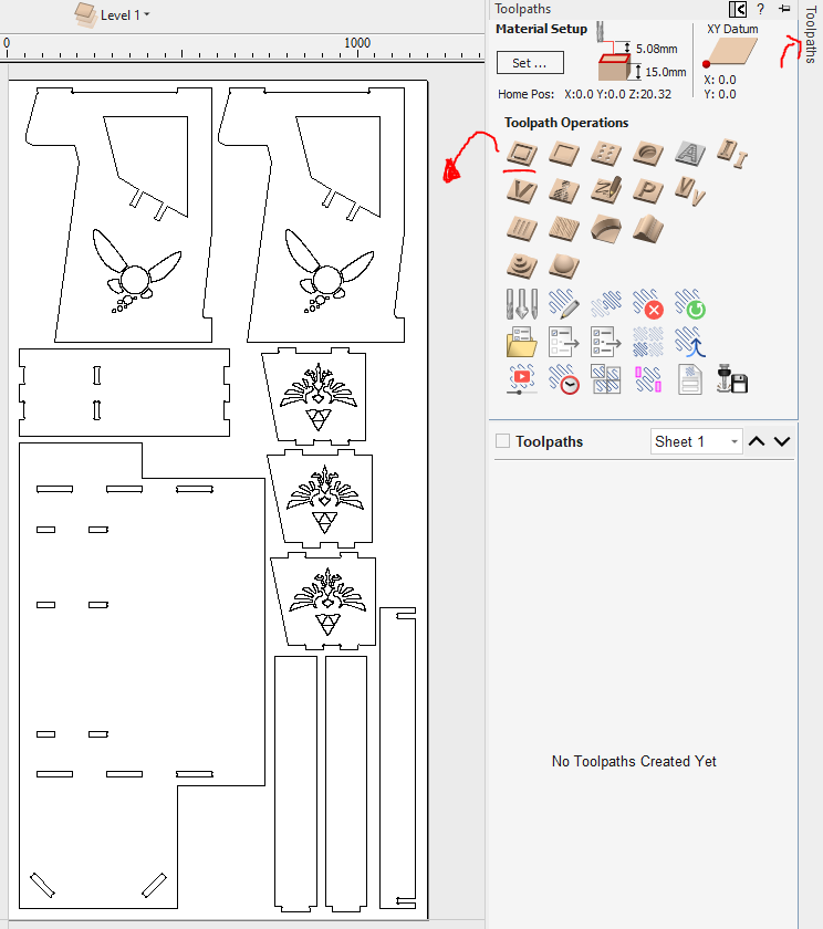
5. Toolpath Definition and machine vectors
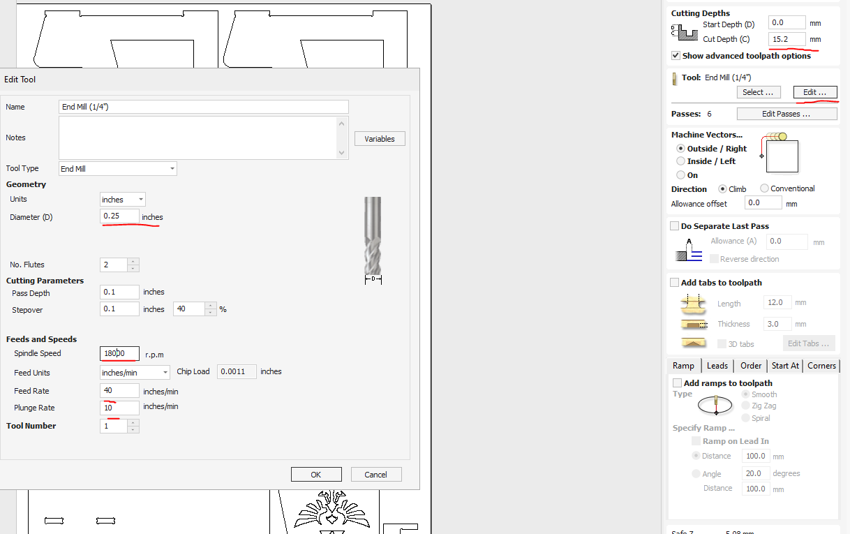
For machining, I choose a 1/4” two-flute carbide end mill, ideal for cutting plywood cleanly and efficiently. I define the profile toolpaths, setting a cutting depth slightly deeper than the plywood thickness (15.2mm) to ensure complete separation.
I adhere to the following machining parameters based on previous experience the values established in the group assignment, also I kept everything a bit slower than normal only to be safe:
- Spindle Speed: 18,000 RPM
- Feed Rate: 40 in/min
- Plunge Rate: 10 in/min
The machine vectors section determines the position of the toolpath relative to the selected vector, and directly affects how the part will be cut.
There are three main options:
- Outside: I use this when cutting the external profile of a part. The toolpath runs along the outside edge of the vector, ensuring the final piece keeps its intended dimensions. This is especially important for preserving the overall shape and fit of outer parts.
- Inside: This is selected when I need to cut holes, slots, or internal features. The toolpath follows the inside edge of the vector, which allows the interior dimensions to remain accurate and avoids material overcutting.
- On the vector: I apply this when engraving lines, creating shallow cuts, or marking features rather than cutting them out. The tool follows the exact center of the vector line, which is ideal when the line itself is the feature I want to machine.
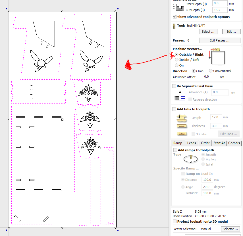
Figure 22: Select the vectors to be cutted by outside.
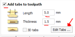
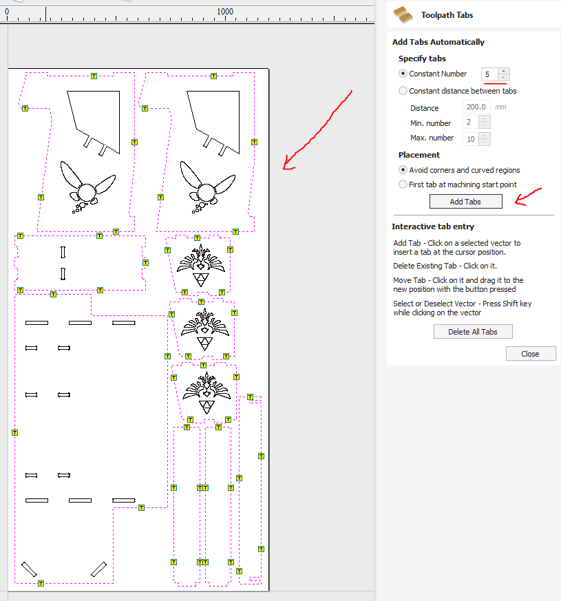
6. Tabs and Holding Strategy
To keep the pieces stable during machining, I strategically place tabs around each component. These tabs are 5mm wide and 1.5 mm thick, ensuring parts remain secure but easy enough to remove afterward.
7. Toolpath Simulation and Export
Before finalizing, I run a simulation in VCarve to check for potential issues or collisions. After confirming that everything looks correct, I export the toolpaths as G-code files compatible with the CNC machine’s control system (postprocessor).
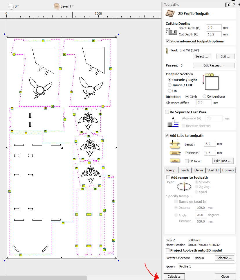
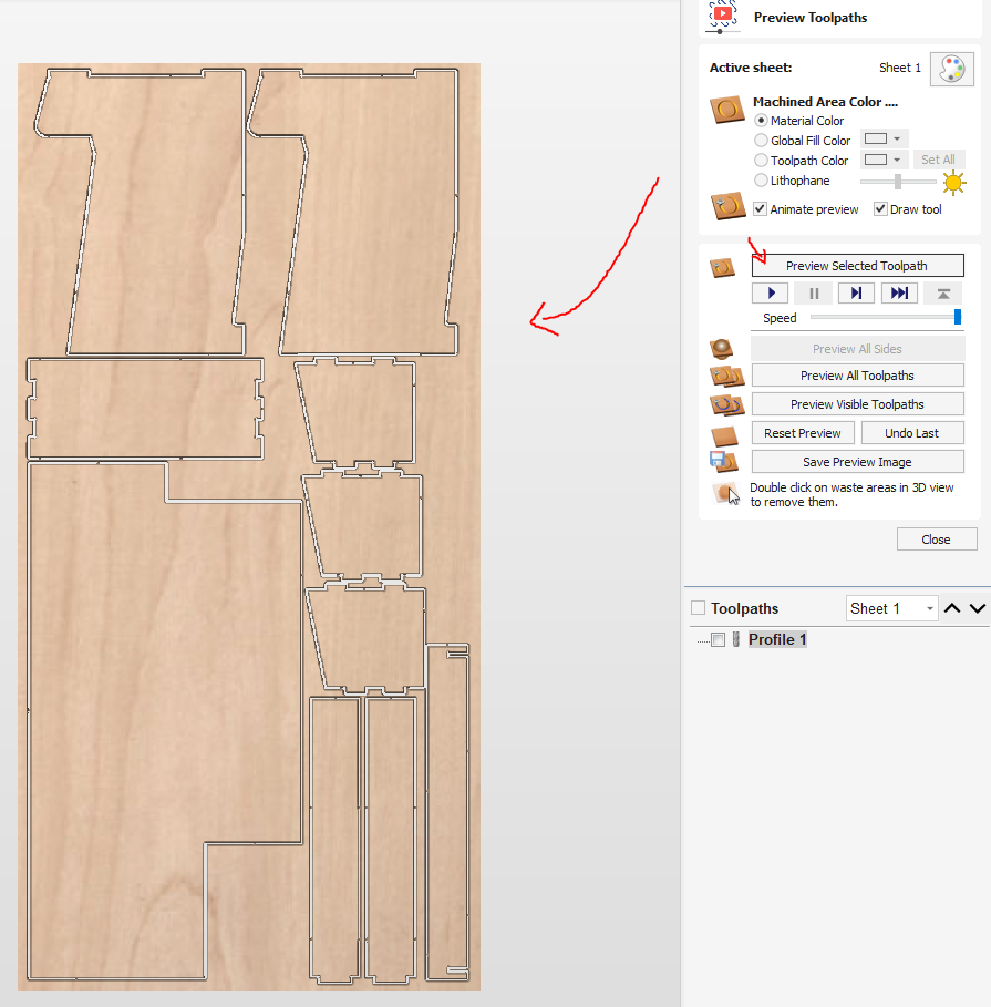
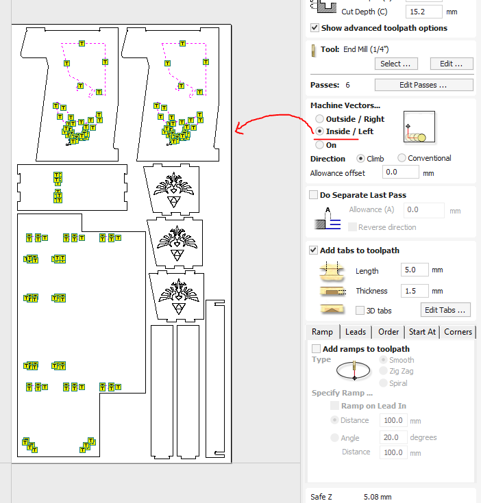
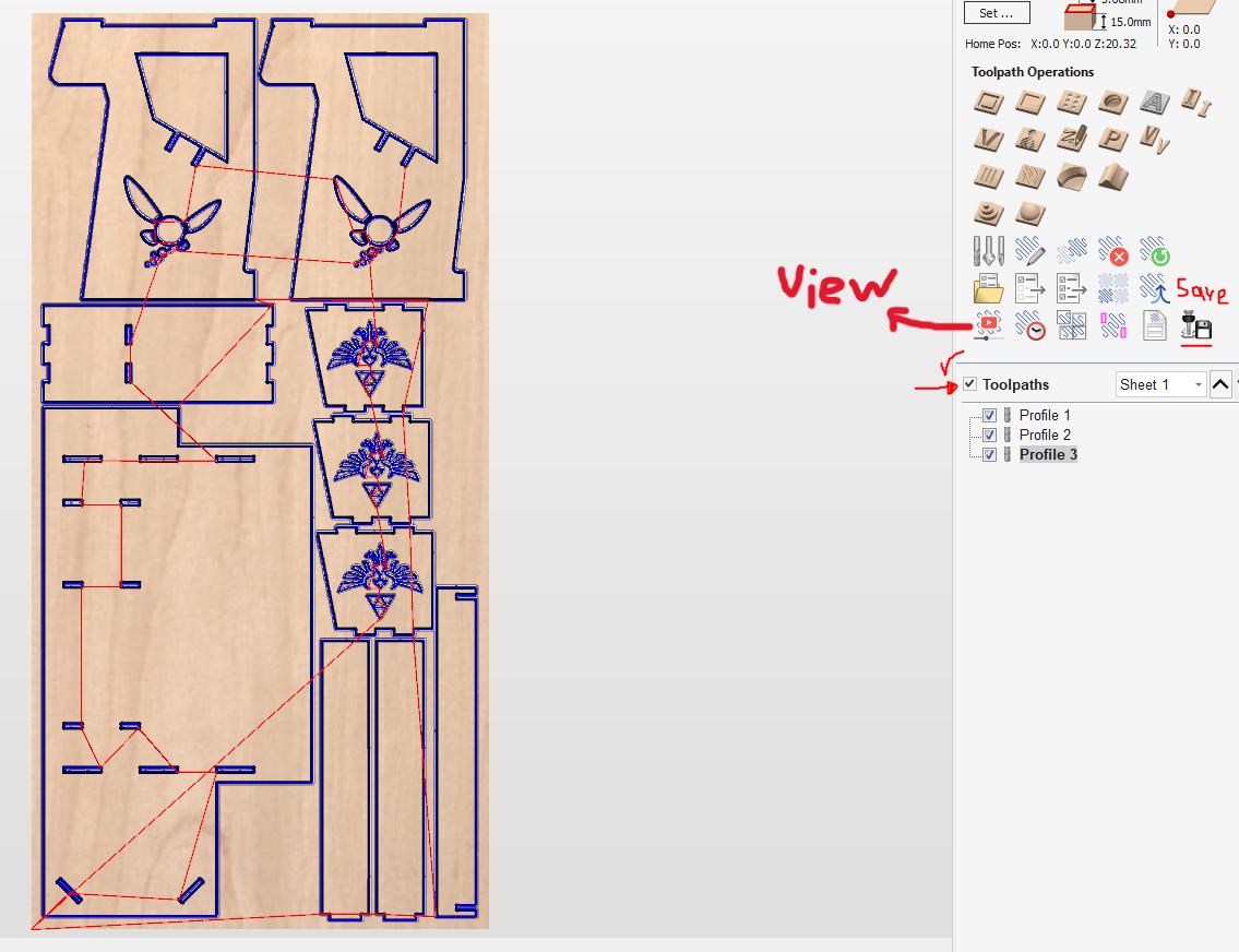
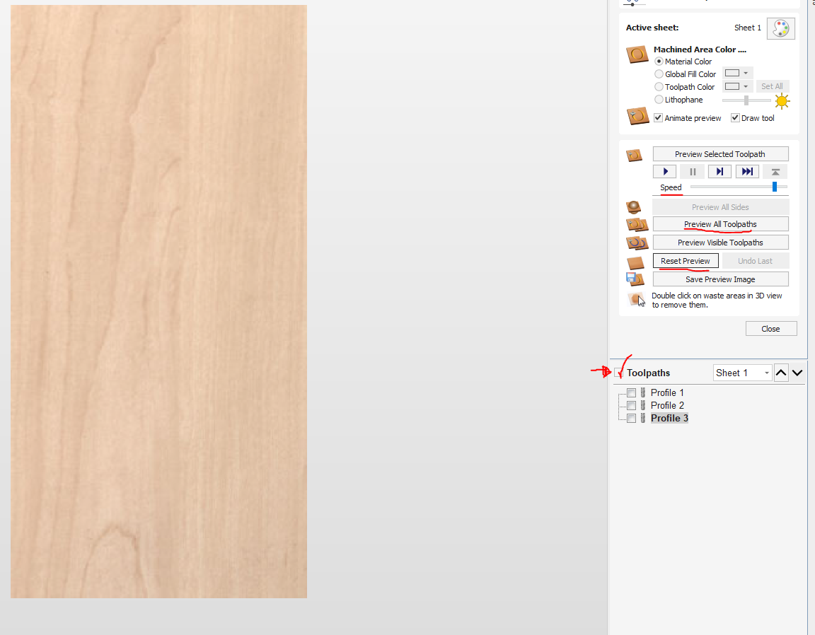
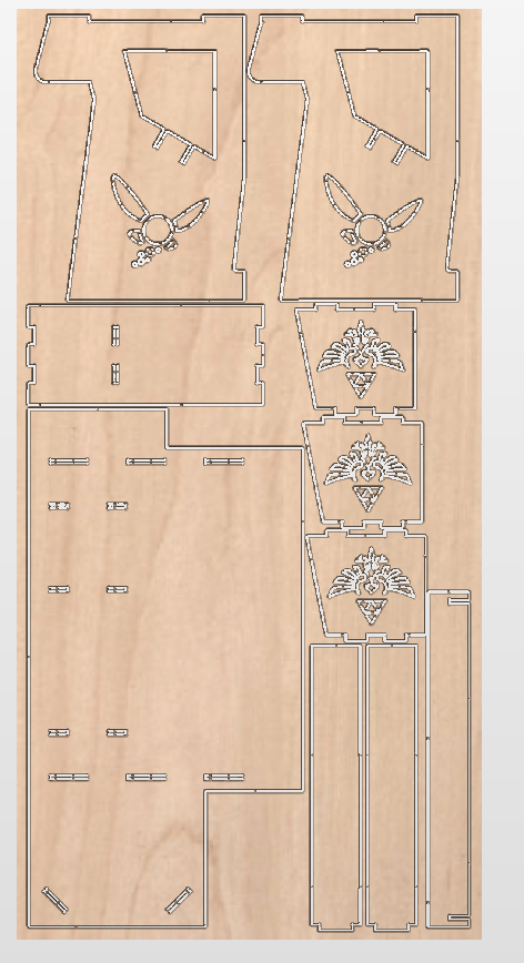
Figure 31: Simulation result.
CNC Machining with Asia Robótica Shop-1325 Router
Now, the physical fabrication process using the CNC router begins. Here’s what needs to be done:
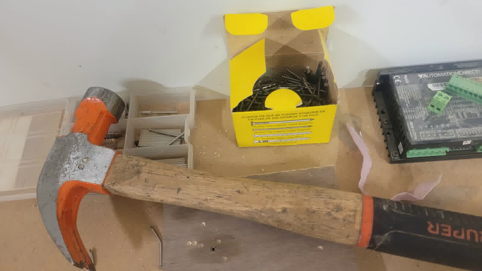
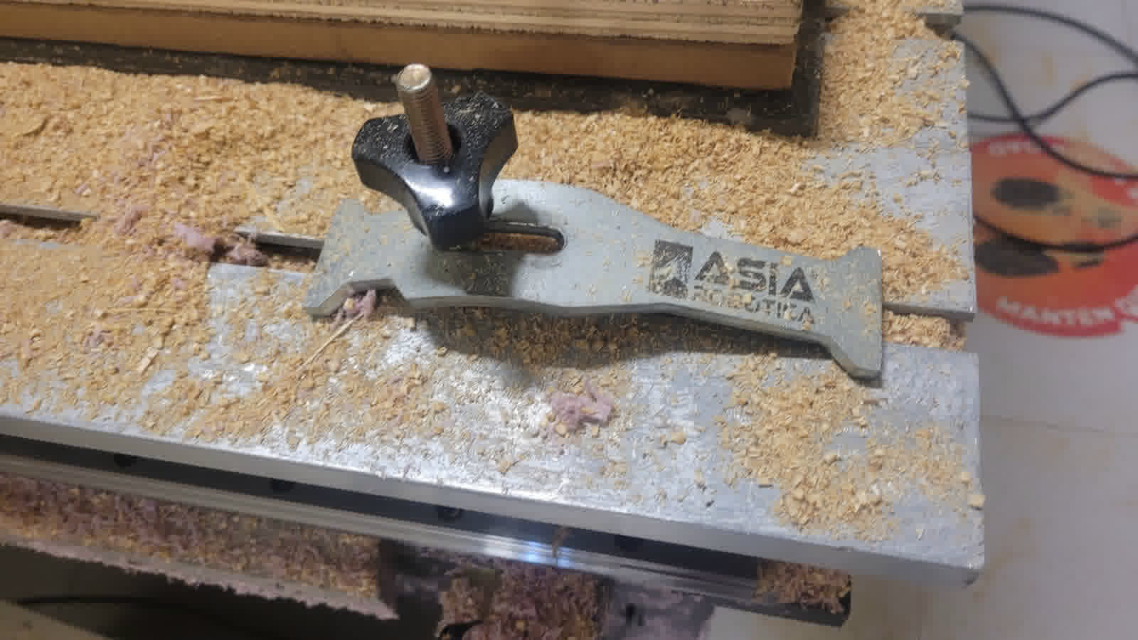
1. Material and Machine Setup
I placed and secured the sheet onto the CNC machine bed, ensuring it was flat and will not shift during cutting. I used both nails and pins to secure the board, since the design was very close to the edge of the material and there was a risk of the end mill hitting one of the pins. The nails helped keep the board in place without interfering with the toolpath.
I inspect the Asia Robótica Shop-1325 router and and changed the cutting tool to the 1/4” end mil considered in Vcarve.
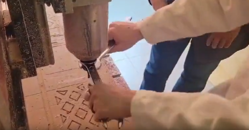
Figure 34: Tool changing.
Once powered on, the router initiates a return to its factory default settings. It is essential to allow this process to finish completely, as it ensures the router can properly reset all zero positions.
2. Tool and Machine Calibration
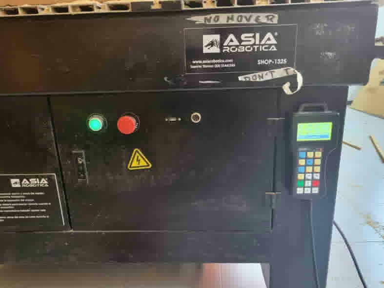
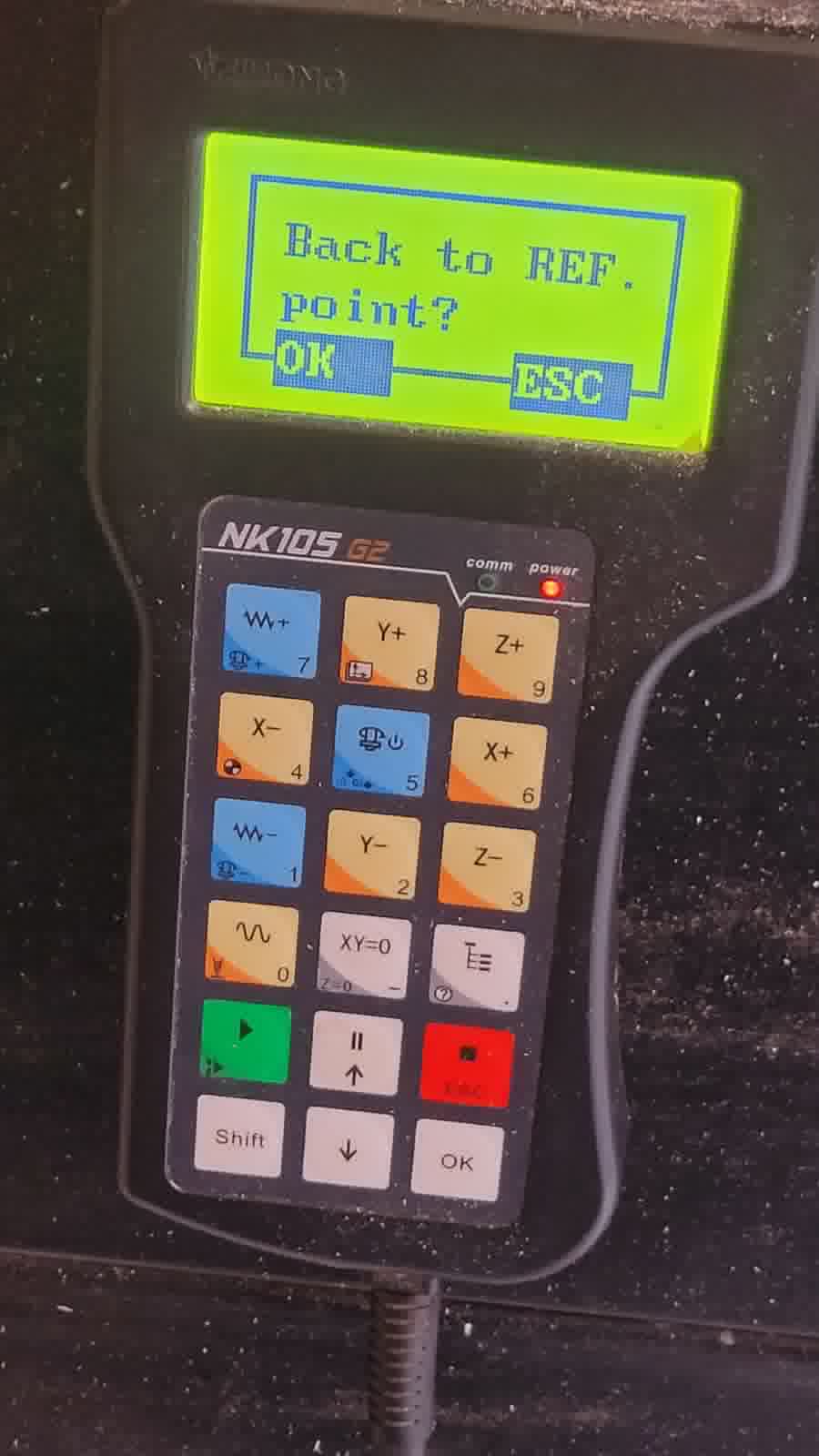
After installing the tool, I accurately zeroed the machine’s X, Y, and Z axes using its built-in zeroing function. To set the origin, I used the XY=0 button (blue square), navigated the CNC using the axis control buttons (purple squares), and accessed the menu through the function buttons (green squares). The red button serves as the emergency stop, ensuring safe operation in case of unexpected behavior.
I take special care in setting the Z-axis zero precisely at the material surface to ensure accurate cuts.
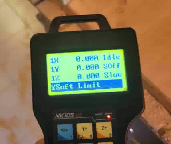
Figure 37: Setting the new origin.
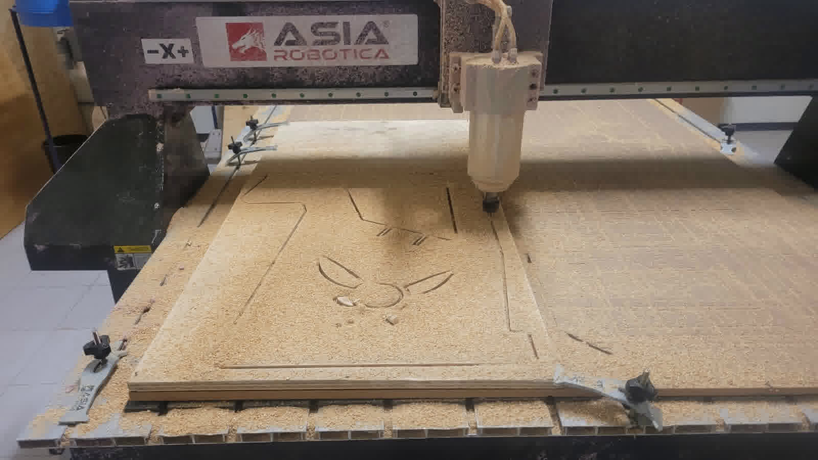
3. Execution of Machining
With everything set, I load the G-code into the CNC controller and start the machining process, closely monitoring the operation. This step requires my attention to promptly respond if any issues arise, ensuring optimal machining performance.
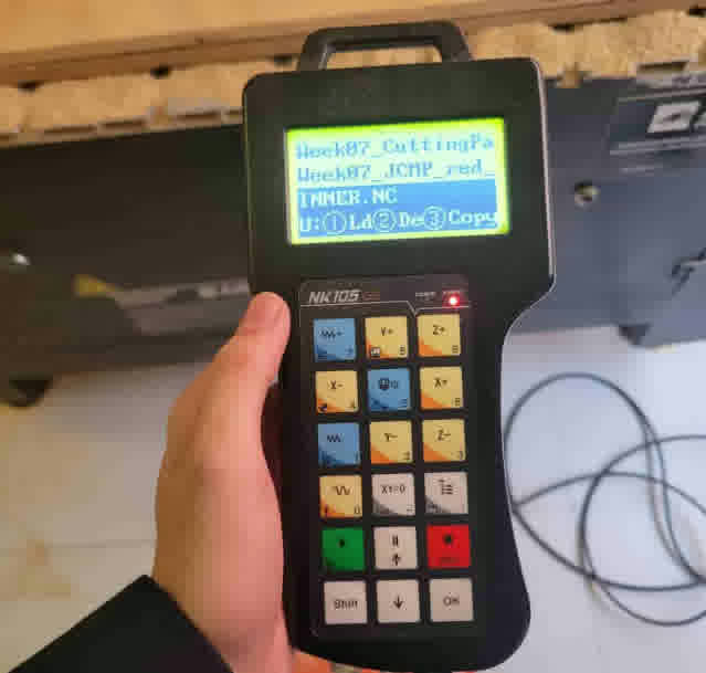
Figure 38: Loading the file.
4. Post-Machining Procedures
After the milling, I safely power down the CNC router and carefully remove both the sheet and individual parts using hand tools, ensuring the integrity of the finished parts.
Post-Processing and Finishing
To enhance the final quality and prepare the parts for assembly, sanding is essential:
- Mechanical Sanding: I use an orbital power sander to quickly smooth out large surfaces, removing any rough edges and tool marks.
- Manual Sanding: For finer details and edges where the power sander can’t reach effectively, I sand manually using fine-grit sandpaper.
This sanding process significantly improves the overall feel and look of the finished parts, making them ready for assembly.
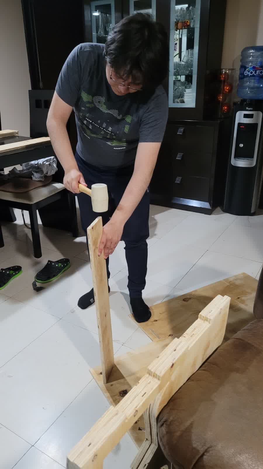
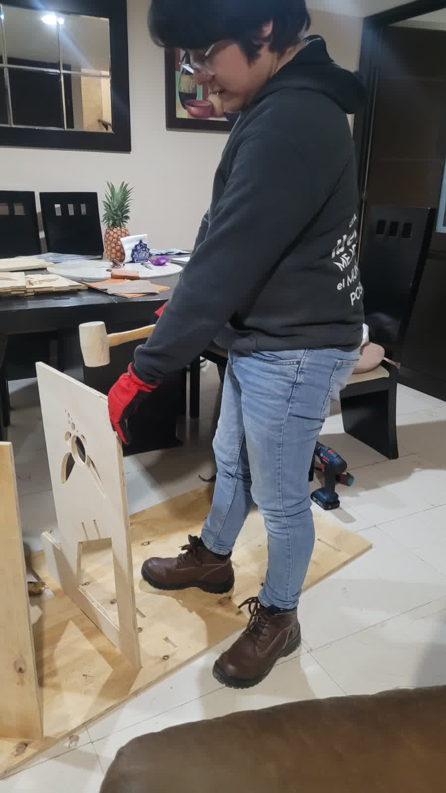
After hours of assembly (special thanks to past-Erwin for choosing zero tolerance—making the process much more challenging), I finally managed to put it all together.
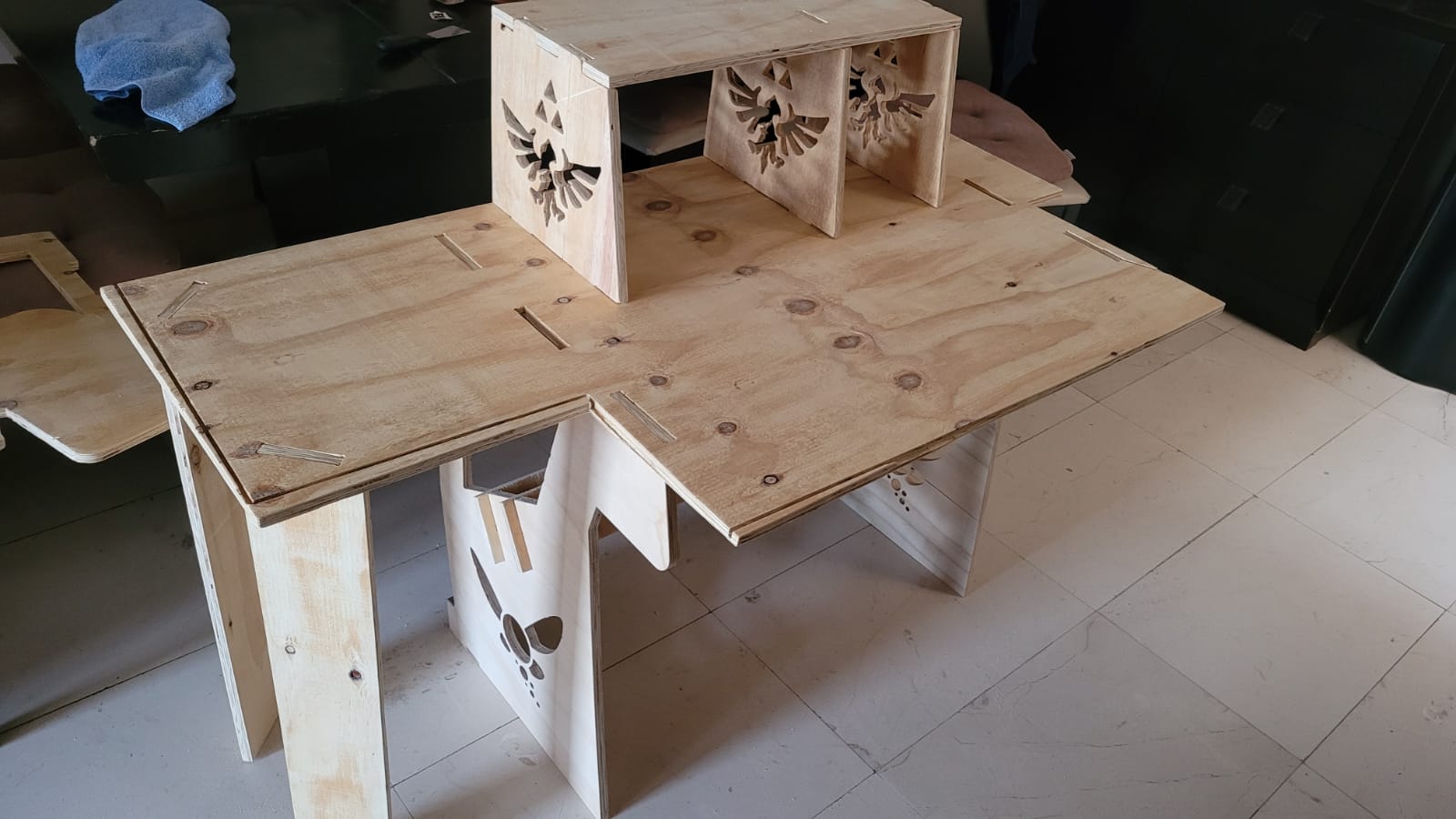
Heroshot
LEARNINGS
As much as I hated the assembly process due to the tight tolerances, I’m also genuinely thankful for having ignored them. Today, this table is incredibly sturdy—I use it constantly, and it doesn’t wobble or shift at all. It's reliable, and I’m proud to use something I built myself. (Thanks, past-Erwin. You're forgiven.)
What’s more, building it taught me to think more carefully about material selection. In the end, I had to recycle leftover plywood from classmates, especially after one piece cracked during a forced assembly. That mistake led me to repeat the milling process for the broken part—an important lesson in both tolerance and patience.