Scanning
This week, I honestly struggled deciding what to scan, because I wanted something visually appealing, difficult to model, and practically useful beyond just a print. After conversations with friends, I decided to scan a hand capable of holding my phone. This way, besides showcasing the print quality (the hand model), it also serves as a stand.
Therefore, I proceeded to do the scanning using Creality Scan software, which you can download from the following link. The Creality Scan application is very user-friendly and intuitive. You simply connect the scanner to your computer and start scanning, in this case, I used "CR-Scan Ferret Pro from Creality 3D".
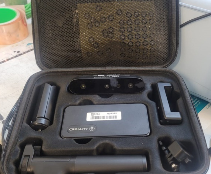
Figure 1: Creality Scan device.
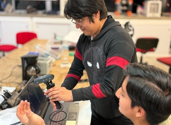
The scanning process requires careful handling since you must move the scanner carefully around the object so it can accurately identify its geometry and/or color. In this case, while the scanner can identify both, it allows you to select which feature to prioritize at the beginning of each project.
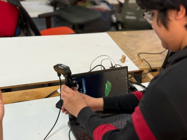
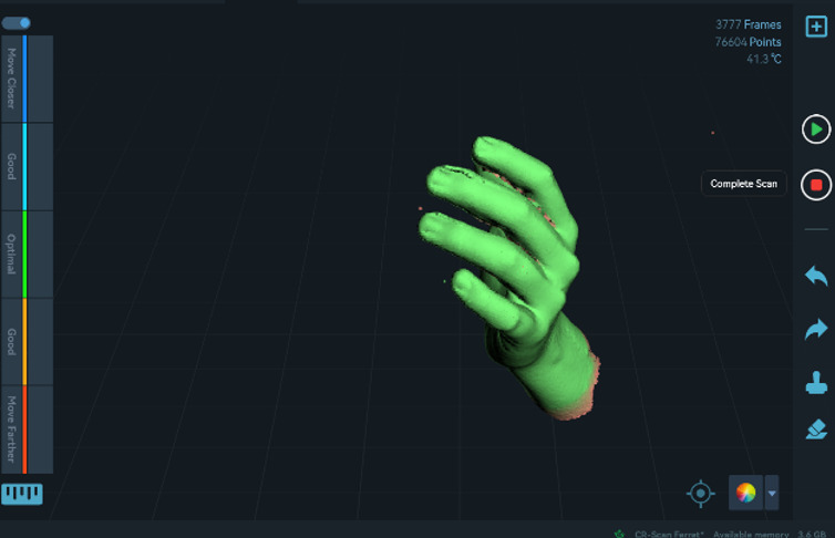
The software itself helps you during scanning by displaying a sidebar to the left of your scan, which shows how well the scanner "understands" the object. Your goal is to maintain the scan within the green "Optimal" area. This feedback helps you understand if you are too close, too far, or incorrectly positioned. Additionally, the software shows real-time feedback of what the scanner is capturing at the center of the interface, providing a comprehensive overview. On the right side, there is a pause button for when you need to make sudden movements or jumps, and another button to finalize the scan.
.jpg)
.jpg)
Figure 6: Detailed view of the scanned hand model (Post-processing result).
The scanned hand model itself could easily be sent directly for printing, with minor adjustments done in slicing software (Ultimaker Cura, PrusaSlicer, OrcaSlicer) based on specific needs. However, as previously mentioned, I wanted this model to serve not only as an aesthetic piece but also as a practical holder for my phone, both horizontally and vertically. Therefore, additional aesthetic adjustments and a suitable base are required. To achieve this, I decided to perform some editing in Blender, as the file was too heavy to open in Tinkercad without quality loss, and other 3D modeling software had limitations regarding my specific needs.
When importing the ".obj" file into Blender, a menu appears where you can slightly edit the object. However, since I didn't want to change anything regarding the scale, I simply clicked "Import".
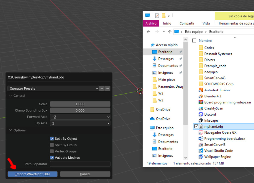
Figure 7: Importing the .obj file into Blender without scale modifications.
To move any object in Blender, select it and press "G" to move it freely. For better control, specify the direction by pressing "G + desired axis". For example, "G + Z" will move the object only along the Z-axis.
However, the model had certain imperfections due to scanning errors or incorrect scanner movements. Therefore, in Blender, I decided to reduce these imperfections using sculpting tools. In this case, I used the "Smooth" brush, which expands the surface to fill holes or smooth rough areas by pushing vertices outward. Pressing "Shift" applies the brush inward, while not pressing "Shift" applies it outward. Use "F" to increase or decrease brush size, and "Shift + F" to adjust brush strength.
Upon closer inspection, I noticed an unnecessary disconnected part. To remove this and similar sections, I proceeded as follows:
- Enter Sculpting mode and select the "Mask" tool.
- Carefully mask only the part you want to remove. The mask tool works similarly to a brush, so you can adjust its size and strength using the same commands as the "Smooth" brush.
- Next, select the "Mask slice to new object" tool from the top menu. This separates the masked section into a new object.
- Finally, after the separation, simply delete the new object by pressing "Delete", completely removing that section.
- However, some disconnected fragments might remain. These fragments can be removed by selecting them directly in Edit mode. Select a node, edge, or face, then press "L" to select all connected geometry (in this case, only the fragment).
- Press "Delete", and when prompted, select vertices to remove the entire fragment. Initially, Blender incorrectly detected points as being connected, causing entire hand selection upon deletion attempts.
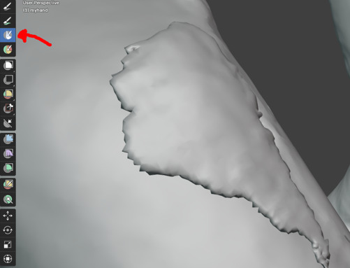
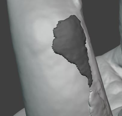
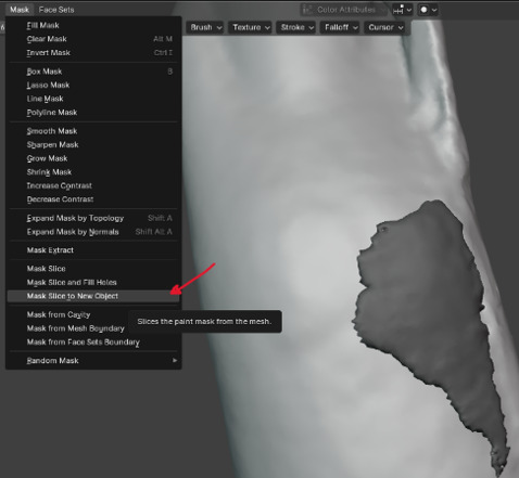
Figure 10: Using "Mask slice to new object".
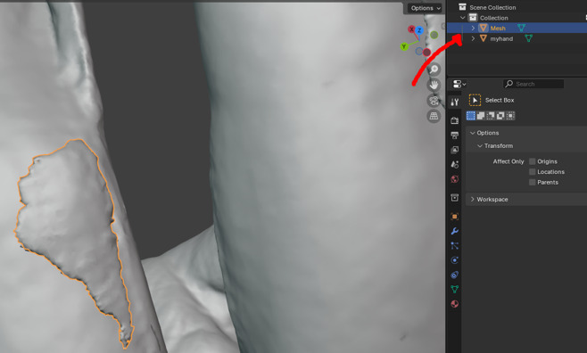
Figure 11: Deleting the separated object.
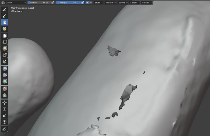
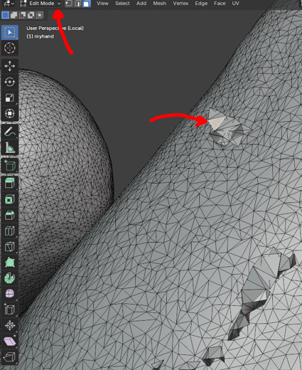
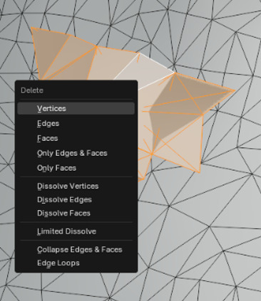
Figure 14: Deleting fragment by selecting vertices.
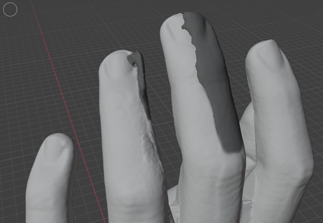
If a fragment is difficult to remove, repeat the process but choose "make slice and fill holes" to create a closed geometry that you can immediately sculpt.
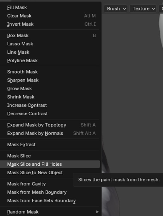
Figure 15: Using "make slice and fill holes".
Although this method is useful for covering large areas, the scanner generates many points, making it not always the best option, as illustrated in the following images:
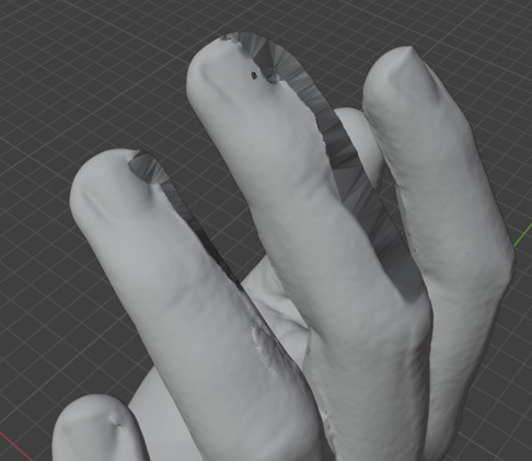
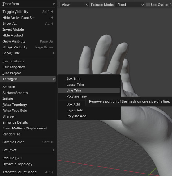
Even though the model might look corrected and ready for further brush applications, it's not that simple. Cutting large parts removes many points, and due to complex geometry, achieving detailed finishes is challenging. Therefore, I recommend frequently alternating between brushes. Personally, I used "Trim" (which works like an eraser flattening surfaces) and "Inflate/Deflate" for small volume adjustments (similar to inflating or deflating a bubble).
However, the most useful brush was "Smooth". Although slower, given the number of points, it provided better details. Thus, after approximately one hour of work, the final result was:
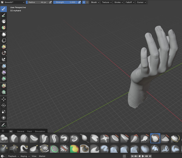
Figure 18: Final sculpting results with improved details.
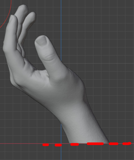
Although changes might not be easily noticeable, I did my best to improve the surfaces the scanner could not accurately capture. Finally, in Blender, I proceeded to create a base for the hand. I started by cutting part of the hand and creating a rectangular prism base below the cut.
Next, I created a cube. But before doing so, I recommend aligning the hand in the center for easier and quicker processing (this step is optional but helpful). To add a cube, in Object mode press "Shift + A", then select "Mesh" and finally "Cube" from the dropdown menu.
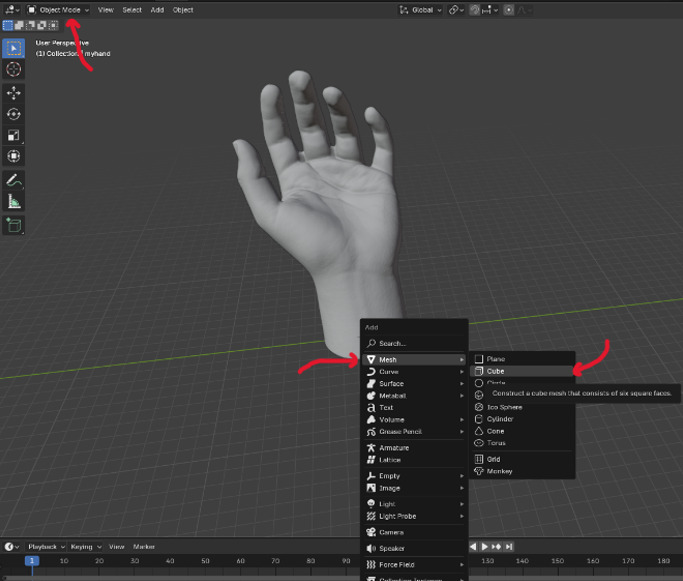
Figure 21: Creating a cube at the center of the project.
In "Edit mode", you can edit the cube by clicking on one of the faces and then pressing "G + axis" to resize in the desired direction. This works similarly to moving objects; however, since we are in "Edit mode", it changes the object's dimensions instead. Make sure you are in the face-editing mode to perform this operation.
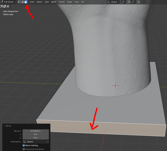
Figure 22: Resizing the base cube in Edit mode.
After creating the base, I unified the pieces by selecting both the hand and the base and pressing "Ctrl + J". As a decorative touch, I wanted the base to display the text "FAB ACADEMY". To do this, I pressed "Shift + A" to open the add menu and selected "Text".
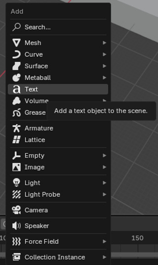
Figure 23: Adding text to the base.
After adding the text, I proceeded to move and rotate it to align it exactly where I wanted. Once positioned, I extruded the text using the following operation:
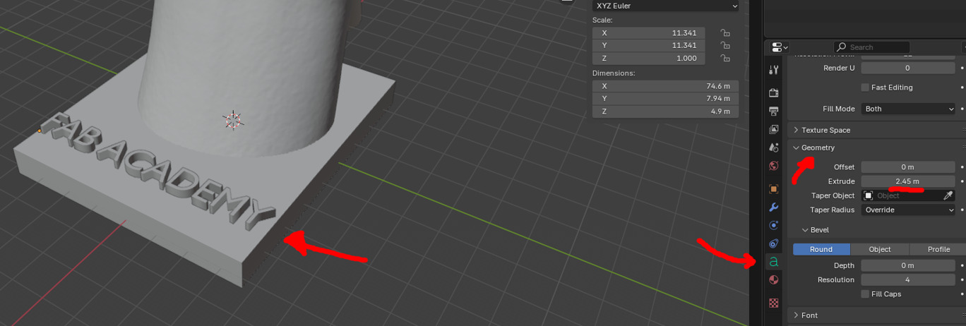
Figure 24: Extruding the text to create depth.
Lastly, I noticed the phone could potentially fall when held, so I decided to implement a cone-shaped support. The procedure to add this support was similar: press "Shift + A", then select "Mesh" and choose the desired object (in this case, a cone). I repositioned and adjusted it using previously mentioned movement commands. For a smooth finish, I switched to "Object mode", left-clicked, and selected "Shade Smooth".
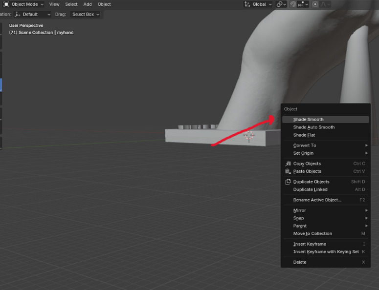
Figure 25: Smooth finish.
Finally, I unified the base with the hand by selecting both and pressing "Ctrl + J". Then, I exported the model in ".stl" format, which I then imported into PrusaSlicer to print on the mk4s printer. Since PrusaSlicer is specifically designed for the mk4s, I did not need to make many adjustments to the slicing settings. Regardless, I recommend reviewing our "group assignment" for detailed parameters involved in our prints.
In this case, since the model already has sufficient adhesion area, no raft is required. The printer nozzle is 0.4 mm, and the material I chose is PLA. Since I aimed for balanced print quality (neither excessively fine nor rough), the default 0.2 mm PrusaSlicer setting worked well for me.
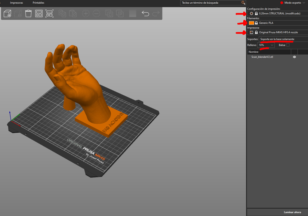
Figure 26: Setup in PrusaSlicer.
Regarding supports, I decided to use them because the model has some overhangs that, although within the 30° limit (they exceed this angle), were concerning to me. To ensure print quality and avoid risks, I chose to use supports only from the base, specifically organic tree supports.
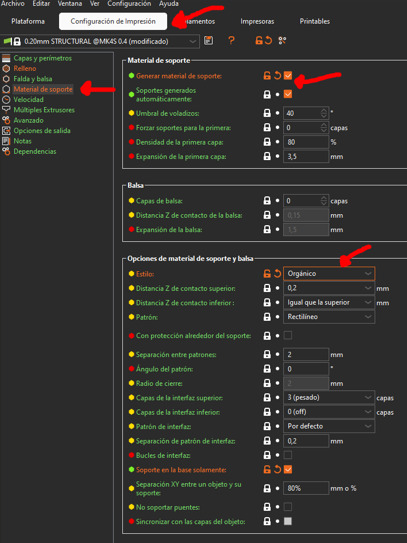
Figure 27: Configuring organic tree supports in PrusaSlicer.
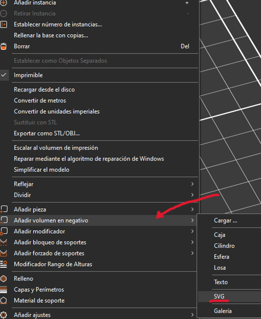
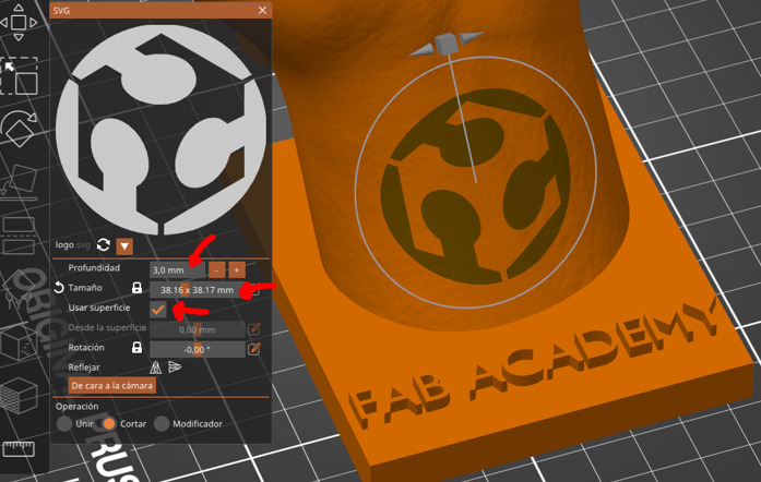
Additionally, PrusaSlicer allows adding text or an SVG file directly to my ".stl" file. Thus, I decided to embed the FAB logo into the center of the wrist area as negative space (engraved inside the wrist).
After slicing the file, I finally exported it as ".gcode" and sent it to print.
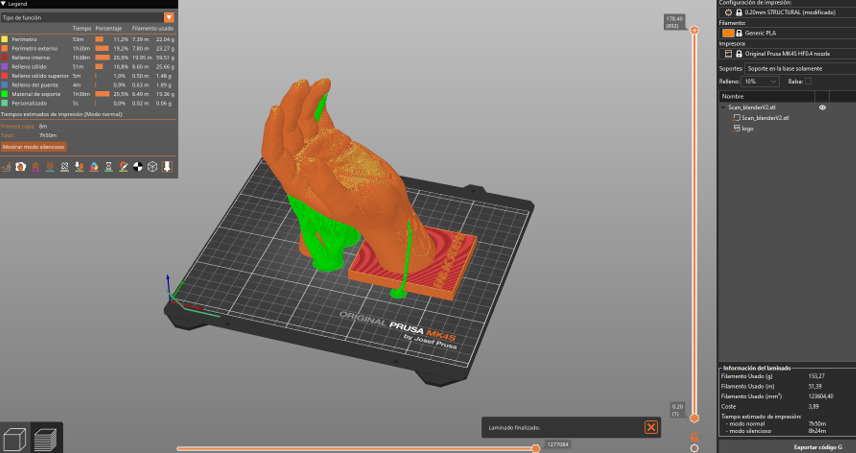
Figure 30: Final sliced model ready for printing.
HERO SHOT! Hand scanned.
3D Printing
Honestly, I had many ideas for this week, but I didn't want to overexert myself since I have my pending project. Therefore, I decided on something simple yet experimental. Recently, I've noticed online attempts at simulating springs with 3D printing. Although not entirely new, it caught my attention through algorithm-based YouTube recommendations. These videos inspired me to create a bobblehead-like figure that could move its head similarly to those seen in movies or placed in cars.
My concept involved creating a spring or elastic platform allowing the head to tilt sufficiently to the sides and then return to its original position (like a typical spring). Here are my initial ideas:
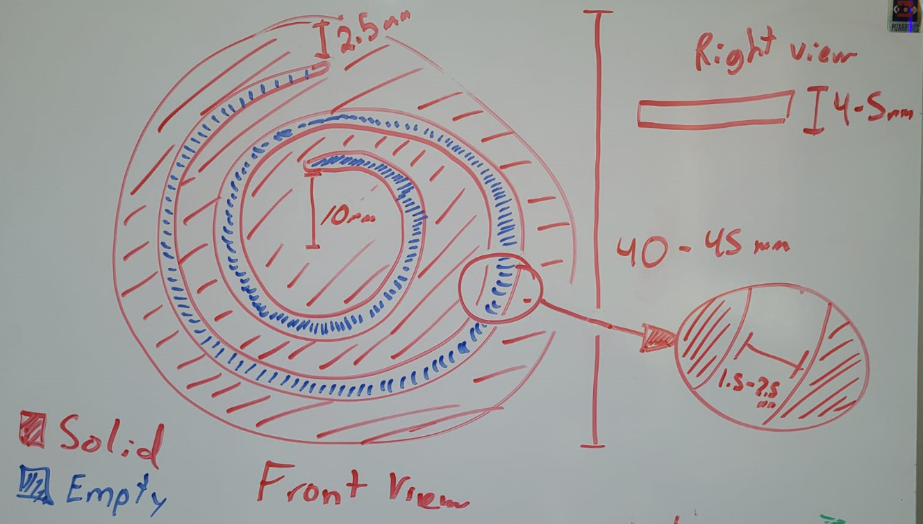
Figure 31: Initial concept sketch for the spring design.
Initially, I planned to create multiple designs of this spring and see which worked best. For now, I would only focus on this component, printing multiple versions until finding the ideal one.
When designing the spring in Fusion 360, I initially struggled to properly trace the spiral. I briefly considered something like a Fibonacci spiral by possibly adding an equation, but this seemed excessive for something simple. Eventually, I realized the best approach was to literally create a 3D spring and then project it onto a plane, ensuring I achieved the perfect silhouette for my spring design. I did this as follows:
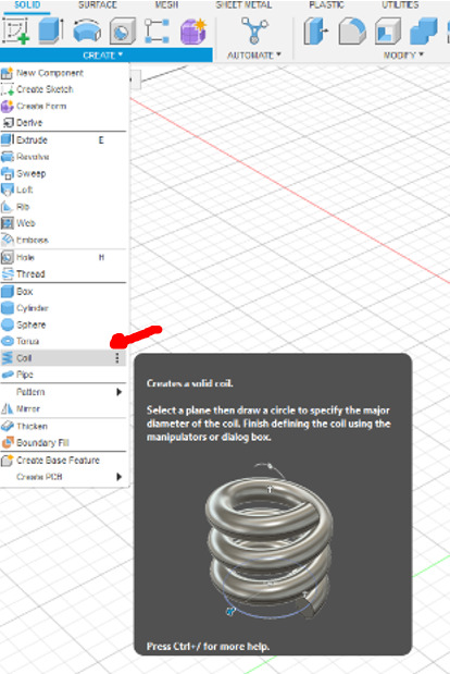
Figure 32: Selecting the coil tool in Fusion 360.
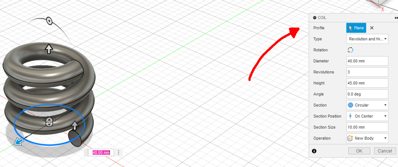
Figure 33: Coil parameters menu.
After creating the coil, adjustments were easily made using the parameters menu on the right. For better visualization, I activated the Top View and varied parameters based on my needs. Critical parameters included diameter, revolutions, angle (negative in this case since I wanted an inward spiral), and "section size". Height was less crucial here, as the objective was to project the spiral. However, extremely high or low values could cause issues in generating the spiral. Additionally, the "section" parameter defined the shape of the coil; to simplify the projection, I chose a square shape.
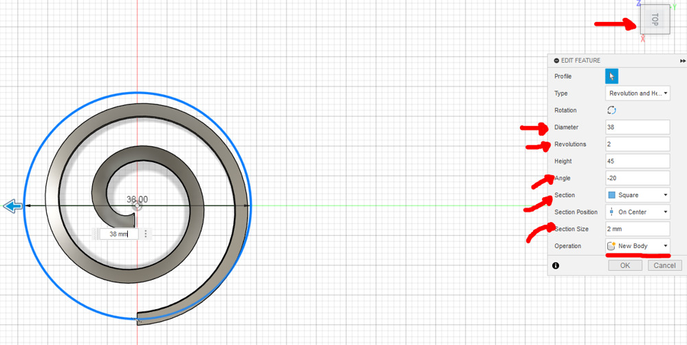
Figure 34: Adjusting coil parameters.
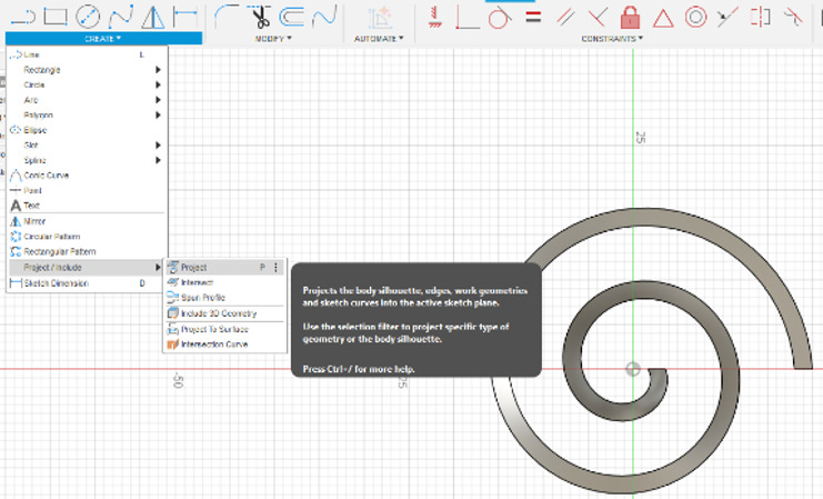
Once this was done, I simply created a sketch on the TOP plane and projected the spiral.
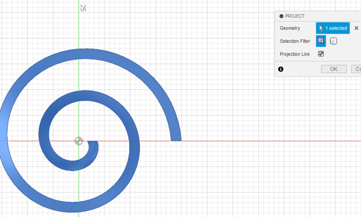
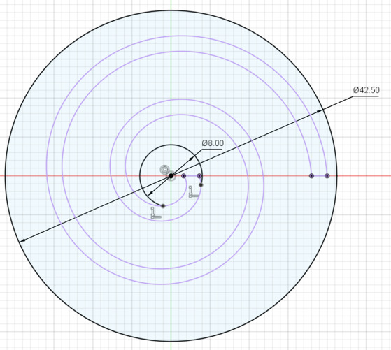
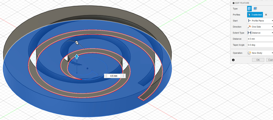
The spring is now created. To finalize the design, I simply drew an outer and inner circle and extruded the sketch.
Finally, to test the spring, I added a pivot at the center to evaluate the flexibility and resistance of the design. I exported the model as an ".stl" file and printed it without supports.
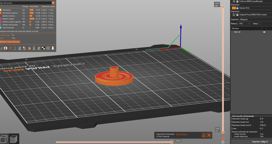
Figure 39: Test print setup in PrusaSlicer.
Indeed, the initial parameters weren't optimal. Therefore, I adjusted the spring parameters several times until I found the best behavior. The final parameters were as follows:
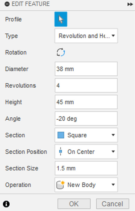
Figure 40: Optimized coil parameters found by testing.
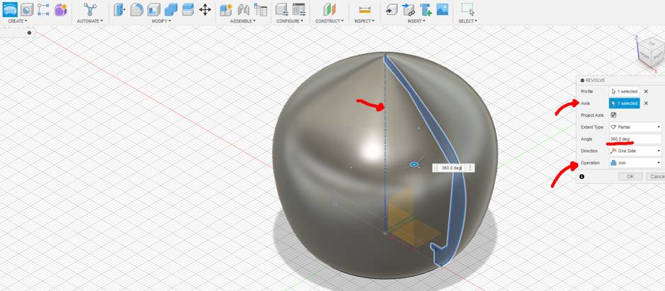
With the suitable spring ready, I proceeded to create the base for the body. First, I removed the pivot and began editing the design to create the head. At this stage, I realized that overhang control was critical; otherwise, my print might fail. Given the head needed to be largely hollow and supported only by the sides of my spring, I made sure most overhangs stayed within a 30° angle limit. Keeping these considerations in mind, I adjusted the sketch to my preferred final shape.
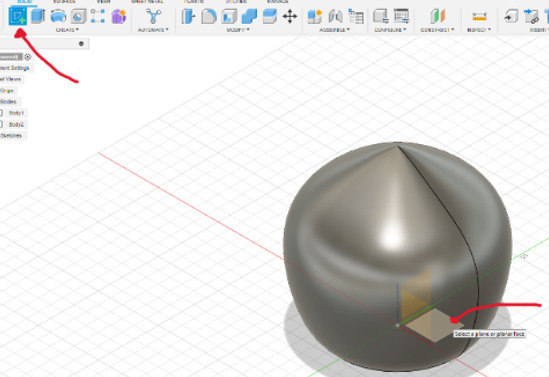
.jpg)
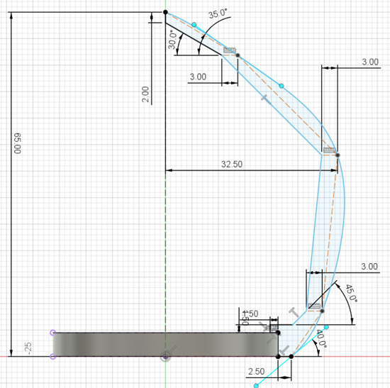
For aesthetic reasons, I decided to conceal the neck. Therefore, I edited the original sketch used for the revolve operation of the head, modifying the dimensions to hide the neck section effectively.
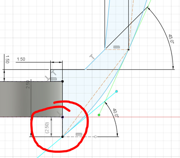
Figure 45: Adjusting sketch to hide neck area.
.jpg)
.jpg)
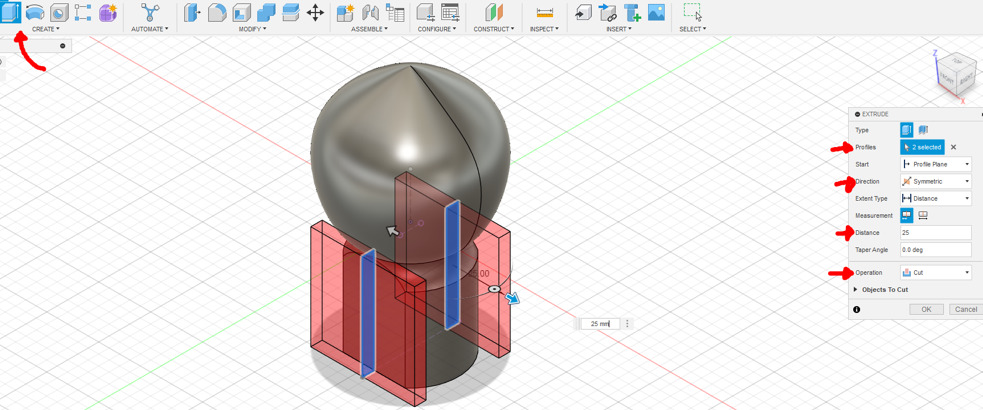
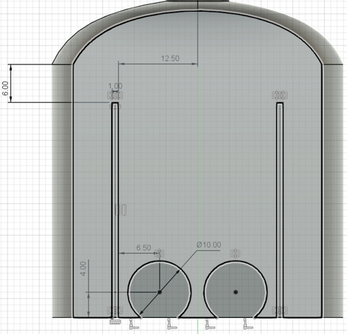
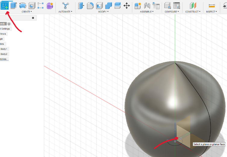
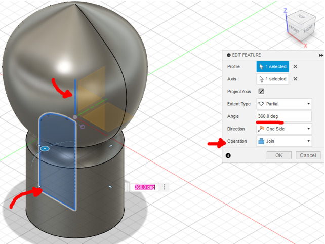
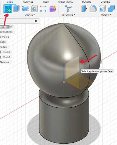
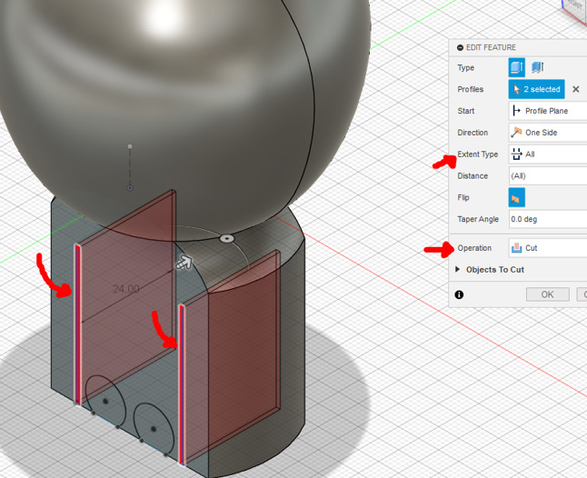
Figure 52: Select the front plane of the body and skecth from there shapes for extruding and cutting.
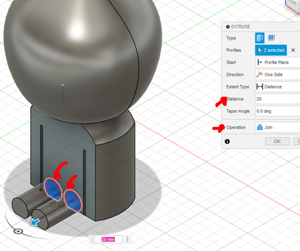
.jpg)
.jpg)
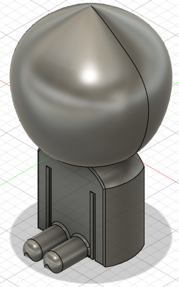
This was how my bobblehead turned out. Initially, I considered editing it further in Blender, but after several attempts, I decided against it as the results weren't convincing, and the process was troublesome. Therefore, I decided to move forward with this current design, naming it "Dummy". Finally, I exported it as an ".stl" file for printing.
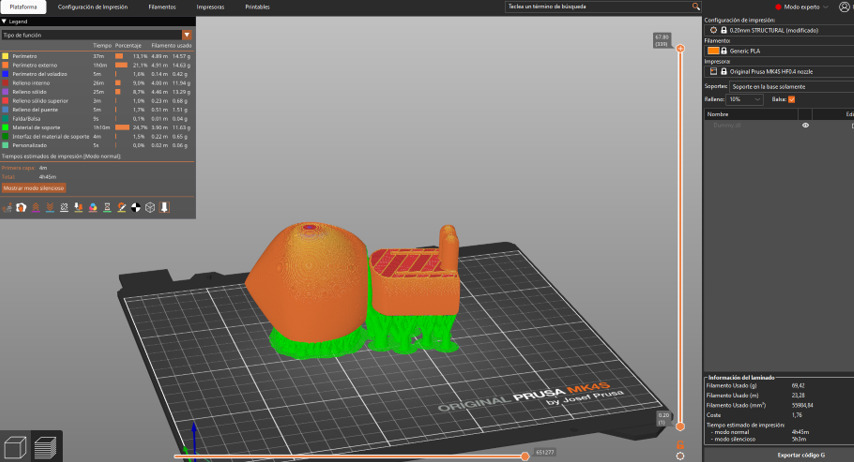
I positioned my model at the previously shown angle because the printer encountered difficulties generating supports for the neck spring overhangs. By orienting the spring in a more vertical alignment, I minimized the required support material, optimizing both its distribution and effectiveness in that region.
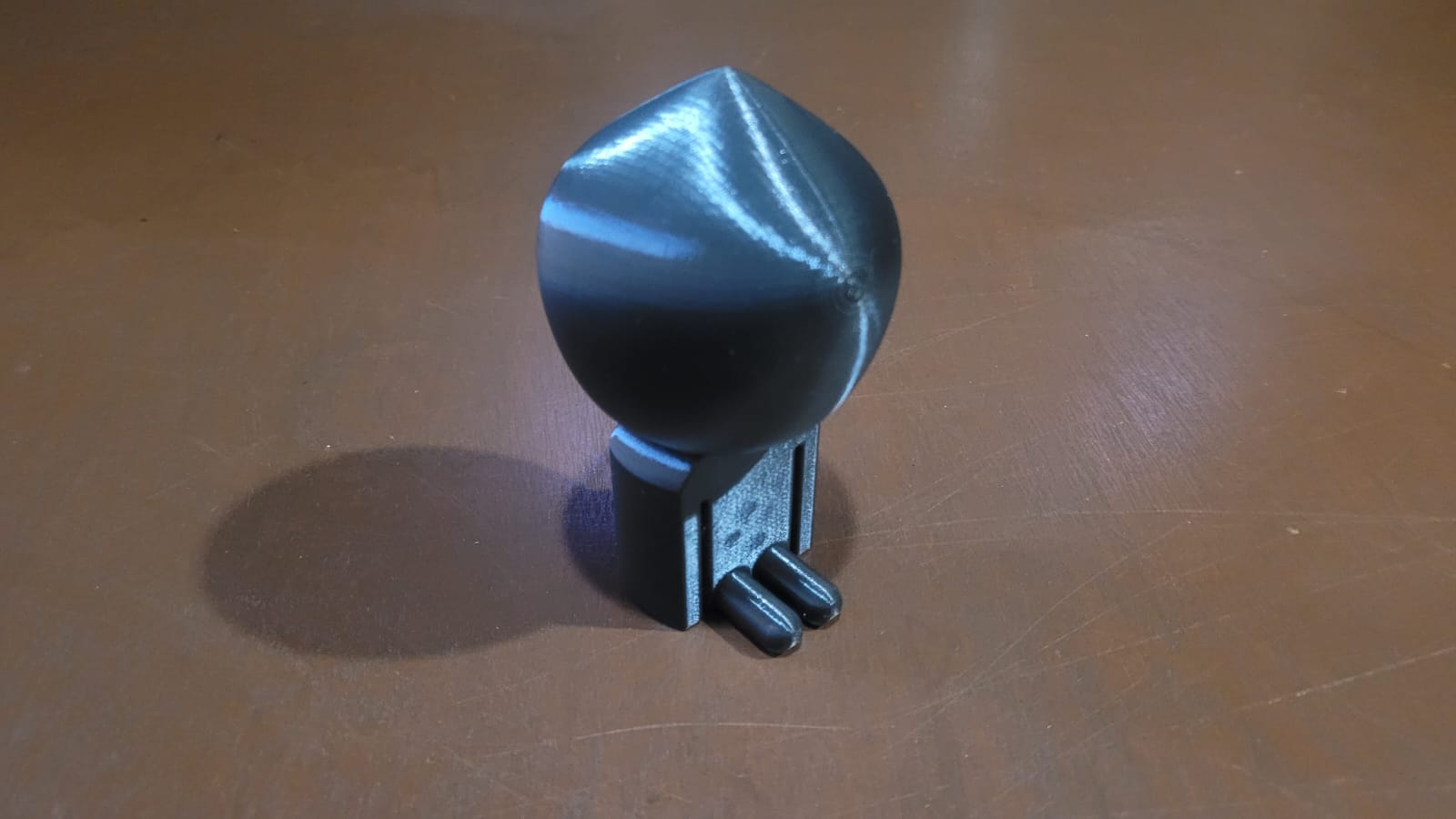
HERO SHOT! Bobblehead.
Why a bobblehead is not easily made by substractive methods?
The shape of the body makes it difficult to manufacture using traditional subtractive methods. However, the biggest challenge is the spring inside the neck. Apart from its curved and complex shape, the fact that it is hidden and only connected to the inner walls of the head makes it nearly impossible to create using only material removal.
A possible solution would be to manufacture three separate pieces (the body, neck, and head) and then assemble them. However, this approach highlights a major limitation of subtractive manufacturing. While it allows for complex shapes by cutting and assembling parts, it does not provide the same flexibility as additive manufacturing. This is why 3D printing is the best choice for this design, as it allows for the creation of fully enclosed structures that would be very difficult to produce with other methods.
LEARNINGS
In summary, this week, although I already knew basic parameters for 3D printing such as inner and outer walls, infill, volumetric speed, overhangs, tolerances, and supports, I realized through the process of printing my bobblehead model that practical application isn't always straightforward. Initially, I faced several print failures caused by improper support generation. Automatic organic or tree supports provided by PrusaSlicer didn't work effectively. Even after manually painting and controlling the support generation within PrusaSlicer, the results were still unsatisfactory. By reorienting the model—compromising slightly on mechanical resistance and increasing the printing time—I achieved better support generation and significantly improved print results.
Additionally, I learned the value of making modifications directly in slicing software rather than relying exclusively on CAD tools, exemplified by embedding an SVG in my hand-scan model. Despite not successfully applying Blender to my bobblehead model, the experimentation deepened my understanding of sculpting tools, mesh behavior in Blender and general 3D modeling, and different perspectives.