Embedded Programming
Embedded programming refers to the development of software that runs on dedicated hardware systems, often with real-time constraints. Unlike general-purpose computers, embedded systems are designed to perform specific tasks efficiently and reliably. These systems are widely used in electronics, automation, medical devices, and IoT, with the MCU (Microcontroller Unit) as their core.
Microcontroller Unit (MCU)
An MCU is a compact chip designed to handle control tasks independently, integrating memory, processing, and peripherals into a single unit. This makes it efficient for low-power and real-time applications without relying on external components.
MCU Architecture
The architecture of a microcontroller defines its capabilities and determines its suitable applications. While not overly complex, its design consists of several key components:
- CPU (Central Processing Unit): Coordinates communication between components and executes program instructions.
- Program Memory: Stores firmware and retains data even when powered off.
- ROM: Permanently stores firmware.
- EEPROM: Reprogrammable ROM that allows electrical erasure.
- Flash Memory: A type of EEPROM that allows data erasure in blocks.
- Data Memory: Stores temporary data and computational results.
- RAM: Volatile memory for variables and stack data.
- Registers: High-speed storage inside the CPU.
- I/O (Input/Output) Ports: Interfaces with external devices via GPIO pins.
- Digital I/O: Reads or outputs HIGH/LOW signals.
- Analog I/O: Converts analog signals to digital and vice versa.
- Peripherals: Includes timers, counters, interrupts, and communication interfaces (UART, SPI, I2C).
Regarding this week, despite having experience with multiple microcontrollers across different architectures (AVR, ARM, RISC, and Xtensa), I chose to focus on a single one that acts as a balanced option for diverse applications: the ESP32 WROOM. Below are comparative graphs of several microcontrollers I tested at FabLab Puebla, supporting my reasoning for this selection.
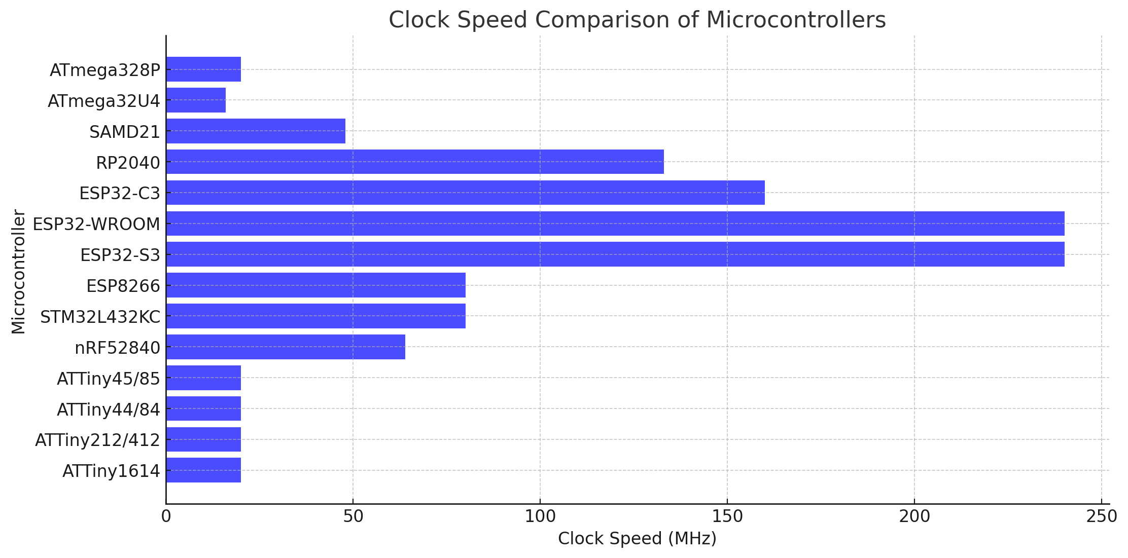
Figure 1: Clock Speed Comparison.
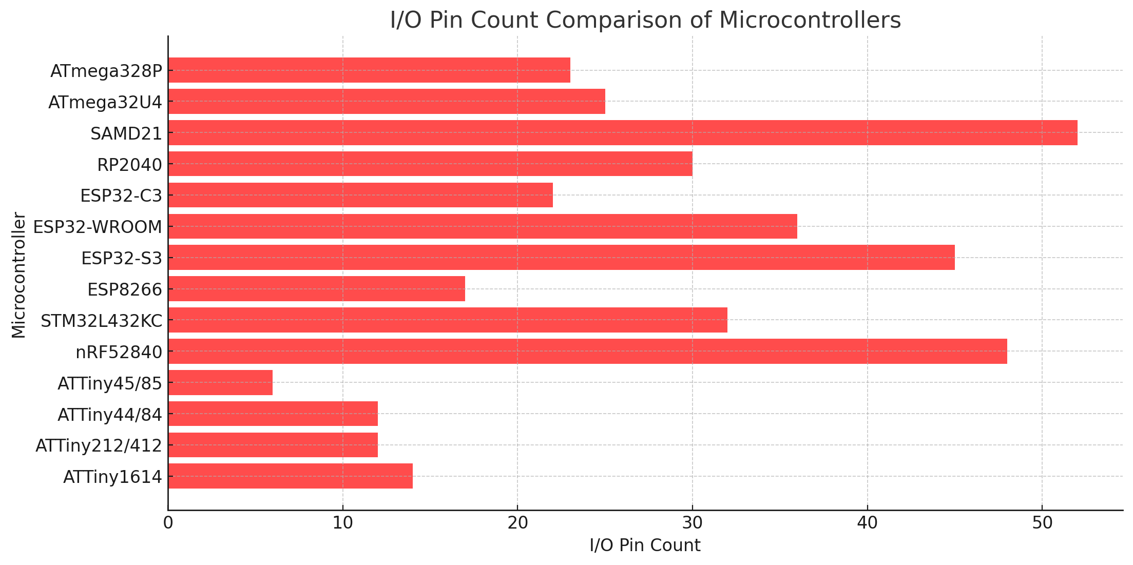
Figure 2: IO Pin Count Comparison.
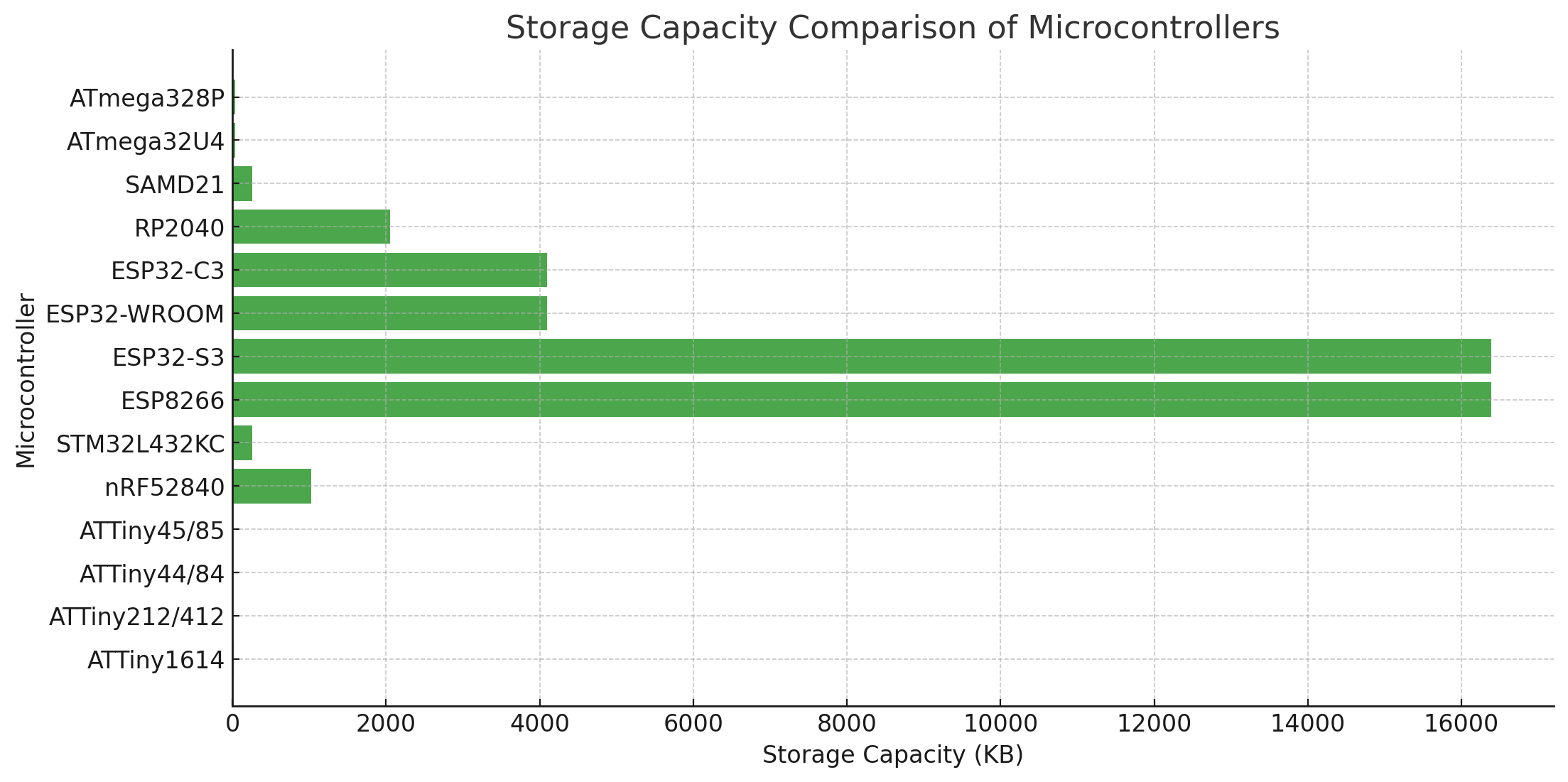
Figure 3: Storage Capacity Comparison.
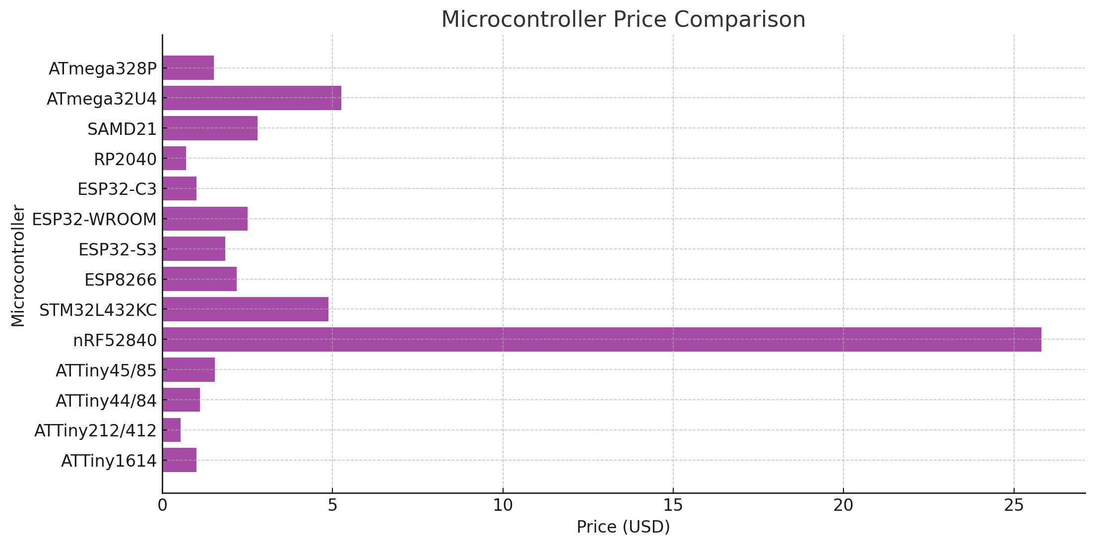
Figure 4: Microcontroller Price Comparison.
For more information, here is the group assignment. Focusing back on the ESP32 WROOM, the table below presents the key data I gathered from the datasheet for Espressif.
| Features | ESP32-WROOM |
|---|---|
| CPU | Tensilica Xtensa LX6 dual-core processor |
| Clock Speed | Up to 240 MHz |
| Bit Depth | 32-bit |
| Storage | Up to 4MB Flash memory, 520KB SRAM |
| I/O Pins | Up to 36 GPIO pins |
| Power | 2.2V - 3.6V |
| Dimensions | 18mm x 25.5mm x 3.1mm |
| Bluetooth | Yes (Bluetooth 4.2 BR/EDR and BLE standards) |
| WiFi | Yes (802.11 b/g/n) |
| How to Program | Serial/UART programming, OTA (Over-The-Air), test pins |
| Special Functions | Wi-Fi Direct, soft-AP, SDIO/SPI/UART interfaces, integrated sensors |
| Temperature Range | -40°C to +85°C |
| Timers | 2 of 64-bit |
| DAC (Digital to Analog Converter) | 2 × 8-bit DACs |
| External Interrupts | Supported on all GPIOs |
| ADC | 2 × 12-bit SAR ADCs with up to 18 channels |
| Price in DigiKey | $2.5 |
| Datasheet | ESP32-WROOM |
To simplify programming, the following image illustrates the pin layout and its features.
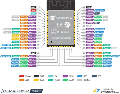
Figure 5: ESP32 WROOM Pin layout.
Regarding programming, this microcontroller offers versatility, supporting both C++ and Python (MicroPython or CircuitPython), two of the most widely used languages for microcontrollers.
Personally, I have experience with C++ and CircuitPython, using the Arduino IDE for C++ and Visual Studio for CircuitPython. For this case, I will prioritize C++ as I am more proficient in it. However, for my final project, I am strongly considering integrating AI, where Python’s simplicity makes it a better choice.
Before diving into programming, here is a comparison of both languages:
General comparison
| Language | Best For | Key Strengths | Limitations | Why Choose It? |
|---|---|---|---|---|
| Python | AI, automation, rapid development, and prototyping |
- Simple and easy-to-read syntax - Large standard library with built-in functions - Ideal for AI, data science, and scripting tasks - Huge community support |
- Slower execution speed than C++ - Higher memory usage - Less direct control over hardware |
Choose Python if: - You prioritize ease of development and readability - You are working on AI, automation, or rapid prototyping - You want to minimize debugging time |
| C++ | High-performance applications, embedded systems, and real-time control |
- More efficient and faster execution - Greater control over system resources - Supports object-oriented programming (OOP) - Flexible memory management |
- More complex syntax than Python - Harder to debug due to manual memory management - Longer development time |
Choose C++ if: - You need high performance and low-level hardware access - You are developing for embedded systems or real-time applications - You want full control over memory and system resources |
Typing comparison
| Feature | Python | C++ |
|---|---|---|
| Declaration | x = 10 | int x = 10; |
| Typed | Dynamic, type is not specified | Static, type must be specified |
| Type Change | Possible at any time | Not allowed, requires explicit conversion |
| Initialization | Optional | Requires explicit type |
| Using Pointers | Does not directly support | Supports pointers (e.g., int *ptr = &x;) |
| Type Conversion | Implicit and explicit | Explicit, e.g., (int)x |
| Integer | num = 5 | int number = 5; |
| Float | pi = 3.14 | float pi = 3.14; |
| String | name = "Hello" | Not directly supported, requires a library |
| Functionality | Python | C++ |
|---|---|---|
| Pin Initialization | led = Pin(2, Pin.OUT) | pinMode(2, OUTPUT); |
| Reading a Pin | button.value() | digitalRead(0); |
| Writing to a Pin | led.value(1) | digitalWrite(2, HIGH); |
| Analog Read (ADC) | pot.read() | analogRead(34); |
| Timers | time.time() | millis(); |
| Printing | print(f"Hello, {name}") | Serial.println("Hello, world!"); |
| PWM (Pulse Width Modulation) | PWM(Pin(2), freq=5000, duty=512) | ledcSetup(0, 5000, 8); |
| Interrupts | button.irq(handler=button_pressed) | attachInterrupt(0, buttonPressed, FALLING); |
| I2C Communication | i2c.scan() | Wire.beginTransmission(0x68); |
| UART Communication | uart.write("Hello") | Serial.println("Hello"); |
Programming ESP32-WROOM
As mentioned earlier, I will focus on C++ and use the Arduino IDE for simplicity. I highly recommend visiting the group page, which provides the necessary links to install the ESP32 family preferences, including the ESP32 WROOM. Additionally, it includes a step-by-step configuration guide for this board.
For my project, I will begin developing an initial control system for the animatronics head. The final version will require AI-driven control. The head's movement involves eight servomotors to control the eyes, beak, and neck. Since integrating AI at this stage would be excessive and difficult to simulate, I will use a simpler method.
Six servomotors will be controlled using potentiometers connected to 3.3V, sending signals to different ADC channels. The remaining two servomotors, responsible for eyelid movement, will be controlled via a timer that periodically moves them between 0° and 90°. To simulate expressions, I will also integrate a button as an interrupt trigger, allowing a predefined gesture to be activated under specific conditions. All of this will be simulated using Wokwi.
    // Include library
    #include <ESP32Servo.h>

    // Define pin assignments
    #define BUTTON_INTERRUPT_PIN 2  // Button to trigger preset position
    #define SERVO_COUNT 8           // Total number of servos
    #define TIMER_INTERVAL 2000     // Timer interval for eyelid servos

    // Servo pins
    const int servoPins[SERVO_COUNT] = {18, 19, 21, 22, 23, 25, 26, 27};

    // Potentiometer pins for 6 servos
    const int potPins[6] = {32, 33, 34, 35, 36, 39};

    // Servo objects (library)
    Servo servos[SERVO_COUNT];

    // Timer and state tracking
    unsigned long lastTimerUpdate = 0;
    bool eyelidState = false; // Toggles eyelid servos

    // Interrupt Service Routine (ISR) - Moves servos to preset positions
    void moveToPreset() {
        for (int i = 0; i < SERVO_COUNT; i++) {
            servos[i].write((i + 1) * 20); // 20°, 40°, 60°, ..., 180°
        }
        delay(500);
    }

    // Reads potentiometers and updates servo positions
    void updateServoPositions() {
        for (int i = 0; i < 6; i++) {
            int potValue = analogRead(potPins[i]);
            int angle = map(potValue, 0, 4095, 0, 180);
            servos[i].write(angle);
        }
    }

    // Toggles eyelid servos between 0° and 90°
    void updateEyelidServos() {
        if (millis() - lastTimerUpdate >= TIMER_INTERVAL) {
            eyelidState = !eyelidState;
            servos[6].write(eyelidState ? 90 : 0);
            servos[7].write(eyelidState ? 90 : 0);
            lastTimerUpdate = millis();
        }
    }

    void setup() {
        Serial.begin(115200);

        // Attach servos
        for (int i = 0; i < SERVO_COUNT; i++) {
            servos[i].attach(servoPins[i], 500, 2400);
        }

        // Configure button interrupt
        pinMode(BUTTON_INTERRUPT_PIN, INPUT_PULLUP);
        attachInterrupt(digitalPinToInterrupt(BUTTON_INTERRUPT_PIN), moveToPreset, FALLING);
    }

    void loop() {
        updateServoPositions();  // Update servos controlled by potentiometers
        updateEyelidServos();    // Update eyelid servos periodically
    }
Code explanation
Including the Necessary Library
The program starts by including the ESP32Servo library, which provides the necessary functions to control servomotors using the ESP32’s PWM capabilities. This library is essential because the ESP32 has different PWM behavior compared to standard Arduino boards, requiring specific handling for servo control.
Defining Pin Assignments and Constants
To keep the code organized and easy to modify, all pin assignments and constants are defined at the beginning:
    #include <ESP32Servo.h>

    // Define pin assignments
    #define BUTTON_INTERRUPT_PIN 2  // Button to trigger preset position
    #define SERVO_COUNT 8           // Total number of servos
    #define TIMER_INTERVAL 2000     // Timer interval for eyelid servos

    // Servo pins
    const int servoPins[SERVO_COUNT] = {18, 19, 21, 22, 23, 25, 26, 27};

    // Potentiometer pins for 6 servos
    const int potPins[6] = {32, 33, 34, 35, 36, 39};

    // Servo objects (library)
    Servo servos[SERVO_COUNT];

    // Timer and state tracking
    unsigned long lastTimerUpdate = 0;
    bool eyelidState = false; // Toggles eyelid servos
- The interrupt button is set up on pin 2.
- SERVO_COUNT ensures flexibility if the number of servos changes.
- TIMER_INTERVAL controls how often the eyelid servos toggle positions.
Why Use Arrays for Servos and Potentiometers?
Arrays simplify managing multiple servos and potentiometers efficiently. Instead of handling each component separately, loops can iterate through them, reducing repetitive code and improving readability. This approach keeps the code organized and scalable—if more servos or sensors are needed, updating the arrays is sufficient instead of modifying multiple lines. It also simplifies debugging and enhances code maintainability.
Interrupt Service Routine: moveToPreset()
This function is triggered when the button is pressed, moving all eight servos to predefined angles.
    // Interrupt Service Routine (ISR) - Moves servos to preset positions
    void moveToPreset() {
        for (int i = 0; i < SERVO_COUNT; i++) {
            servos[i].write((i + 1) * 20); // 20°, 40°, 60°, ..., 180°
        }
        delay(500);
    }
- The for loop iterates through all servos.
- The angle formula
(i + 1) * 20ensures each servo moves to a unique position. - A short delay ensures visibility of movement before returning to normal operation.
This function simulates a predefined motion, which could later be extended to respond to external inputs.
Updating Servo Positions with updateServoPositions()
This function reads potentiometer values and maps them to servo angles.
    // Reads potentiometers and updates servo positions
    void updateServoPositions() {
        for (int i = 0; i < 6; i++) {
            int potValue = analogRead(potPins[i]);
            int angle = map(potValue, 0, 4095, 0, 180);
            servos[i].write(angle);
        }
    }
- The loop reads ADC values from each potentiometer.
- The values are mapped from 0-4095 (ESP32 ADC range) to 0-180 (servo angle range).
- The mapped angle is applied to the corresponding servo.
This allows real-time manual control of six servos.
Automating Eyelid Movement: updateEyelidServos()
Since eyelid movement should be automatic, this function toggles their position every two seconds.
    // Toggles eyelid servos between 0° and 90°
    void updateEyelidServos() {
        if (millis() - lastTimerUpdate >= TIMER_INTERVAL) {
            eyelidState = !eyelidState;
            servos[6].write(eyelidState ? 90 : 0);
            servos[7].write(eyelidState ? 90 : 0);
            lastTimerUpdate = millis();
        }
    }
- The function checks if TIMER_INTERVAL has elapsed.
- If so, the eyelidState toggles between 0° and 90°, simulating blinking.
- lastTimerUpdate is updated to reset the timer.
This ensures non-blocking execution and smooth operation.
Initializing the System: setup()
    void setup() {
        Serial.begin(115200);

        // Attach servos
        for (int i = 0; i < SERVO_COUNT; i++) {
            servos[i].attach(servoPins[i], 500, 2400);
        }

        // Configure button interrupt
        pinMode(BUTTON_INTERRUPT_PIN, INPUT_PULLUP);
        attachInterrupt(digitalPinToInterrupt(BUTTON_INTERRUPT_PIN), moveToPreset, FALLING);
    }
- The serial monitor is started for debugging.
- All servos are attached using a for loop with a PWM range of 500-2400 µs to optimize motion.
- The interrupt button is configured as INPUT_PULLUP.
- attachInterrupt() links the button to moveToPreset(), executing it when pressed.
Main Execution Loop: loop()
To keep execution efficient, loop() only calls the necessary functions.
- Maintains manual control via potentiometers.
- Ensures automatic eyelid movement.
- Keeps execution lightweight and modular.
Simulation
For a clearer view, check it out here: Wokwi simulation
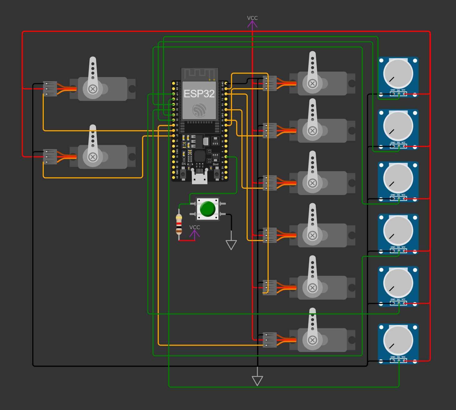
HERO SHOT! Wokwi simulation.
LEARNINGS
This week, Wokwi proved to be an essential tool for testing and refining my ESP32-WROOM code before moving to physical hardware. It allowed me to simulate GPIO control, ADC readings, PWM, and interrupts in a controlled environment, making debugging and optimization much more efficient.
Even with prior experience in microcontrollers and C++, using Wokwi streamlined the development process, reducing potential hardware-related issues. It reinforced how valuable simulations can be for embedded systems, especially when testing real-time tasks and multiple interactions simultaneously.
