Computer-Controlled Cutting
Computer-Controlled Cutting refers to the use of CNC (Computer Numerical Contro) machines to cut, engrave, or shape materials based on digital vector designs. The CNC follows precise instructions from software-generated toolpaths, ensuring accuracy and repeatability.
In this case, I will focus on laser cutters and vinyl cutters, as both are available at the university:
Laser Cutters
Laser cutters use a high-powered, focused laser to precisely cut or engrave materials like wood, acrylic, and certain metals by burning or vaporizing the surface along a programmed design. This method ensures clean, accurate cuts and supports a variety of materials and thicknesses.
Laser cutter key components
- Unfocused Laser Beam: The initial low-power beam emitted from the laser source before being concentrated.
- Focal Length: The distance between the focusing lens and the point where the laser converges for maximum intensity.
- Focusing Lens: A lens that concentrates the laser beam, increasing its power for effective cutting.
- Nozzle: Directs the focused laser beam onto the material, ensuring precision.
- Focused Beam: The high-energy beam that exits the nozzle, strong enough to cut or engrave materials.
- Focal Spot: The exact point where the laser achieves optimal cutting efficiency.
- Depth of Focus: The range within which the laser remains properly focused, affecting the quality of the cut.
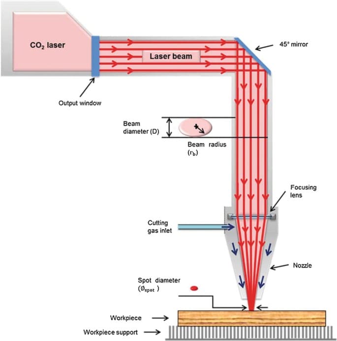
Figure 1: Laser cutter key components.
Maintaining the correct focal distance is critical, as improper calibration can lead to inconsistent cuts, burning, or reduced efficiency. For this week, I will be using a CFL-CMA1390T CO₂ laser cutter, which features:
| Specification | Details |
|---|---|
| Work Area | 1.30 x 0.90 meters |
| Work Table | Honeycomb |
| Accessory | Double Tube |
| Cutting Speed | 0-36,000 mm/min |
| Engraving Speed | 0-64,000 mm/min |
| Power | 100 Watts |
| Cutting Thickness | 0-25 mm |
Unlike fiber or diode lasers, the CO₂ laser source is positioned behind the machine, requiring mirrors to redirect the beam to the cutting head. Because the laser path is not enclosed, any interference can result in burns, and direct contact must be avoided at all times. For detailed information on materials, applications, and additional specific laser cutter parameters, visit our group page.
A key consideration from the Group Assignment, it's crucial to account for kerf, the material removed by the laser during cutting. In our case, the measured kerf was approximately 0.15mm, which will be factored into the design. However, using this exact value results in a very tight fit, making assembly difficult. To ensure a practical and secure fit, I will adjust the kerf to 0.2mm for my designs.
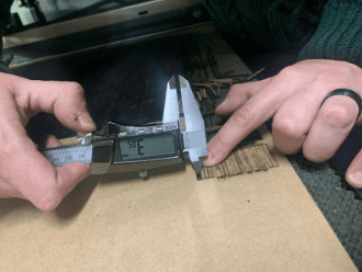
Figure 2: Kerf Measurement.
Before starting parametric design, here are some instruccions and considerations for the use of the laser cutter:
- Powering On the Machine: Turn on the regulator and power switch, then release the emergency stop button to activate the machine. Finally insert and turn the key
- Understanding the Control Panel: Use the D-pad to move the laser along the X and Y axes, press the center button for Z-axis adjustments, set the cutting origin with the "Origin" button, and adjust laser intensity using the knob.
- Calibrating the Laser: Ensure the laser is off for safety, loosen the holding screw, adjust the laser height (5mm from the material), then tighten the screw.
- Importing and Preparing the Design: Open the cutting software, import the DXF file, assign cutting parameters using colors, and set the unused laser to 0 power if using only one.
- Setting Up the Cutting Process: Transfer the file to the cutter via USB, press the "File" button to locate and copy the file, and ensure it appears on the machine's screen.
- Checking the Cutting Area: Press "Frame" to preview the laser’s movement and verify it fits within the material’s margins.
- Executing the Cut: Close the laser cutter lid for safety, turn on the laser power button, and press "Start" to begin cutting.
- Post-Cutting Safety: Once cutting is complete, turn off the laser immediately and wait for it to fully stop before removing the material.

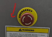
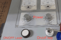
Figure 5: Energy control panel, Turn the key.
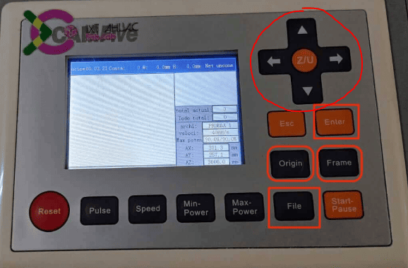
Figure 6: Control panel.
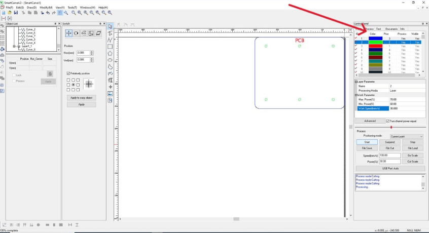
Figure 7: SmartCarve starting menu.
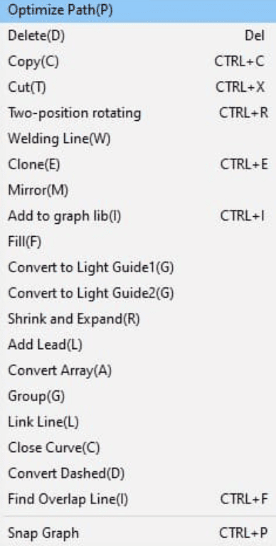
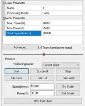
Parametric Design
For my parametric design, I initially wanted to create a Lego-style set that would allow for endless shape possibilities with enough pieces. However, I aimed to make it even more versatile than traditional Lego.
After analyzing multiple FAB models from previous years, designs from my colleagues, and online references, I noticed that most followed a fixed connection measurement they predefined. While this approach works, I questioned, what if the connection size adapted to the material itself?
Ultimately, I decided to base all dimensions on the thickness of the material (in this case, MDF). This approach allows not only for predefined joints but also gives the user freedom to explore more creative and flexible assemblies. While it may not offer the same structural firmness as Lego, it provides a more open-ended and adaptable construction method. Additionally, since the pieces are made from an affordable material, experimentation is encouraged; if a piece breaks, it can be easily and cheaply replaced.
Here is my initial design concept for my kit:
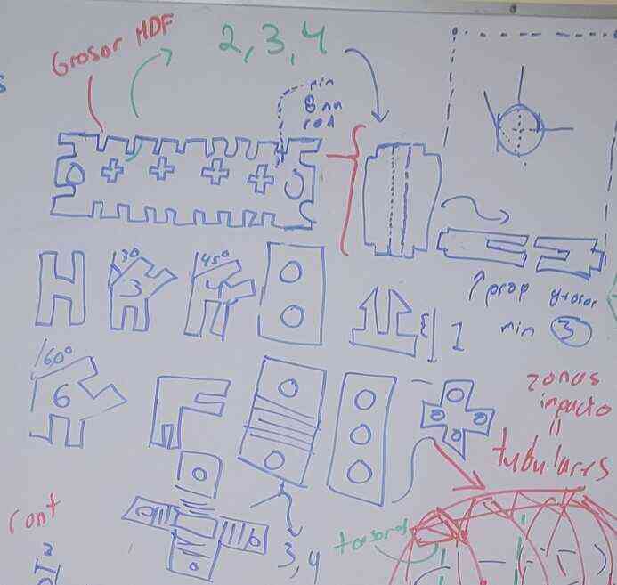
Figure 10: Initial design.
I should clarify that, due to time constraints, I was unable to incorporate snap-fit joints, which would have given more purpose to the circular holes. However, these holes were also designed to function as hinges, so they still have a more useful and different purpose.
Additionally, I chose not to implement flexible joints, as I prioritized progress on my final project. Given that my parametric design allows for angular joints, flexible pieces weren’t entirely necessary. However, for those interested, I highly recommend exploring their design, as integrating them could further enhance both versatility and aesthetics, improving the overall adaptability of the kit.
With these clarifications in mind, I will now present my parametric designs. Also, to download the documents, go to the end of the page...
Main piece
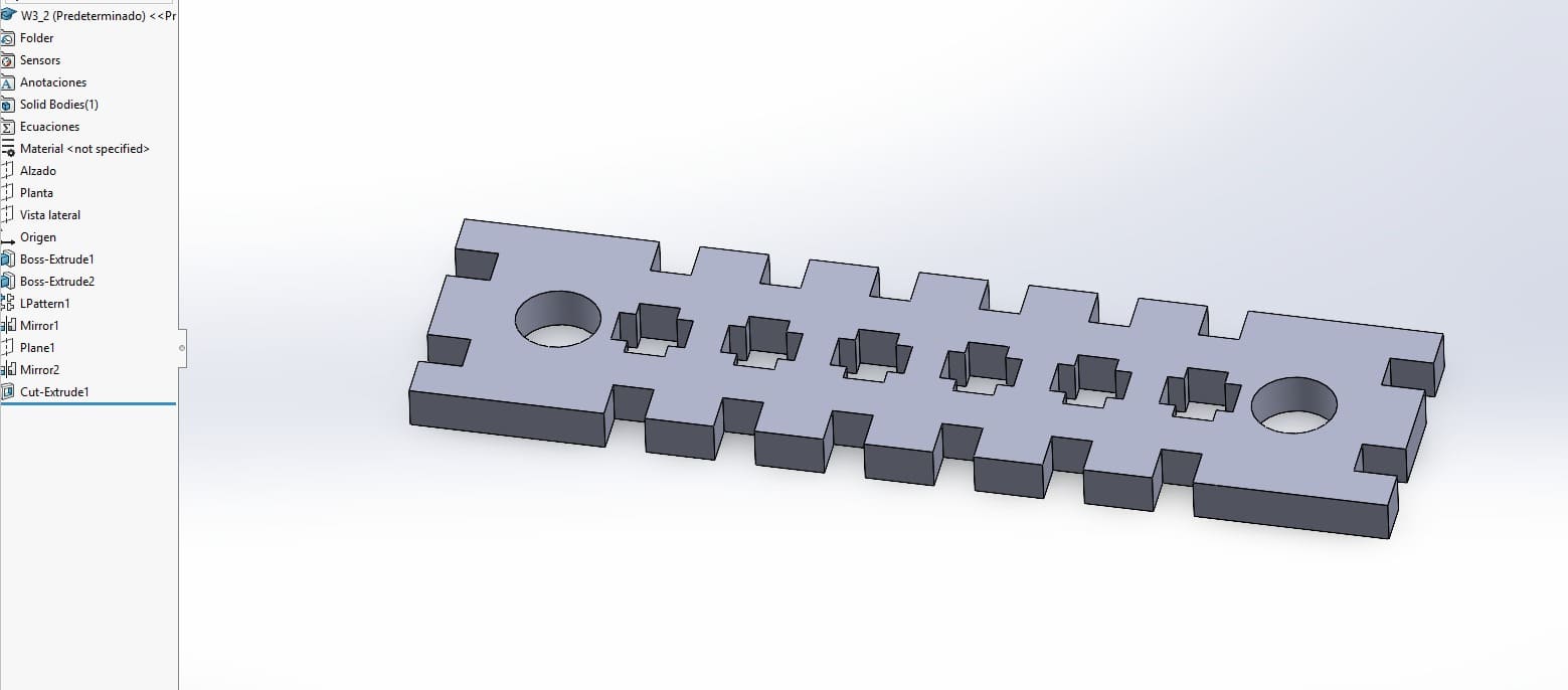
Figure 11: Main piece.
Before describing the process, I want to highlight a key issue with this piece. Initially, I couldn’t fully close the sketch when including the entire design due to the use of linear patterns and mirror functions within the sketch. To work around this, I used SolidWorks' 3D tools to apply patterns and mirrors after extrusion, allowing me to extract the DXF from one side of the solid model.
While this approach worked, it introduced a limitation: when modifying parametric data, the entire piece adjusts except for the mirrored edge. This occurred because SolidWorks did not allow me to assign a variable to the plane distance used for the mirror, requiring manual adjustments when changing parameters. However, aside from this issue, the rest of the part scales correctly according to the parametric values.
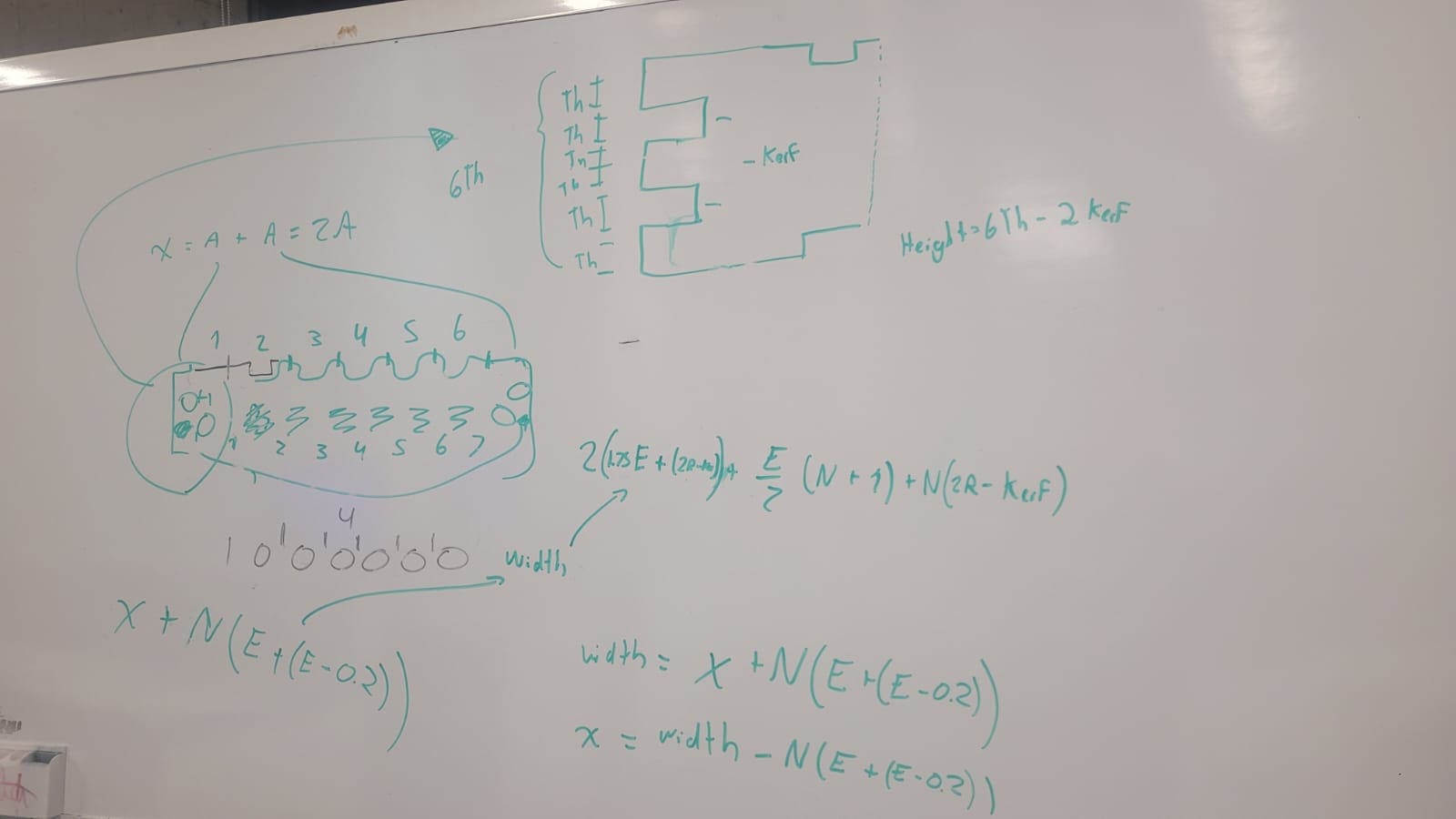

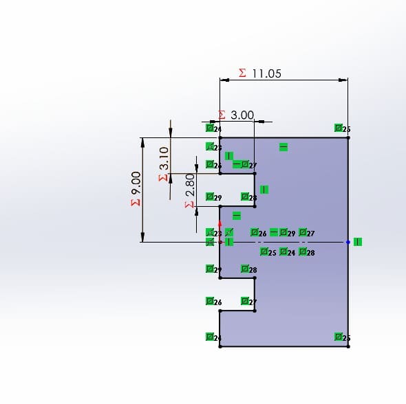
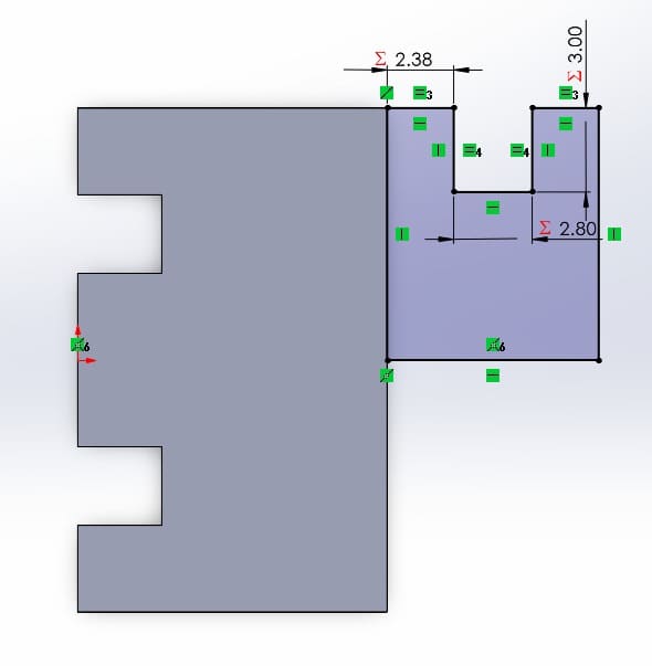
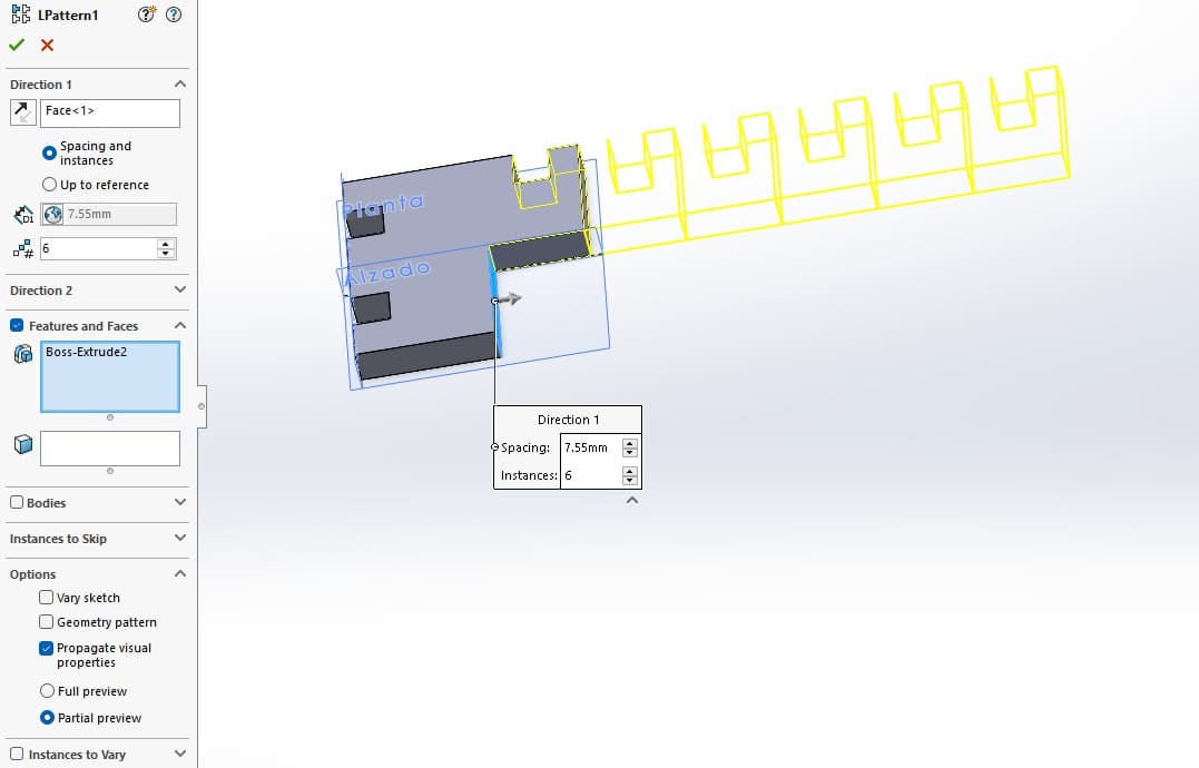
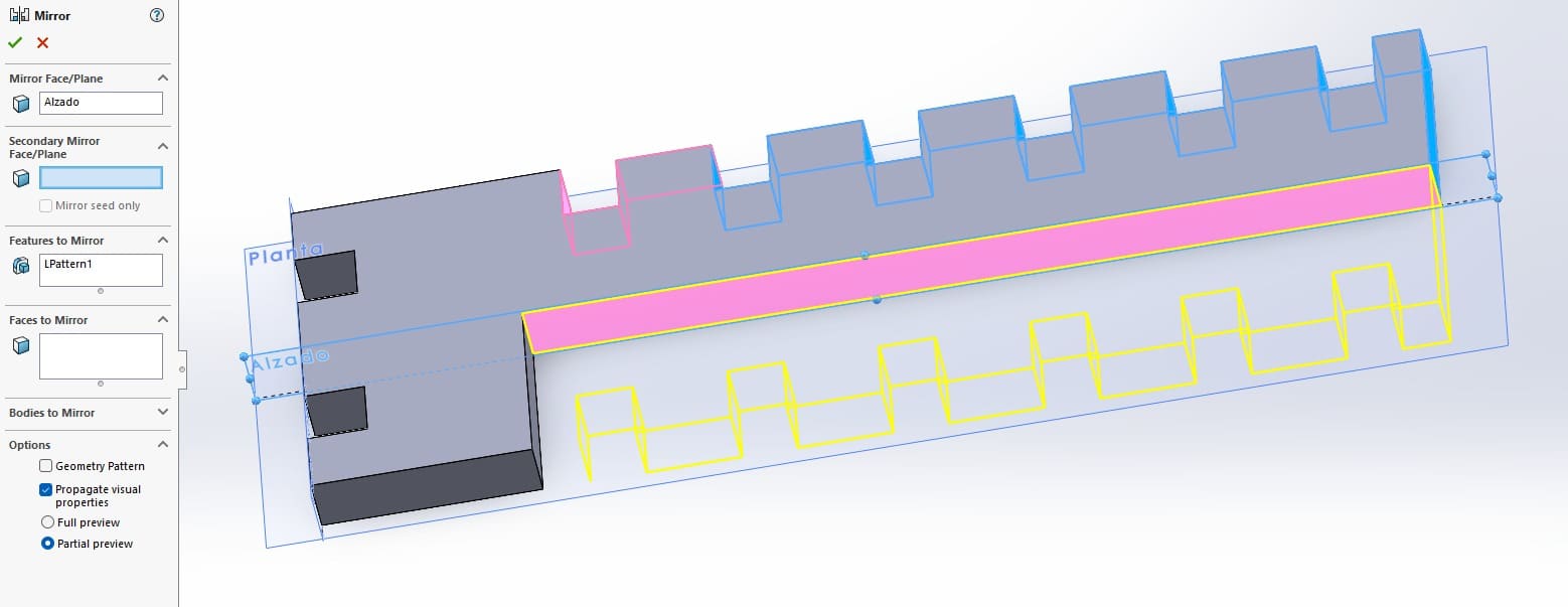
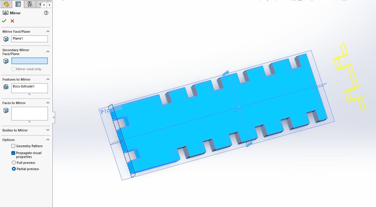
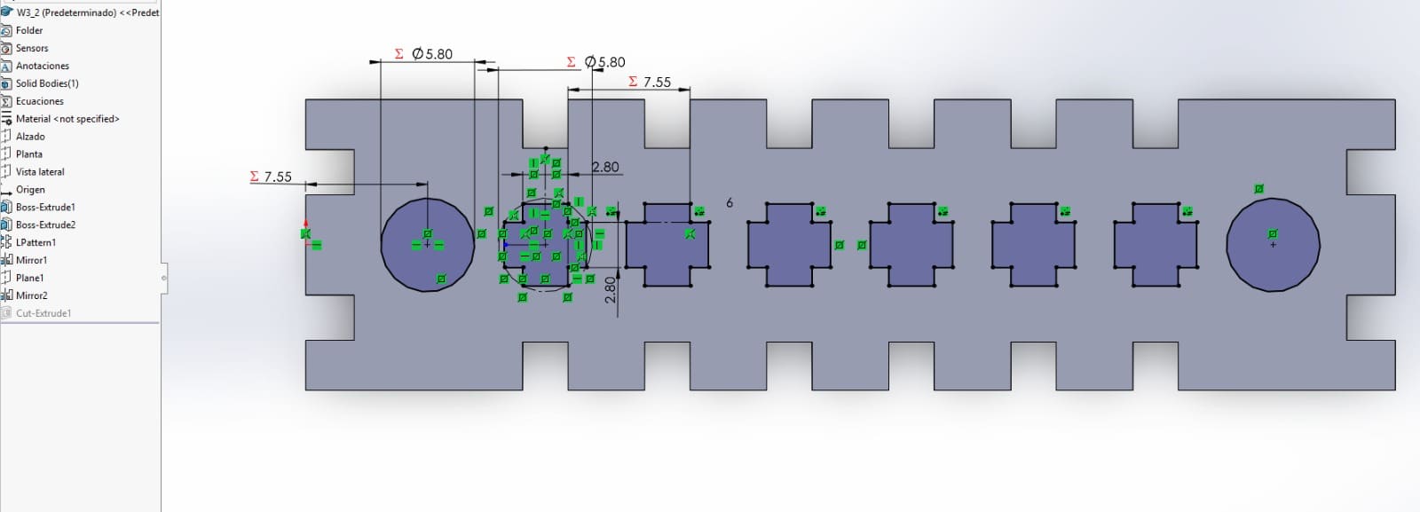


Excluding the previously mentioned plane limitation, the piece can now be fully adjusted based on the variable parameters set in SolidWorks. For instance, since my design requires multiple pieces of varying lengths, I can modify this using the "Block_Width" variable. This not only adjusts the length but also automatically updates the number of holes in the piece. Once the necessary changes are made, I can simply export the design as a DXF file, making it ready for laser cutting.
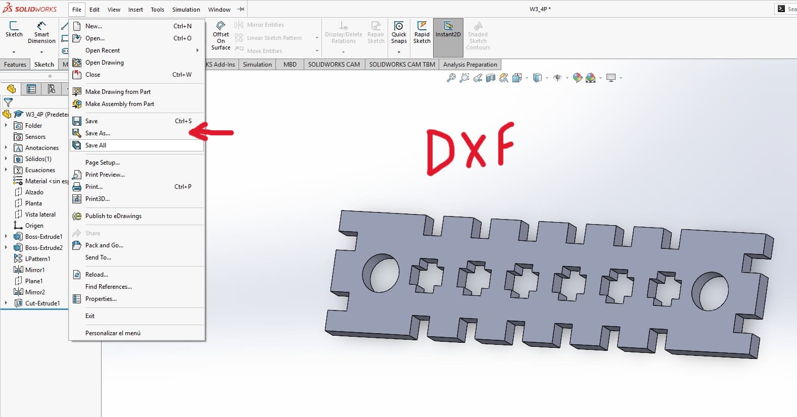
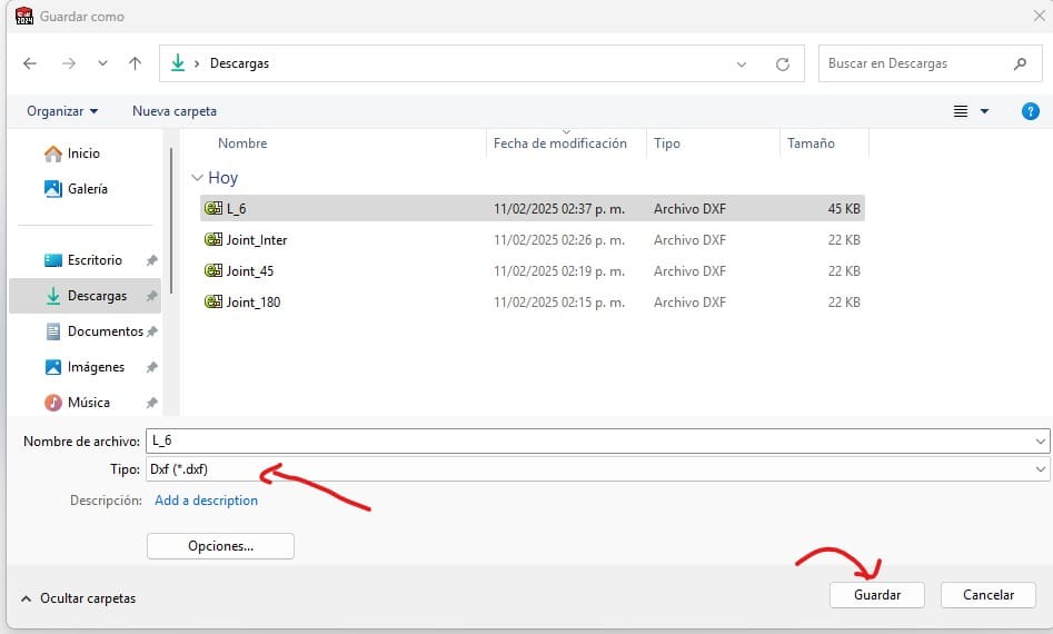
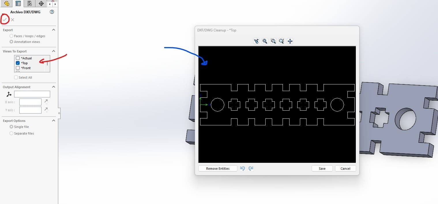
Figure 24: DXF solidworks menu.
Expanding on the initial design, I explored different types of joints that would enable both simple and more complex assemblies while maintaining an organized structure. To achieve this, I designed small connector pieces that facilitate the assembly of either additional joints or base pieces from the existing set. The two most essential types of connectors I identified were:
- Directional/Angular Connectors: These pieces allow adjustments in assembly direction or angle, expanding design possibilities.
- Support Pieces: Used to bridge large distances, reinforce structures, and even function as hinges by utilizing the existing holes in the base pieces.
From these considerations, I developed the following parametric designs.
Angular Connectors
This parametric design is not just about modifying dimensions, it primarily focuses on creating a variable angle joints. Thanks to its parametric adaptability, users can simply input the desired angle (preferably between 0-90°) to customize the connection between pieces, offering greater flexibility in assembly.

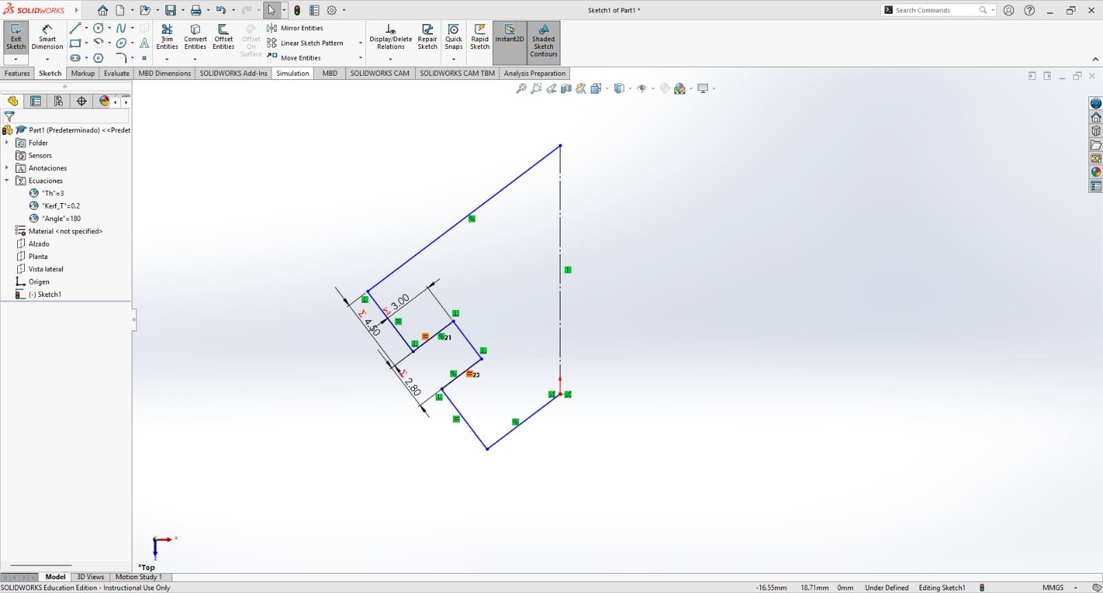
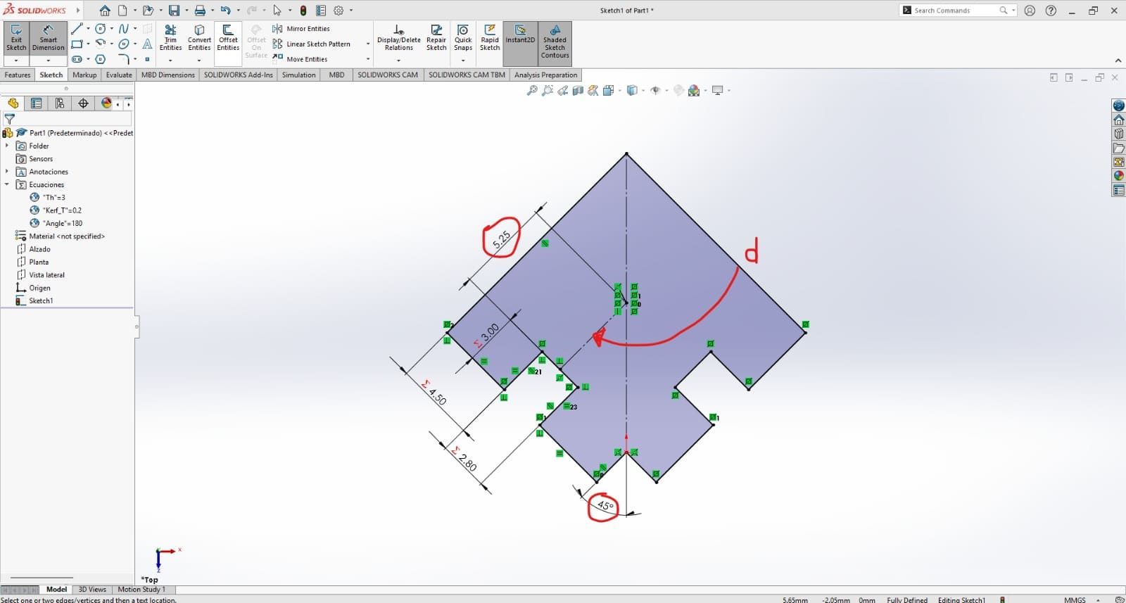
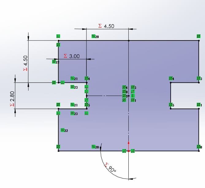
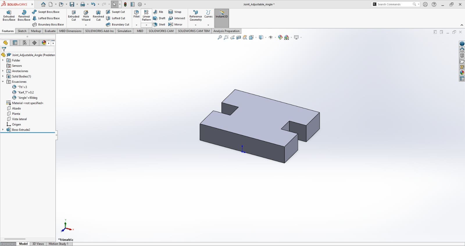
Figure 29: Extrude the piece.
Support Pieces
Although designed primarily for structural support, this piece can also serve as a versatile connector, thanks to the kit’s material-thickness-based design. Its parametric functionality allows it to span large distances, with its main adjustable parameter being height. Additionally, to enhance its structural integrity, it features a central slot, enabling assembly with another identical piece or integration into other practical configurations.
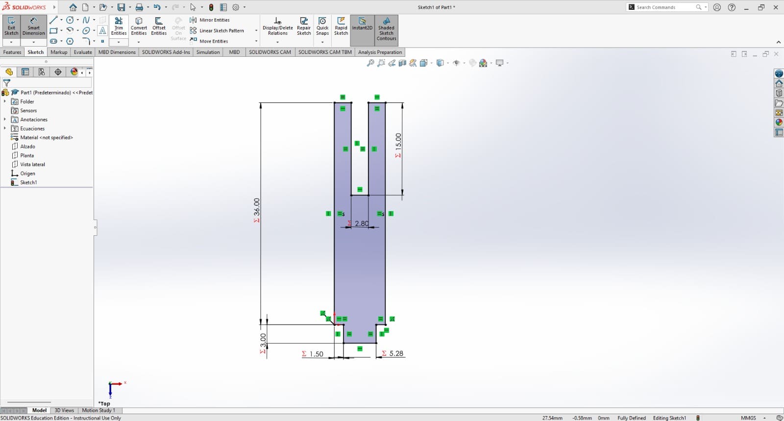
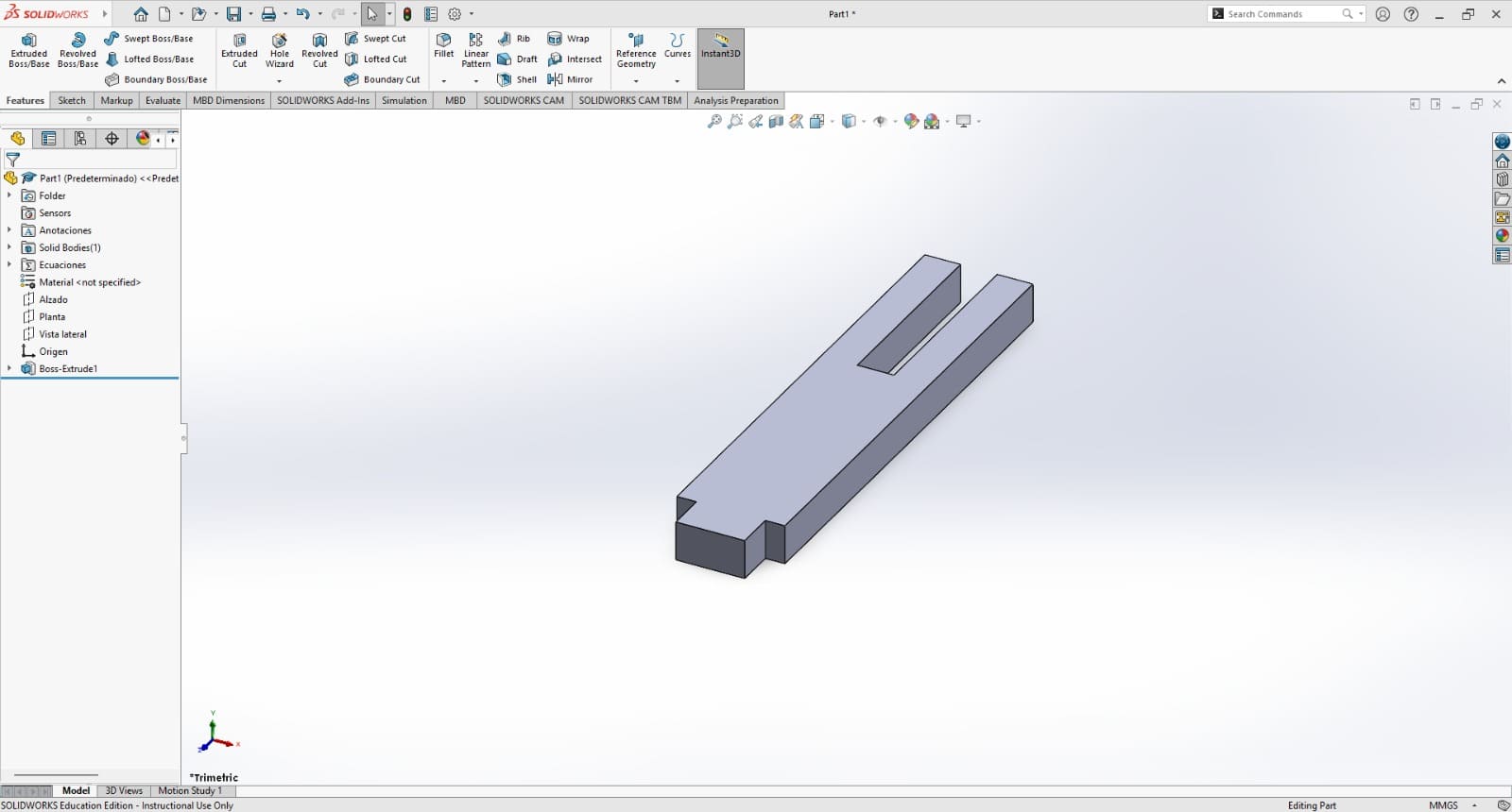
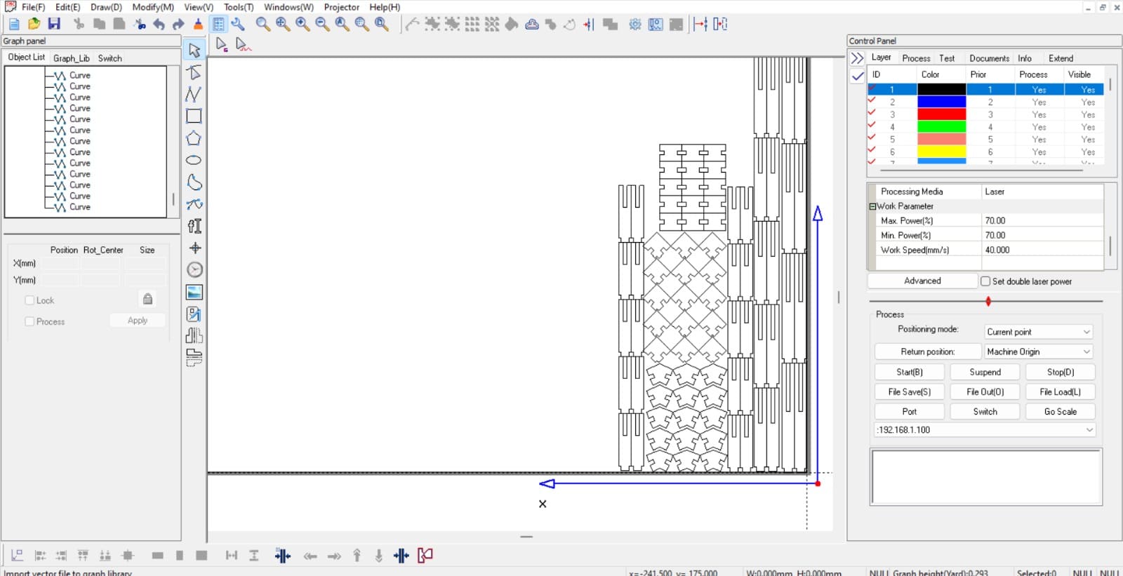
After designing, the next step is to cut test samples of each piece to evaluate their fit and assembly compatibility. The laser cutting parameters applied to all cuts were: Power, 70% (both max and min); and Speed, 40 mm/s.
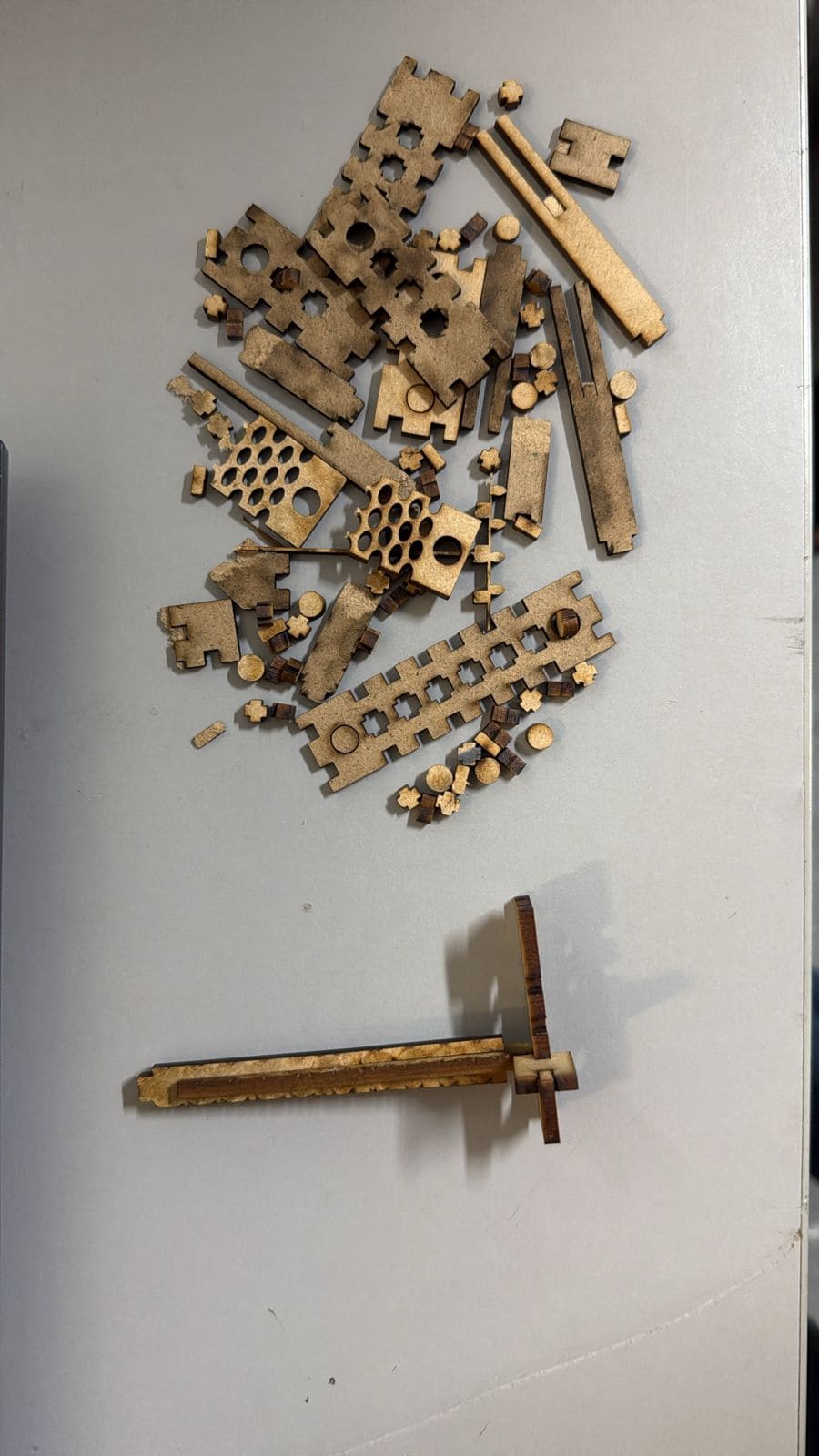
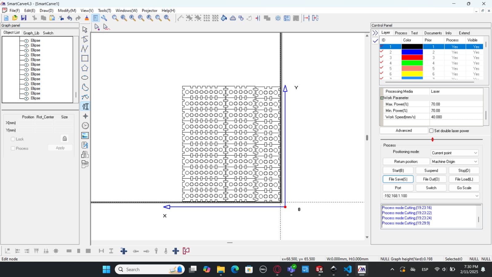
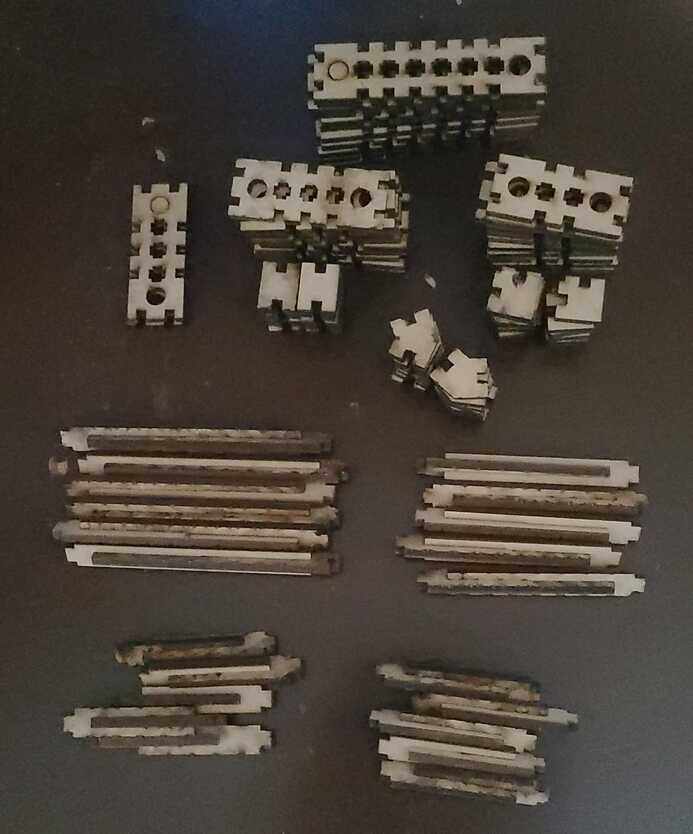
One observation I have to make, I was informed that the laser was slightly damaged, though still functional for cutting. As a result, some cuts were not as precise as expected, but the issues were minor and did not significantly impact the overall outcome.
After 30 minutes of assembly and debating what to desing with the pieces, the following came out:
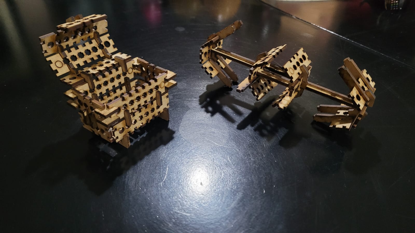
HERO SHOT! Chest and star wars fighter spaceship (?).
Vinyl Cutter
Vinyl cutters use a small precision blade to cut thin materials like adhesive vinyl, paper, and heat transfer film. They are widely used for aesthetic purposes, such as stickers, signage, and custom decals, as well as for technical applications, including component labeling, circuit masking, and precision stenciling in prototyping.
- Digital Design: The design is created using vector-based software such as Adobe Illustrator, Inkscape, or the cutter's proprietary program. It must be in a compatible format like SVG, DXF, or AI.
- Material Preparation: The vinyl is cut to the required dimensions for the job. The backing paper is cleaned to remove any dust or residue that could affect precision. If needed, adhesive is applied to the backing paper (a gridded sheet that helps during cutting).
- Machine Setup: The vinyl is then loaded, and parameters such as pressure, speed, and blade depth are adjusted based on the material type.
- Vinyl Cutting: The machine moves the material while the blade follows the vector paths, cutting only the top layer of vinyl without damaging the backing paper.
- Weeding: Unwanted vinyl is carefully removed using tweezers or hooks, leaving only the desired design.
- Application of Transfer Tape: A special adhesive tape is applied over the cut vinyl, allowing it to be transferred to the final surface while maintaining its shape and alignment.
- Placement on the Final Surface: The design is positioned onto the chosen surface (glass, metal, wood, plastic, etc.), and pressure is applied with a squeegee to ensure adhesion and eliminate air bubbles.
- Removal of Transfer Tape: The transfer tape is slowly peeled away, leaving the vinyl securely attached to the surface.
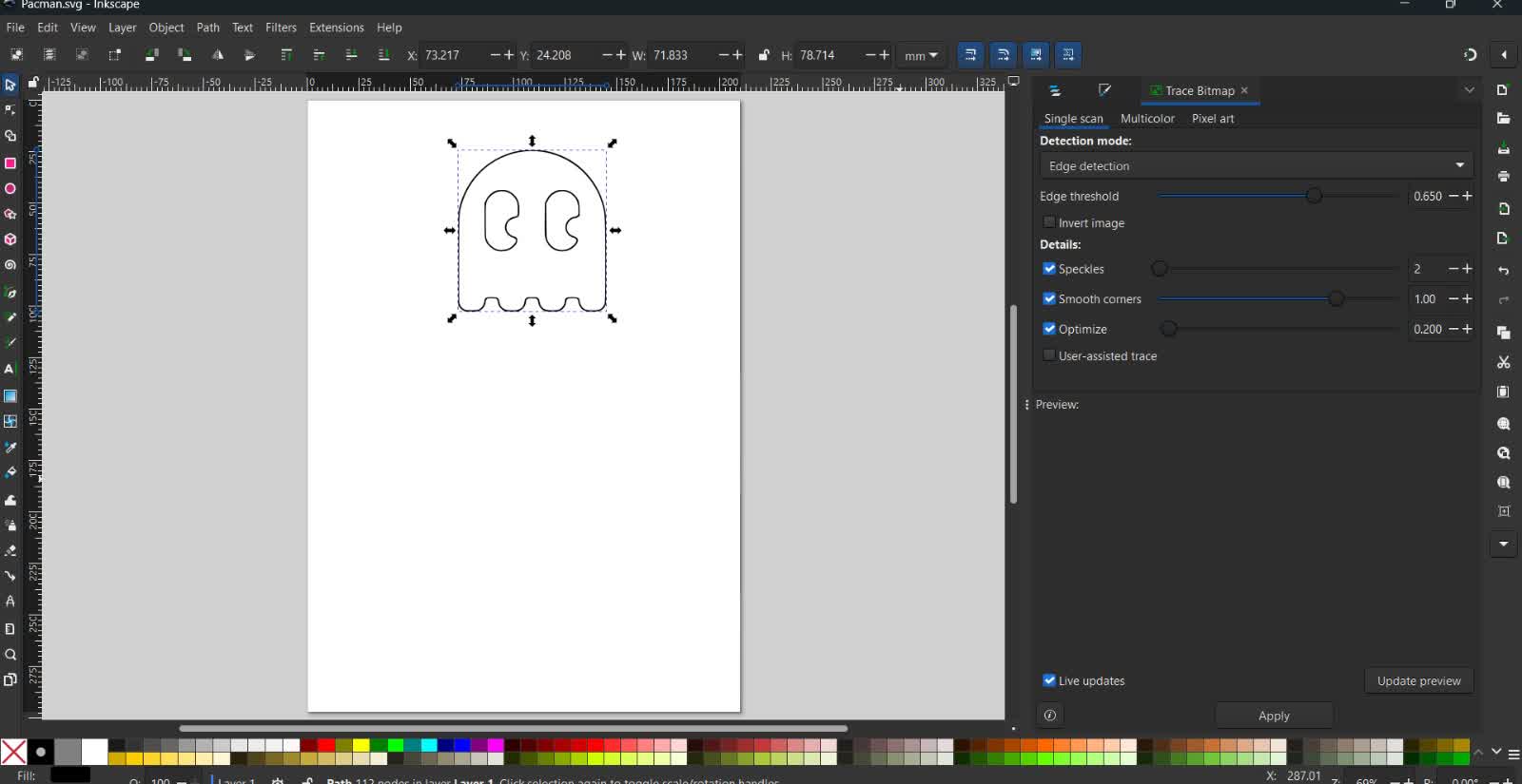
Figure 36: Vectorizing the image in inkscape.
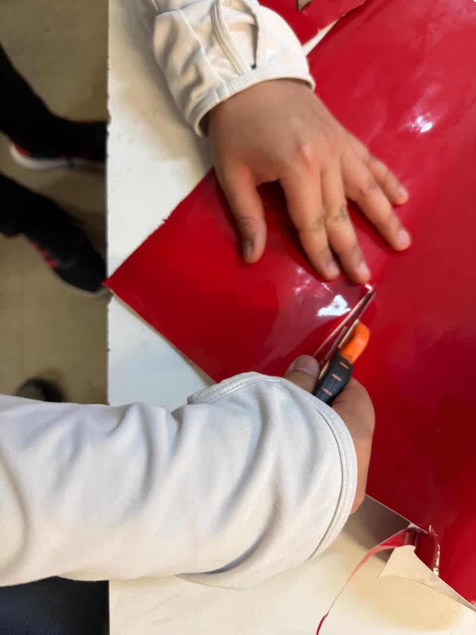
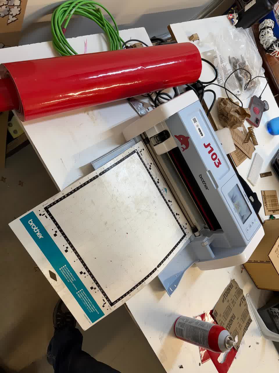
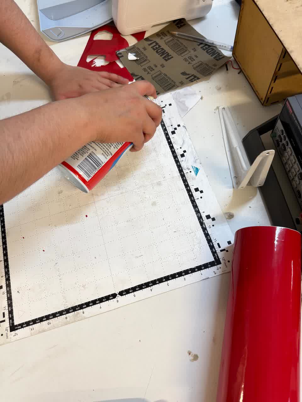
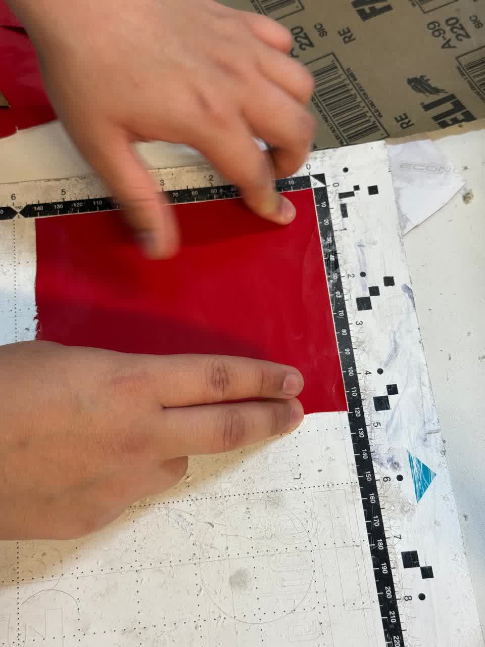
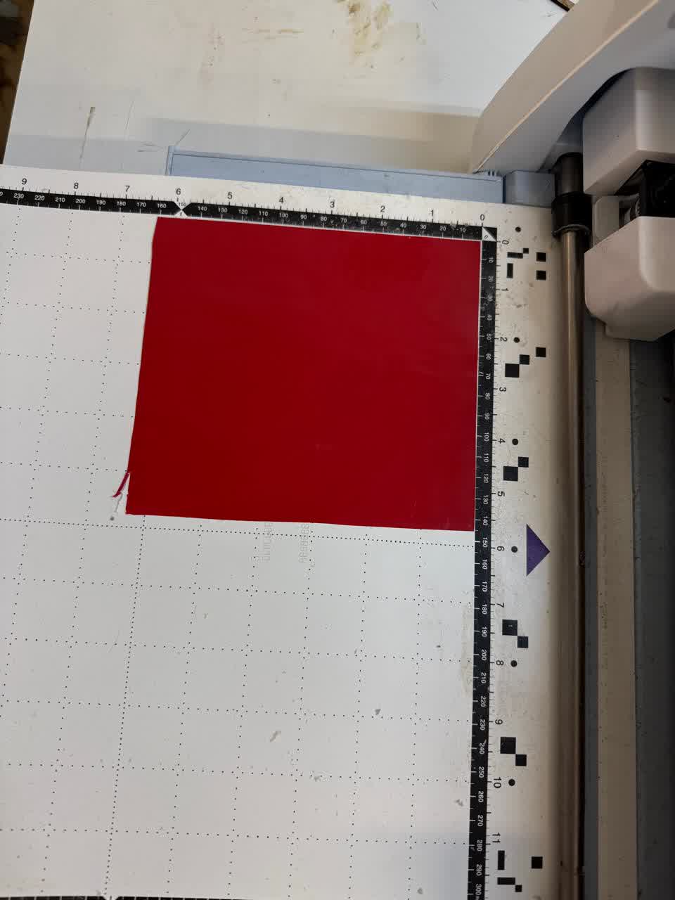
Figure 41: Loading the vinyl to the machine.
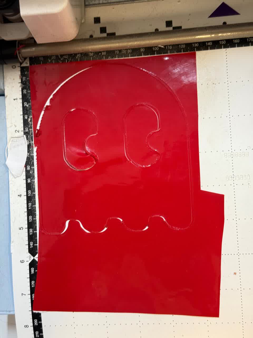
Figure 42: Vinyl cutting results.
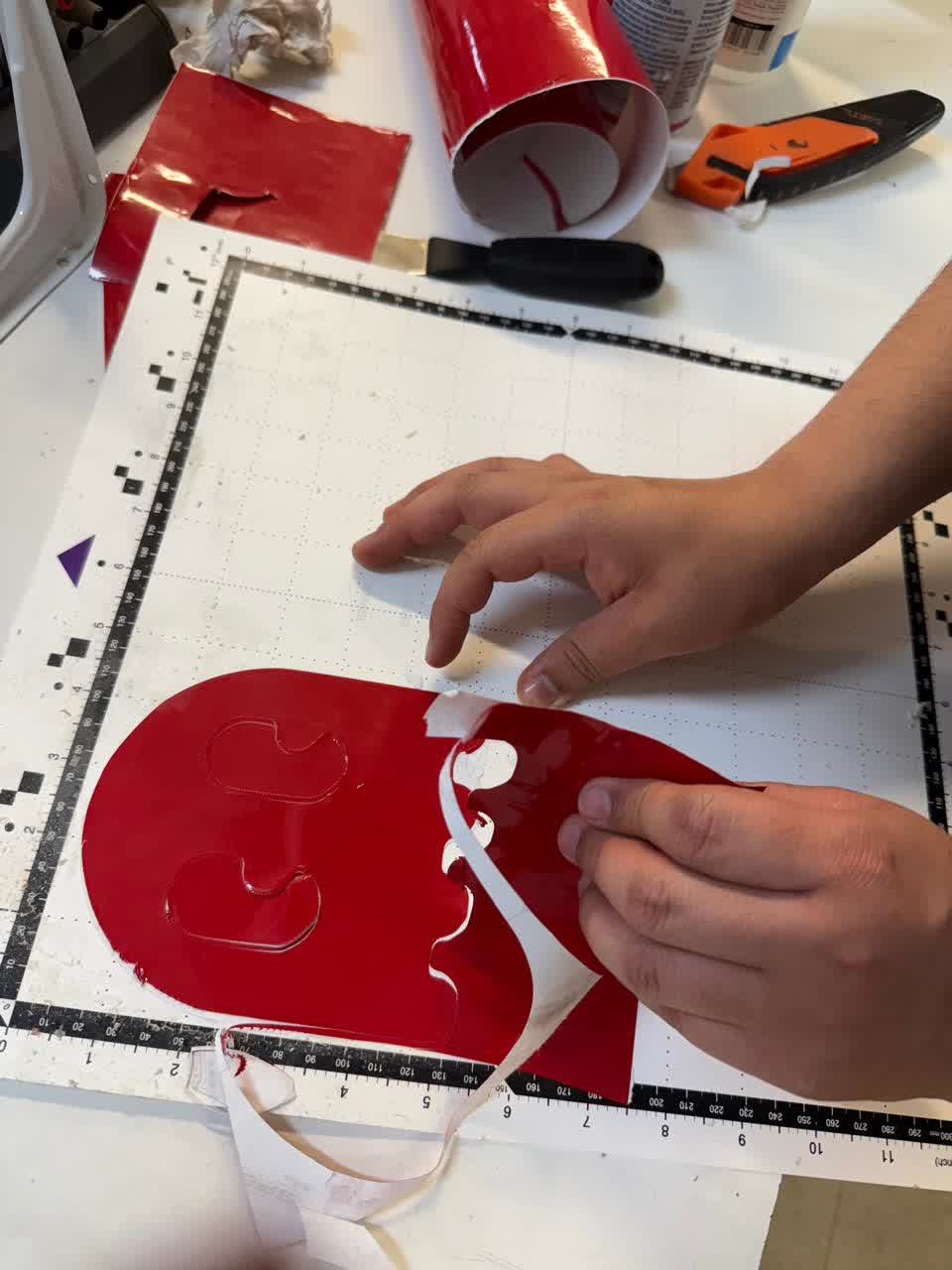
Figure 43: Removing unwanted vinyl.
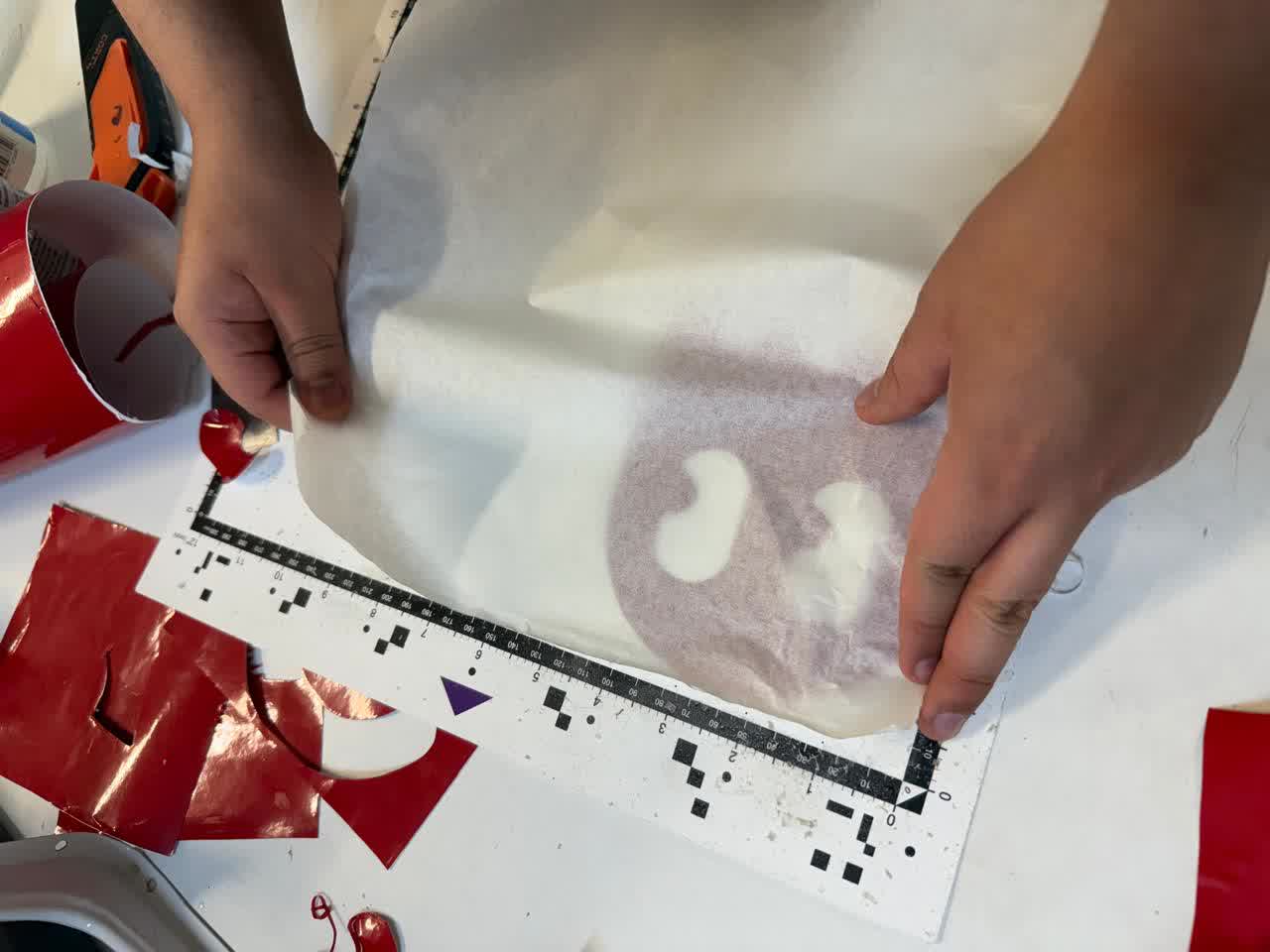
Figure 44: Applying transfer tape.
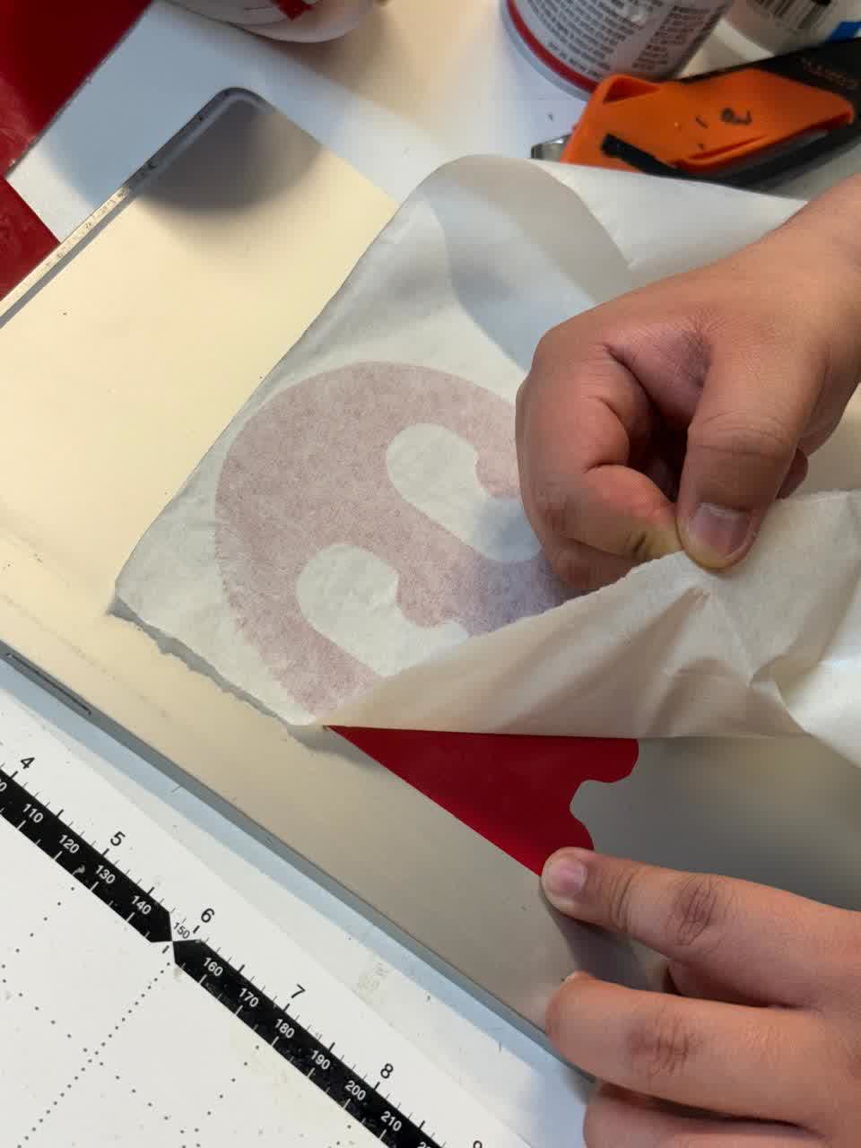
Figure 45: Removing transfer tape.
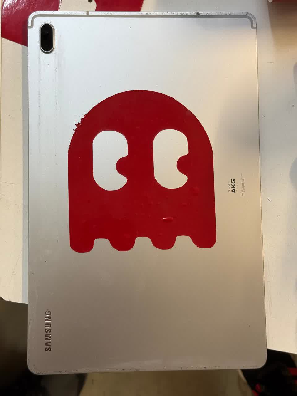
Figure 45: Results.
LEARNINGS
In summary, this week, in addition to improving my proficiency with well-known software tools such as SolidWorks, I also gained experience using Inkscape and Fusion 360, at least for my specific needs. Mastering CAD software like SolidWorks, Fusion 360, and Inkscape enhances control over prototyping and manufacturing, making the design process more efficient and precise.
Additionally, working with computer-controlled cutting gave me hands-on experience with both laser and vinyl cutting, reinforcing the importance of parametric design and proper machine calibration. I learned how laser kerf affects part fitting and why adjusting tolerances is crucial for assemblies. Vinyl cutting helped me understand the need for precise vector designs and the challenges of handling delicate materials. Beyond software, this week highlighted how machine settings, material properties, and testing iterations all play a role in achieving accurate and reliable fabrication results.
