Computer Aided Design
CAD (Computer Aided Design) is used to create both 2D and 3D technical designs. In 2D, it helps make drawings, views, measurements, schematics, and CNC cutting layouts. In 3D, it allows designing parts, assembling components, simulating motion, rendering images, and analyzing stress and forces.
First, I will use a 2D CAD program to demonstrate how to vectorize an image in Inkscape. After that, I will switch to a 3D CAD to start modeling the first versions of the parts for the animatronic goose, which I am building as my final project. For the construction, I plan to design a universal fixable joint, allowing me to easily connect multiple aluminum tubulars and assemble the structure more efficiently.
INKSCAPE
Inkscape is a free and open-source vector graphics editor used to create and edit scalable designs. It works with SVG files and provides tools for tracing images, creating shapes, and editing paths.
In Inkscape, vectorization refers to the process of converting a bitmap (raster) image into a vector graphic, making it scalable without losing quality. Bitmap images (such as PNG or JPEG) are composed of pixels, meaning they become pixelated when resized. In contrast, vector graphics use mathematical paths (lines, curves, and shapes), allowing them to maintain sharpness at any scale. At this moment, I will demonstrate how to vectorize almost any image using the software.
First, before setting up the tools in the software environment, we need an image or file to vectorize. In this case, to create something relevant to the final project, I decided to design the logo for my animatronic. With the assistance of ChatGPT, I generated multiple images through a conversation until I found a suitable model for the logo.

Figure 1: Best AI generated logo idea.
Before we start, here is an image showing the location of the tools. For more info go to Inkscape Beginners' Guide
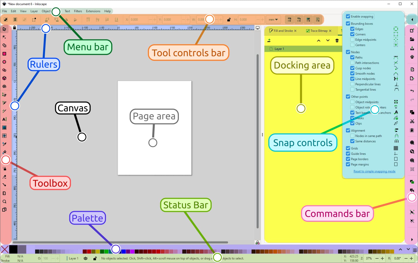
Figure 1 v2: Menu guide.
Once with the logo generated, we proceed to open Inkscape and import the image.
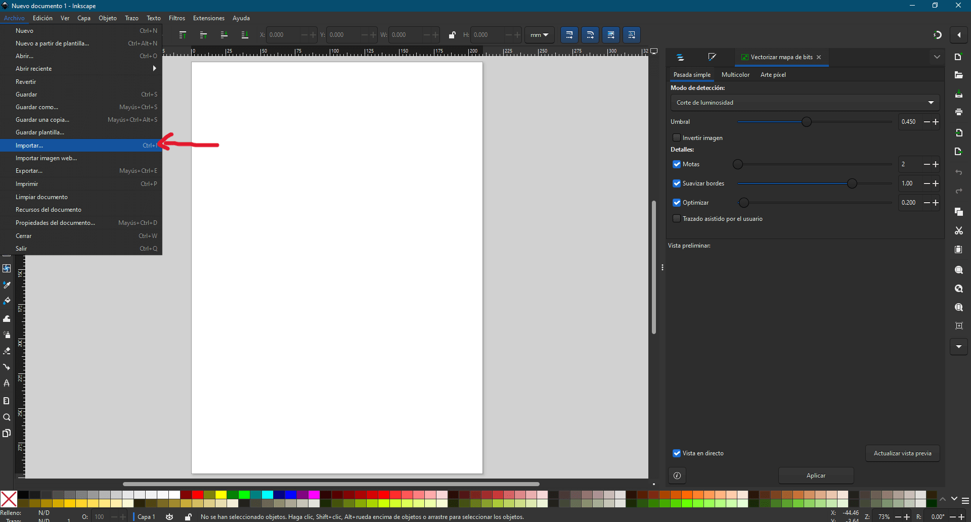
Figure 2: Import logo.
Inkscape provides a tool called "Trace Bitmap", which analyzes the pixel structure of a bitmap and generates a corresponding vector path. This tool operates using different methods, including:
- Brightness Cutoff: Converts pixels above a specific brightness threshold into vector shapes.
- Edge Detection: Identifies and traces high-contrast edges within the image.
- Color Quantization: Reduces the number of colors in the image and creates layers accordingly.
After that explanation, we locate the tools to generate the bitmap (vectorize the image) and, using the options in the menu, we proceed with the vectorization based on the selected method.
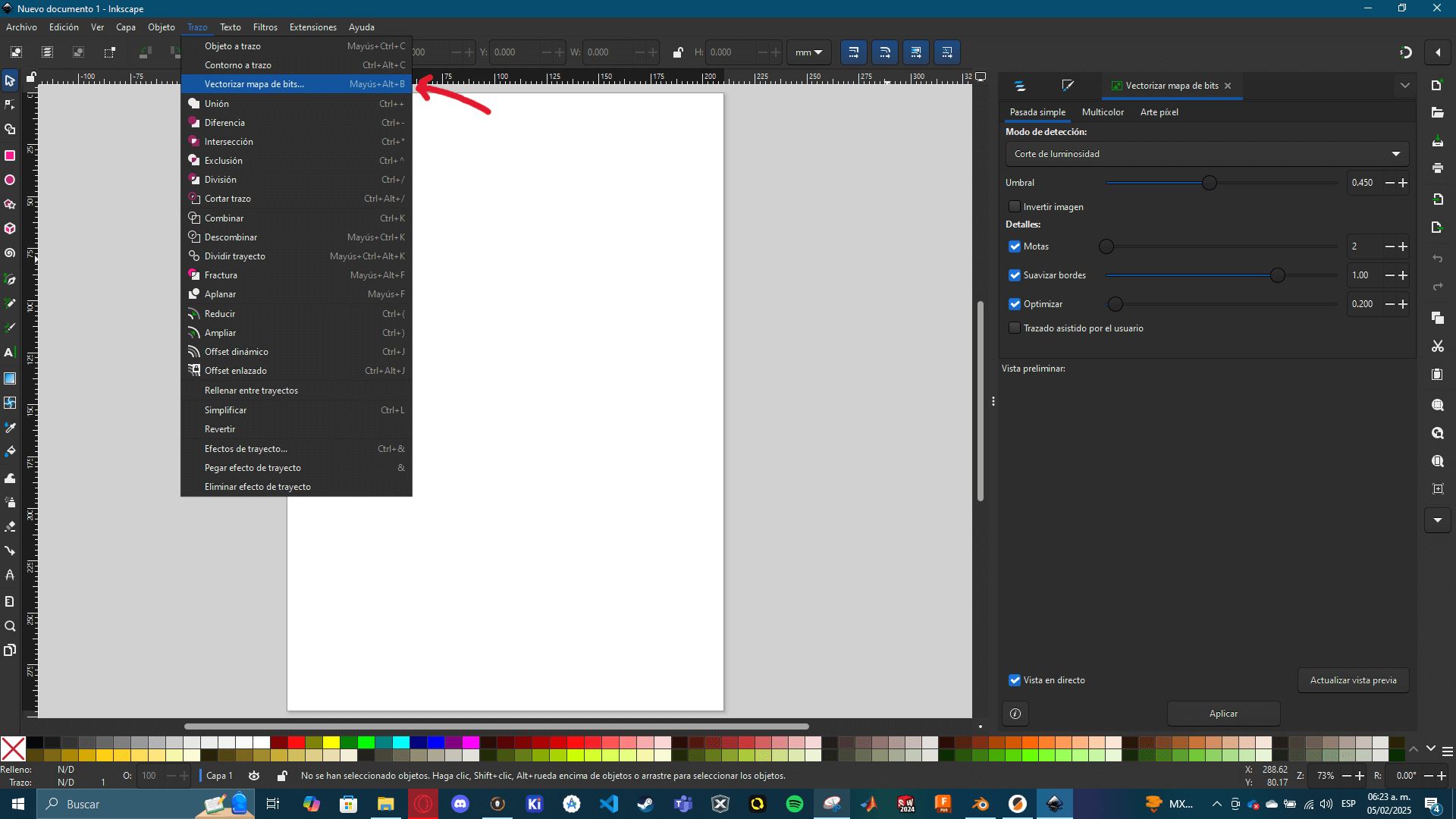
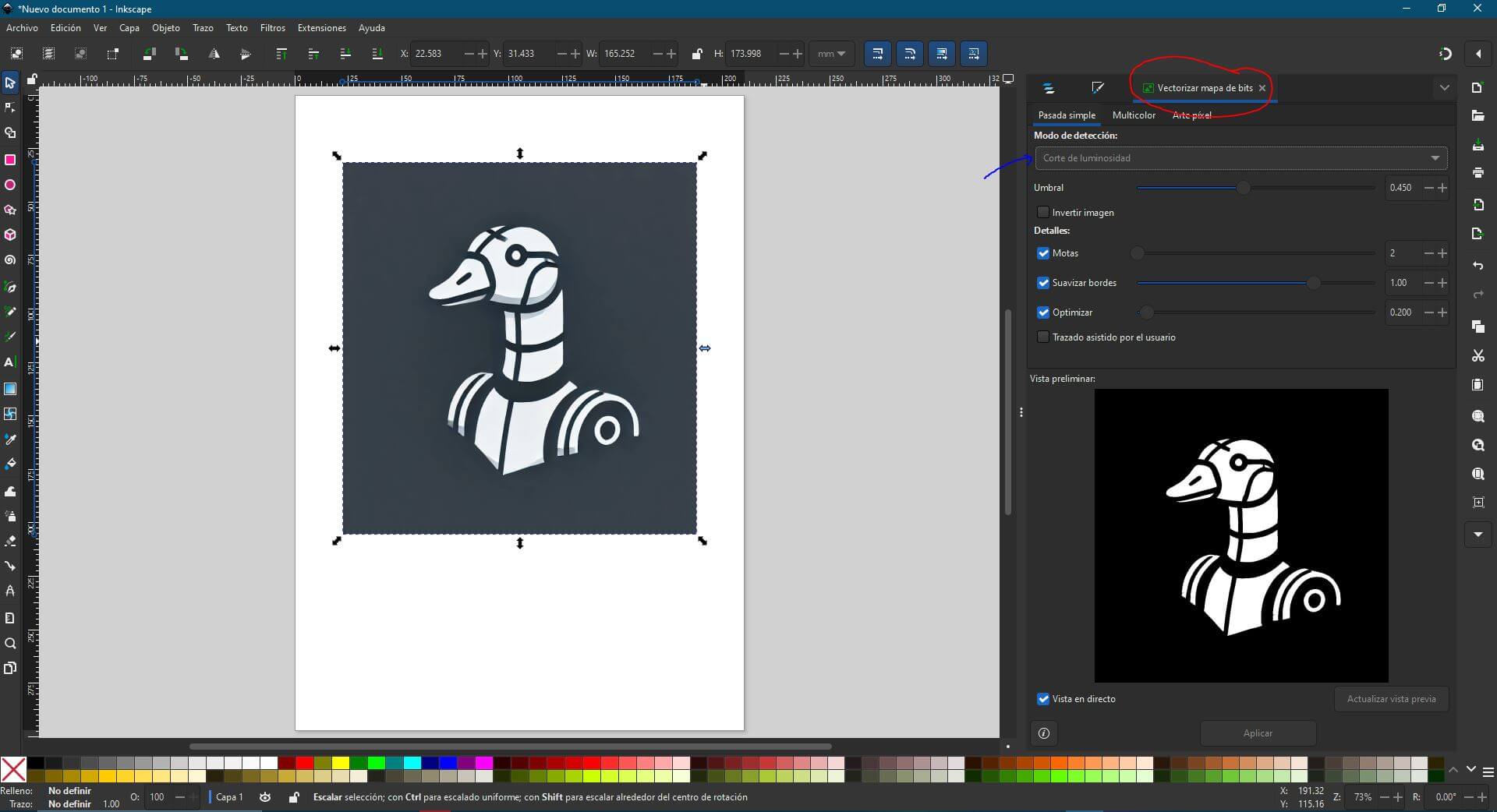
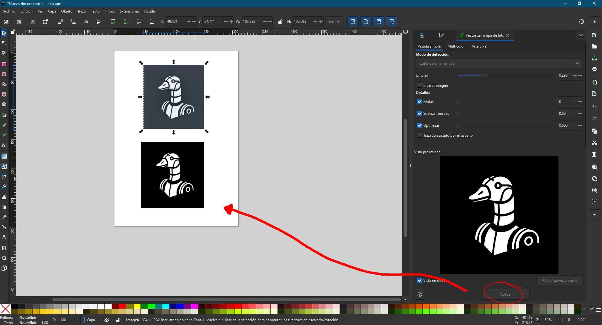
Figure 5: Comparison of results.
Vectorizing images in Inkscape is pretty easy!. In just a few steps, an image can be vectorized, allowing it to be rescaled freely without losing quality.
3D CADs
Unlike Inkscape, 3D CAD software is significantly more complex due to its wide range of tools. For this reason and beacuse my final project relies on 3D models, I want to focus more on 3D CAD in detail. Although each CAD software has its differences, most follow the same approach. Before creating a 3D model, it is necessary to start with a 2D sketch, which is then transformed using 3D tools. Additional operations can be applied later, whether for surface modeling or solid modifications.
To simplify the explanation, I will break down a general list of the most common and essential Sketch and Solid tools found in any CAD software.
| Sketch Command | Description |
|---|---|
| Line | Creates a straight segment between two points. |
| Circle | Draws a circular shape using a center point. |
| Rectangle | Creates a rectangular shape with two or three points. |
| Arc | Generates an arc using a center and two points. |
| Polyline | Combines multiple connected line and arc segments. |
| Polygon | Creates a multi-sided shape based on a center. |
| Offset | Generates parallel copies of lines or shapes. |
| Trim | Removes unwanted parts of a sketch. |
| Extend | Extends lines to meet another entity. |
| Mirror | Reflects sketch elements symmetrically. |
| Fillet | Rounds off sharp corners in a sketch. |
| Chamfer | Creates a beveled corner between two lines. |
| Convert Entities | Copies edges from 3D geometry into a sketch. |
| Constraints | Defines geometric relationships between sketch elements. |
| Smart Dimension | Adds measurements to sketch elements. |
| Solid Command | Description |
|---|---|
| Extrude | Creates a 3D solid from a 2D sketch. |
| Revolve | Forms a solid by rotating a sketch around an axis. |
| Sweep | Generates a solid by following a predefined path. |
| Loft | Creates a smooth transition between multiple profiles. |
| Fillet | Rounds off edges of a solid. |
| Chamfer | Adds a beveled edge between surfaces. |
| Shell | Hollows out a solid with a uniform wall thickness. |
| Cut-Extrude | Removes material from a solid using a sketch. |
| Hole | Creates different types of holes (countersunk, threaded, etc.). |
| Mirror | Reflects solid features symmetrically. |
| Circular Pattern | Repeats a feature around an axis in a circular array. |
| Linear Pattern | Duplicates features in a straight-line arrangement. |
| Boolean Operations | Performs union, subtraction, and intersection of solids. |
| Draft | Adds an angle to vertical faces for manufacturability. |
| Move/Copy | Relocates or duplicates solid bodies. |
In my case, I will use SolidWorks and Fusion 360. Both programs display their tools at the top of the interface, organized into sections based on their function. Additionally, hovering over a tool for a few seconds provides more information about its specific use.
SOLIDWORKS
In this software I will be designing the "universal joints" that will be connected both with my "universal node" (which I will design later in fusion 360) and will also be connected with the aluminum tubulars. In this software, I will be designing the universal joints, which will connect both to my universal node (which I will design later in Fusion 360) and to the aluminum tubulars.
First, we need to create a new sketch and draw a semicircle inside it. This semicircle will serve as the base for generating a sphere later.
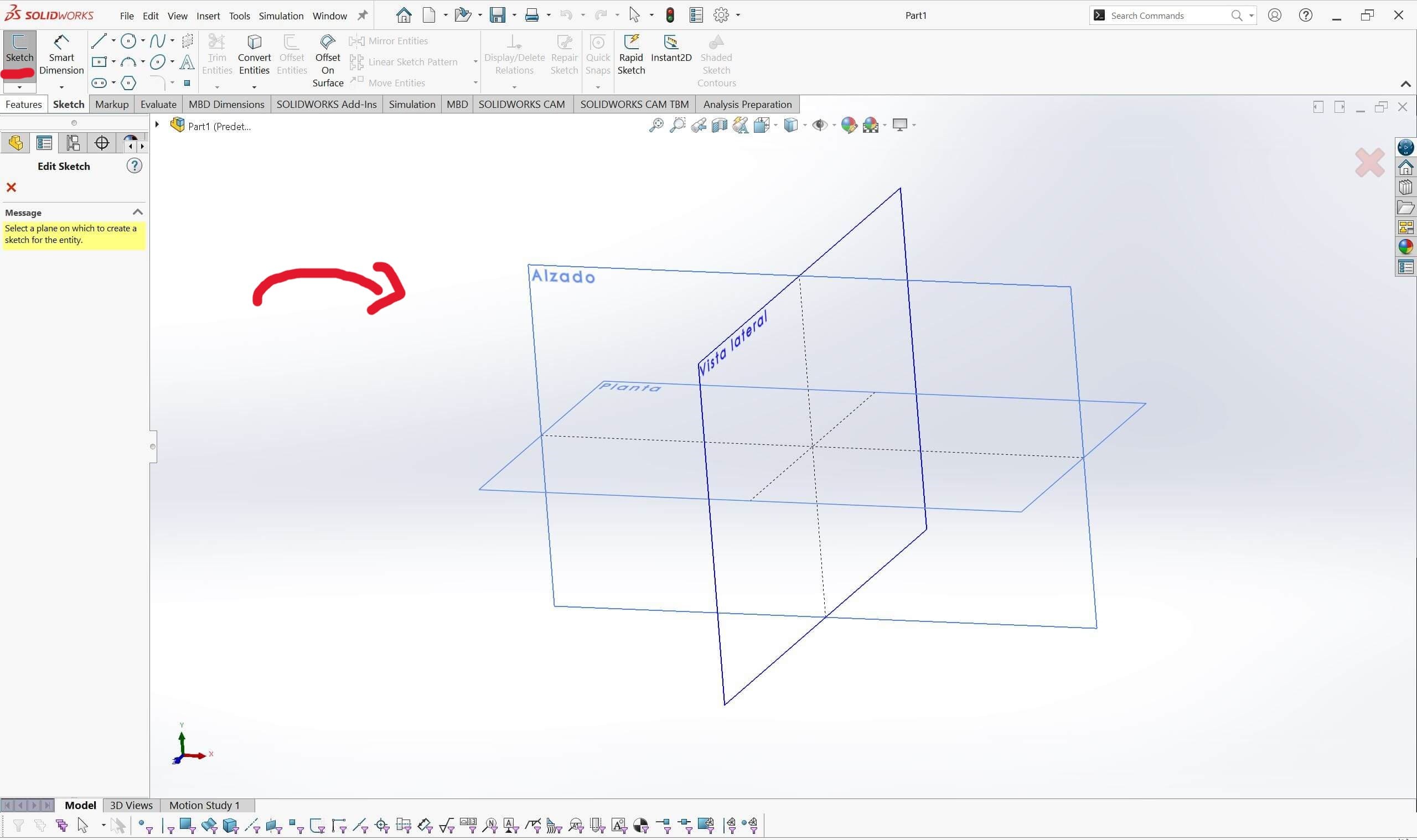
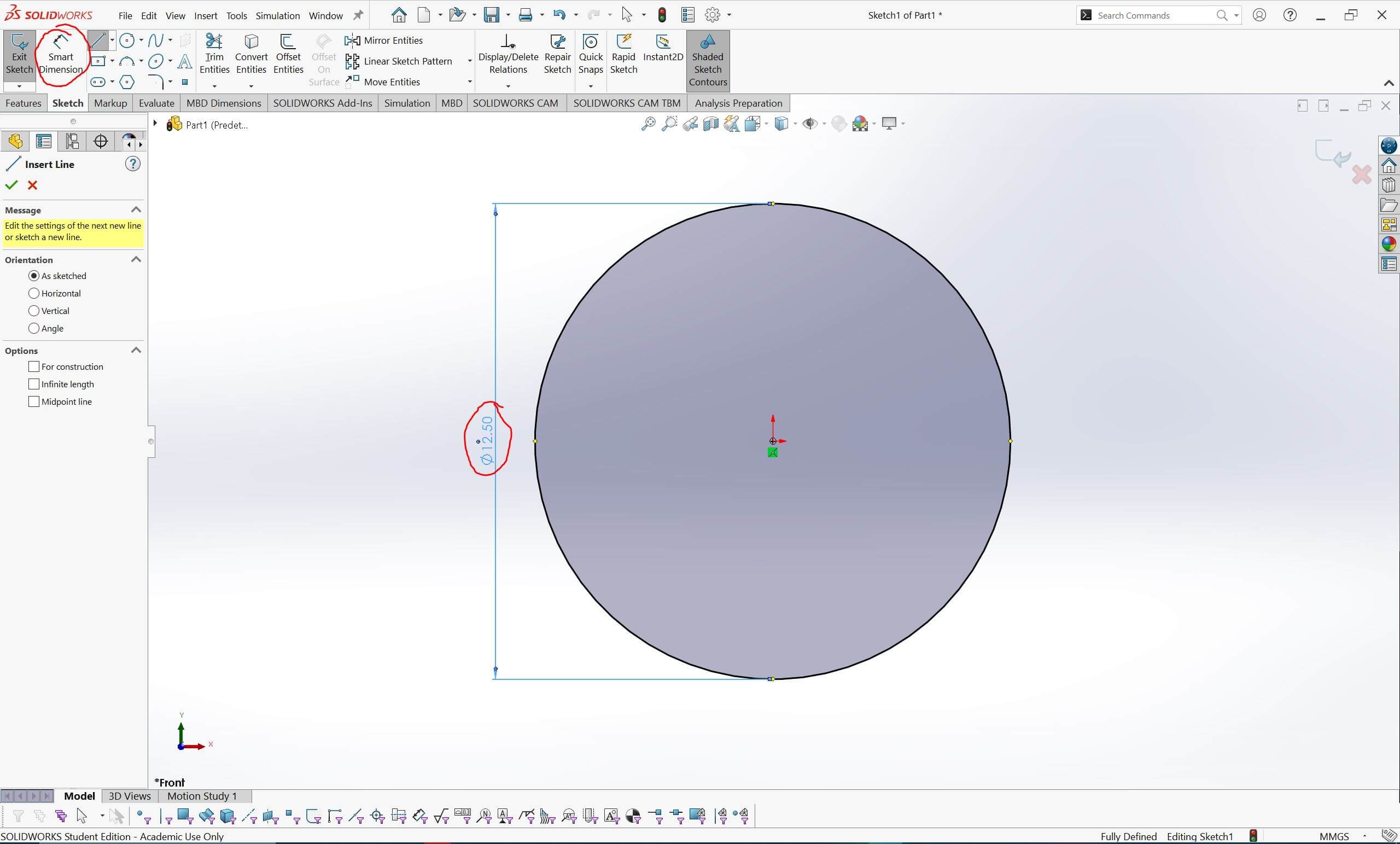
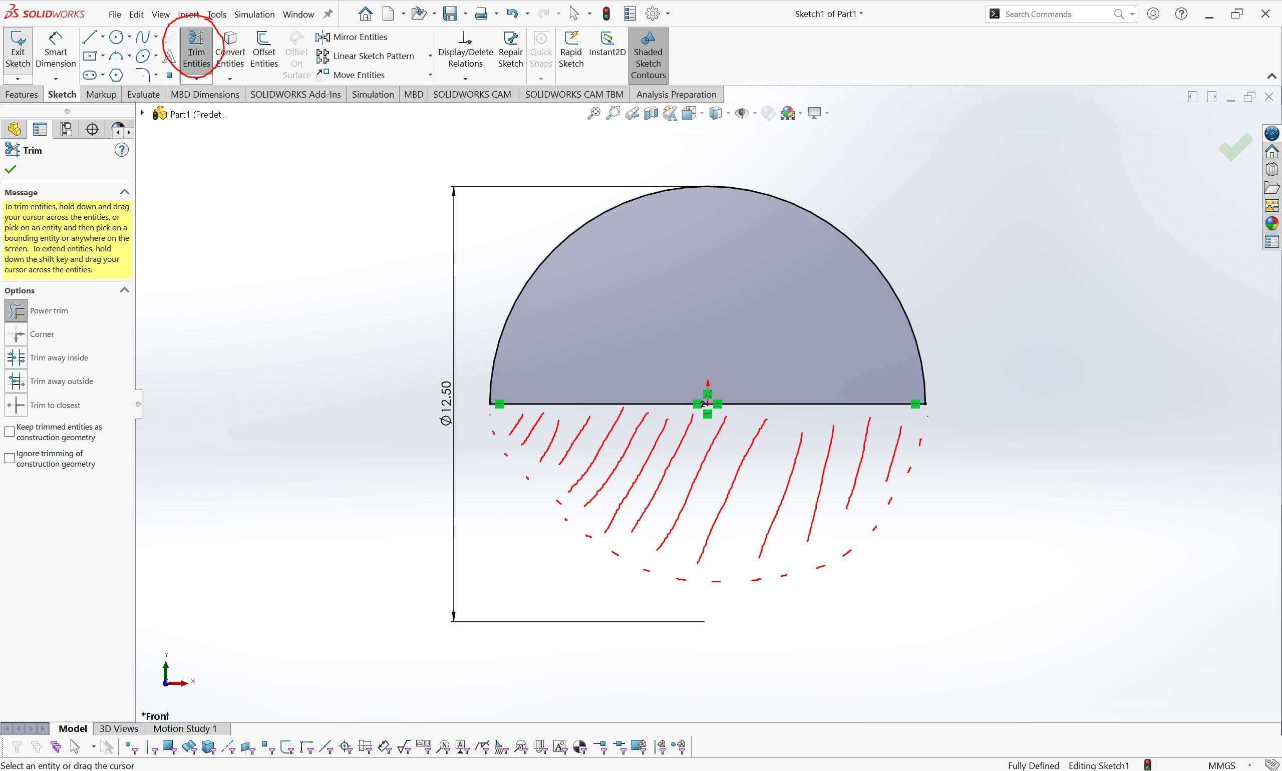
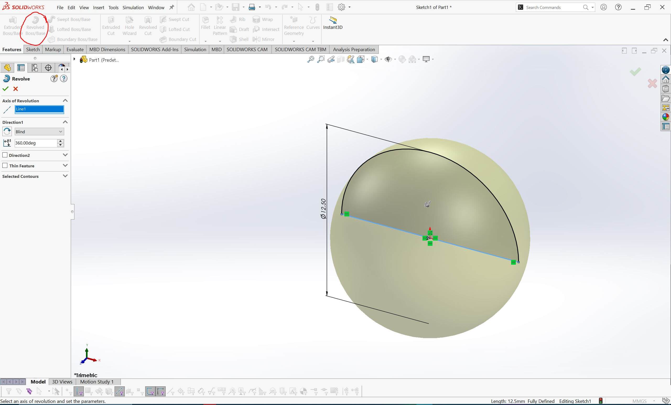
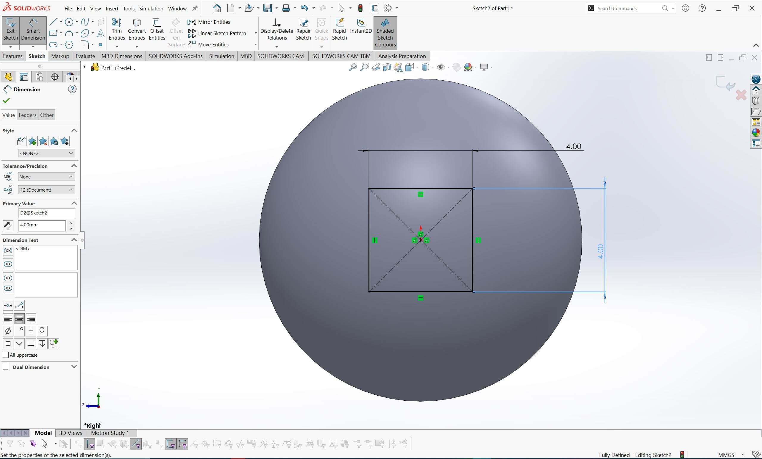
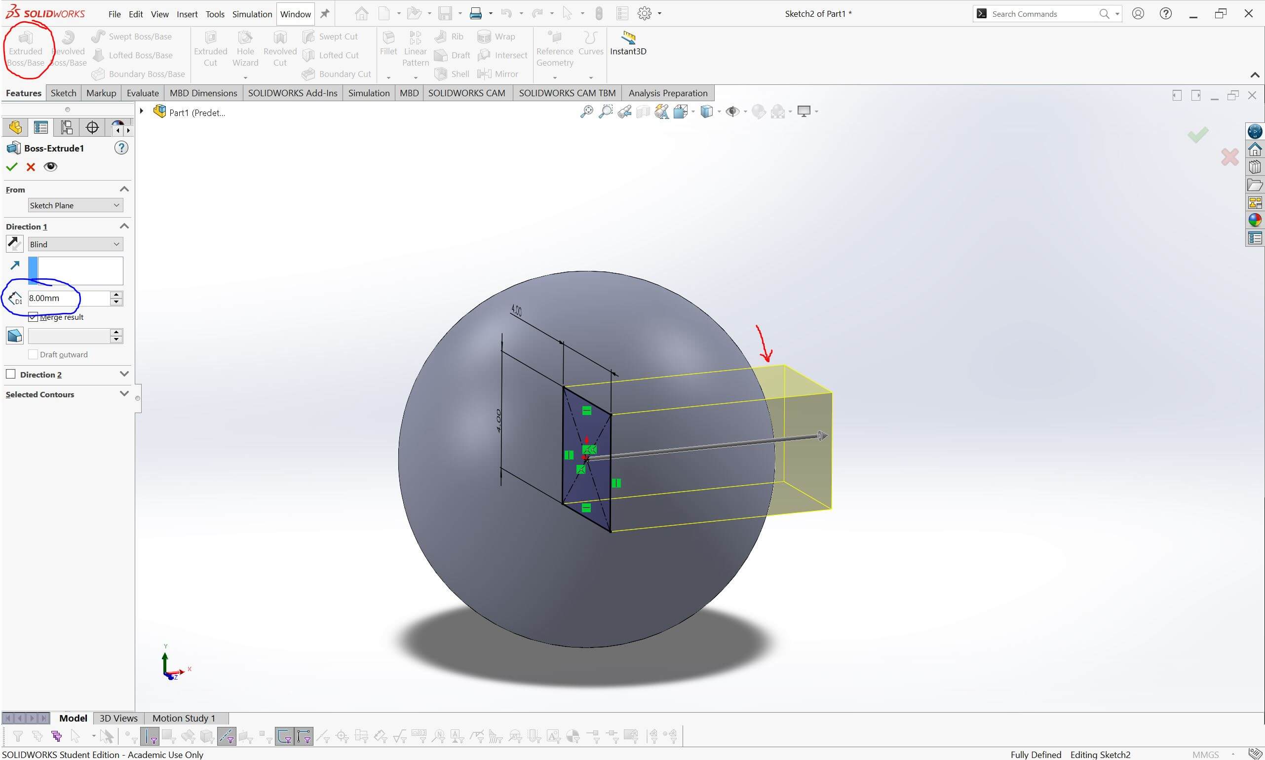
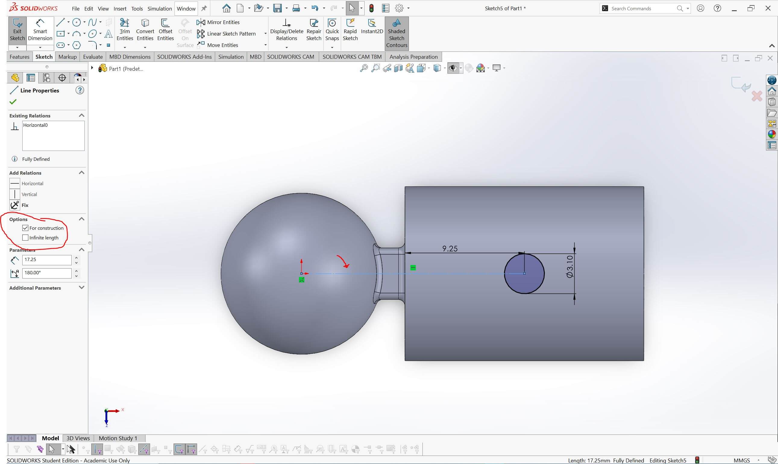
With the sphere already created, we will now design the extension that connects it to the aluminum tubular support. Since the sphere was made at the center, there is no need to create a new plane. Instead, we can extrude the extension from within the sphere so that it extends outward.
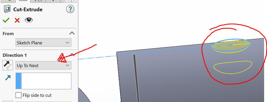
Once the extension is complete, we will create the aluminum tubular support. To do this, we will use the flat face of the extension to create a new sketch (since the software recognizes it as a flat surface). The support will be designed considering that the aluminum tubular has a thickness of 10 mm, with tolerances already accounted for in the design.
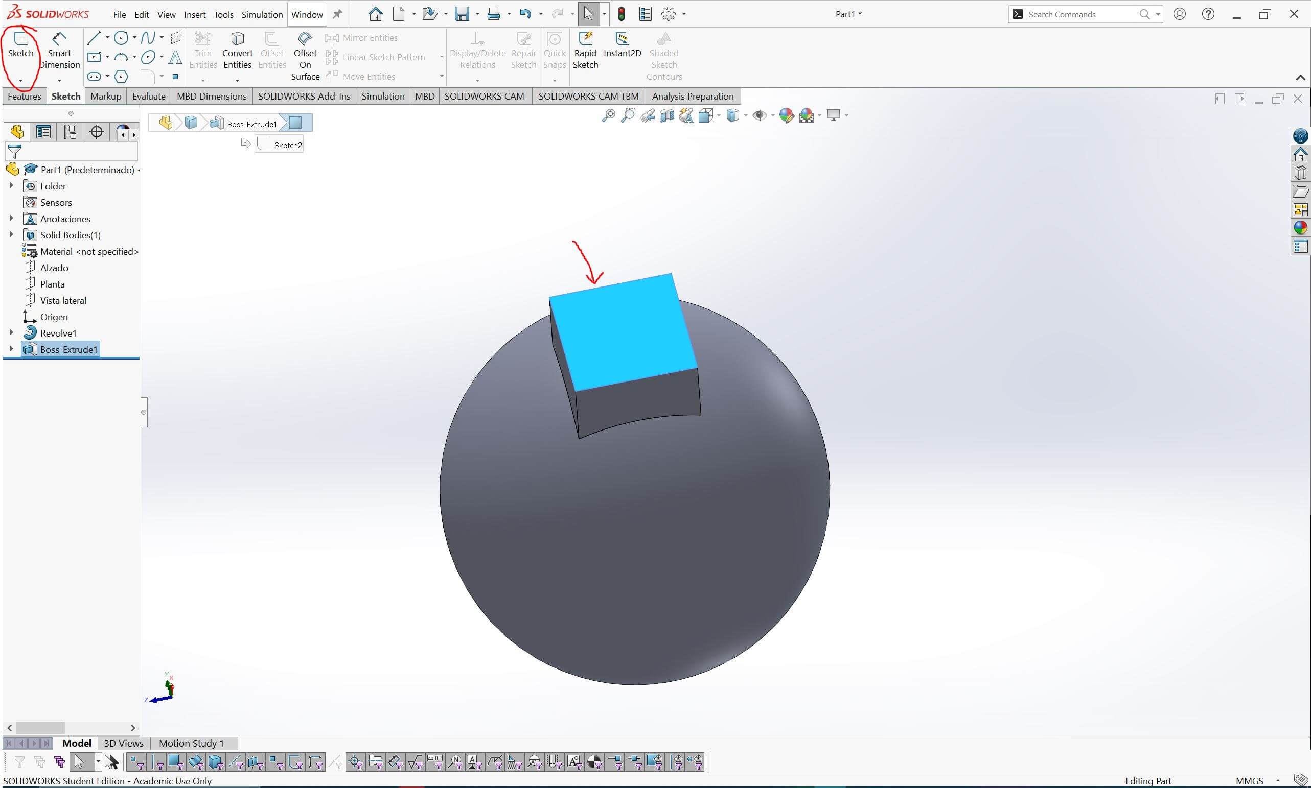
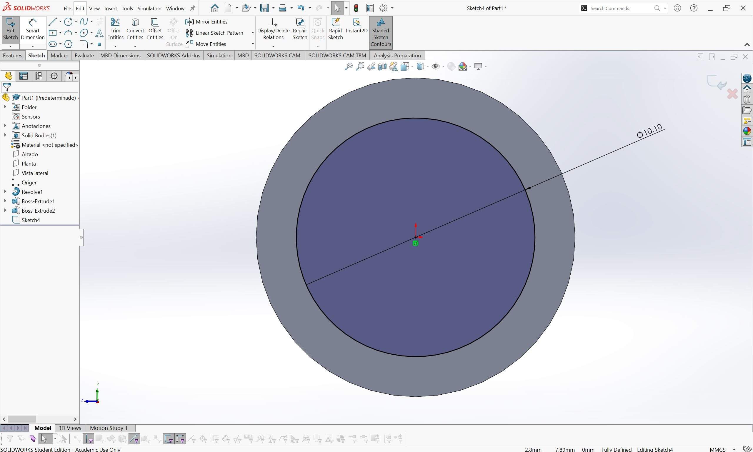
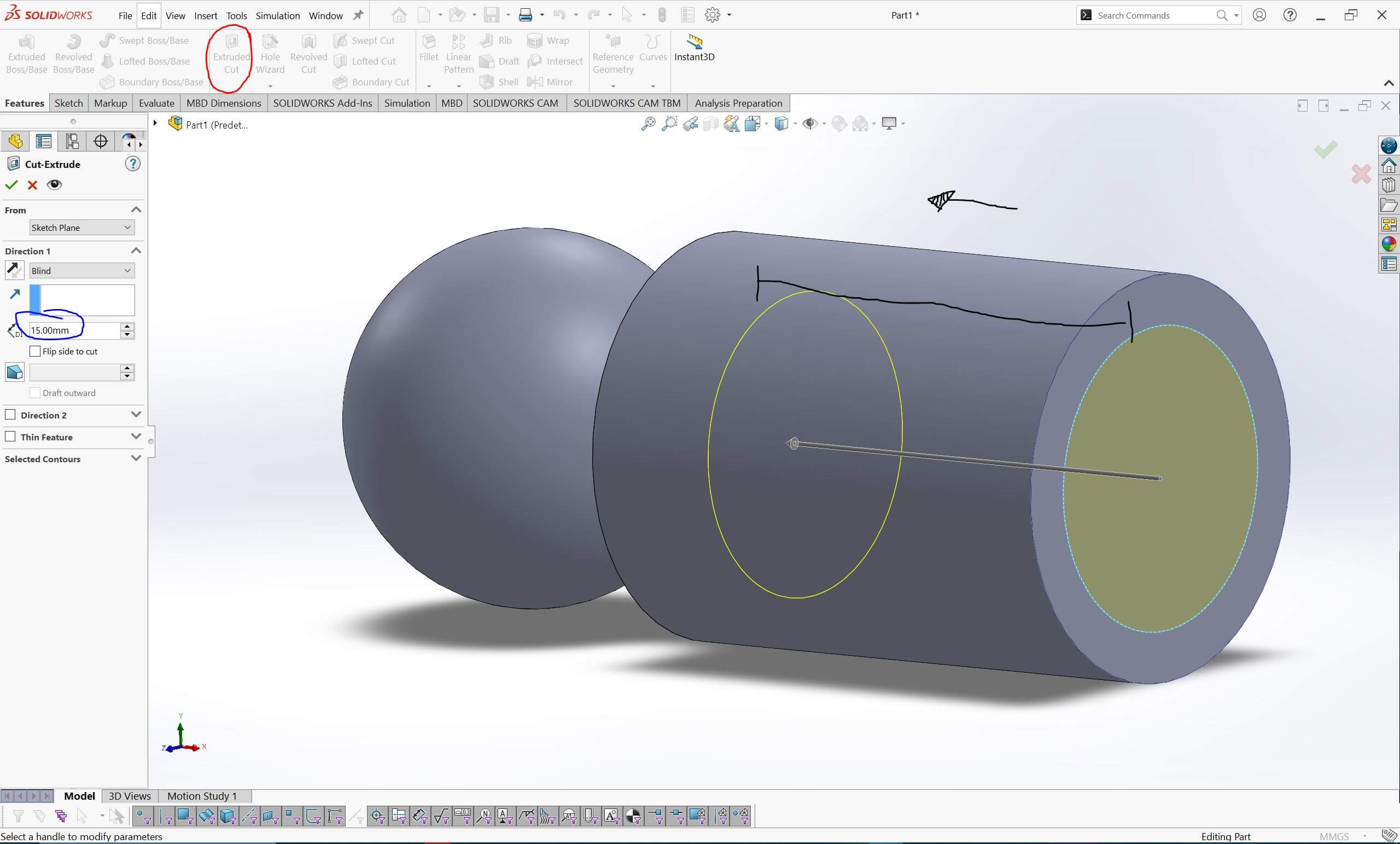
Figure 14: Extrude cut of the tubular diameter.
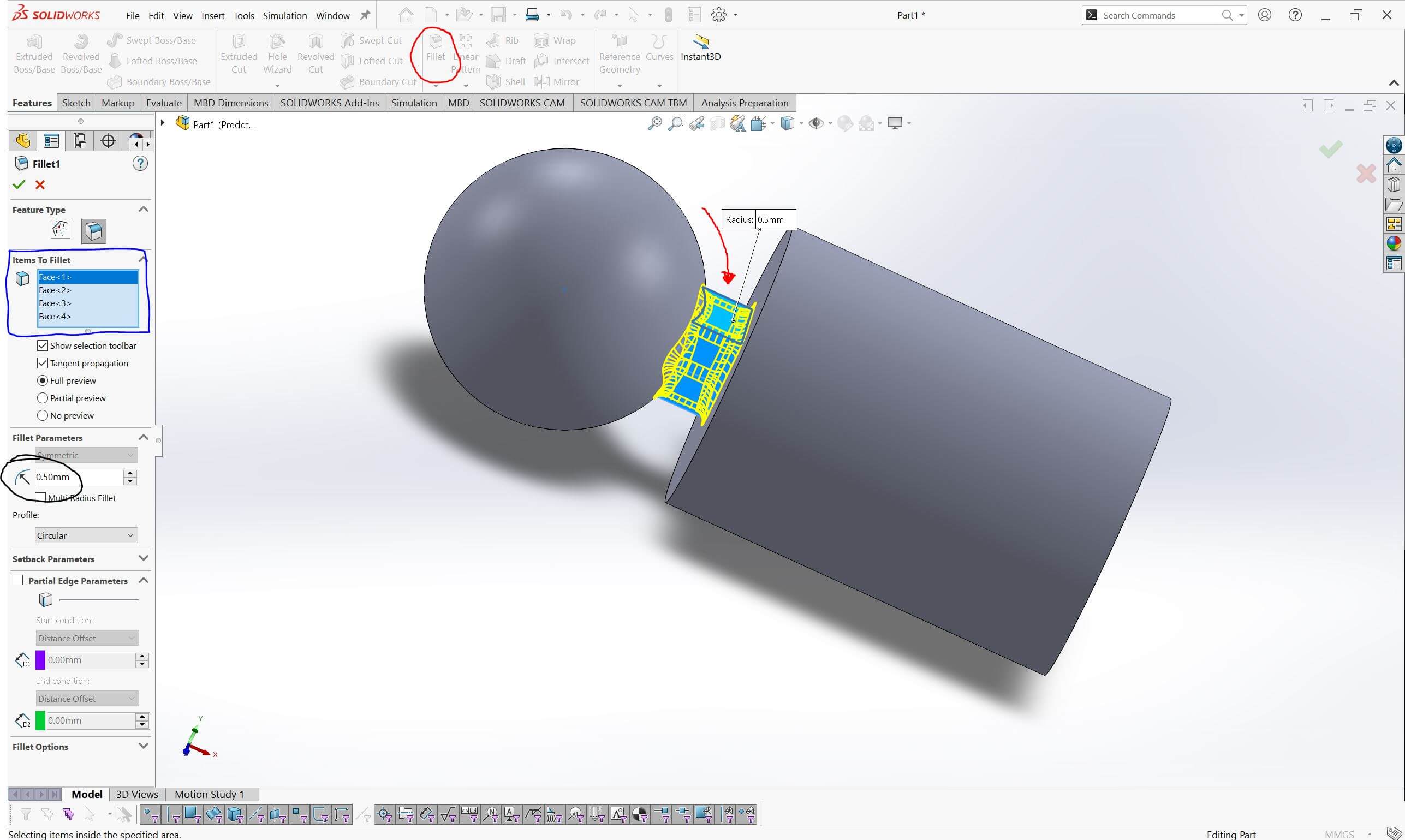
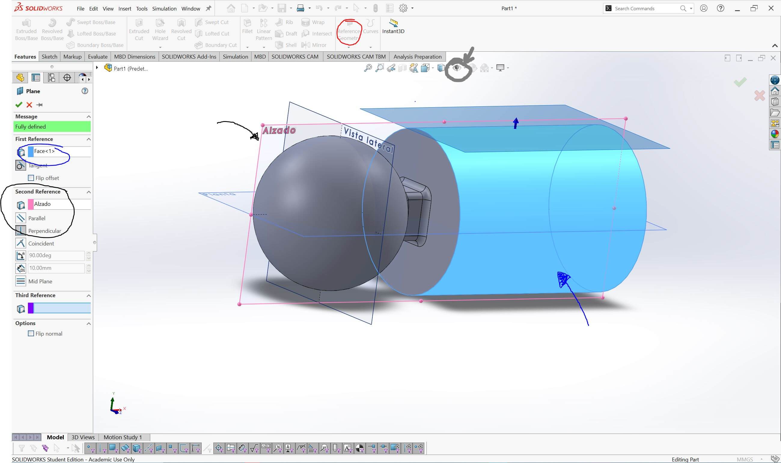
Technically, we could leave the design as it is since it fulfills its function. However, because this part will be subjected to stress, we will increase the contact points between its sections using the Fillet tool. Additionally, we will create a hole for a grub screw to securely hold the aluminum tubular in place.
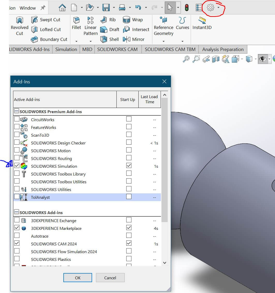
Static analysis in Solidworks
Now that the piece is complete, will it hold up? As mentioned earlier, this part will be subjected to stress since it serves as a connector. This means there is a possibility it could fail under load. To evaluate its structural integrity, we will simulate a real-case scenario, assuming the sphere remains fixed while supporting the weight of the support cylinder, the tubular, and possibly other forces.
For this simulation, I will assume that both the weight of the tubular and external forces create a distributed force of 10 kgf throughout the cylinder. This value is exaggerated, considering that the tubulars are hollow, do not span long distances, and that the forces affecting the joint are distributed across the rest of the animatronic’s structure.
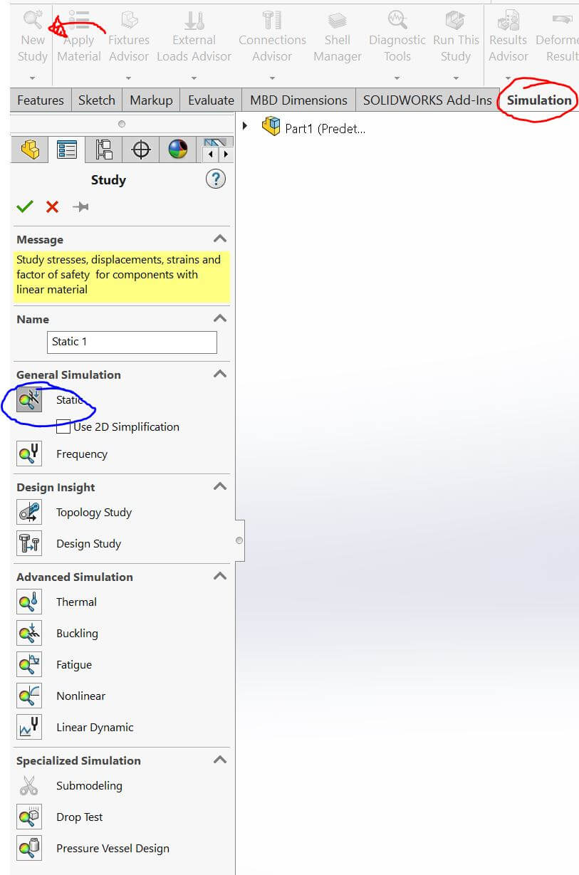
The part is designed to be 3D printed using PETG. However, obtaining accurate material properties for simulation can be challenging due to the nature of PETG. Therefore, for the analysis, I will use the mechanical properties of ABS, as it shares similar strength and flexibility characteristics with PETG.
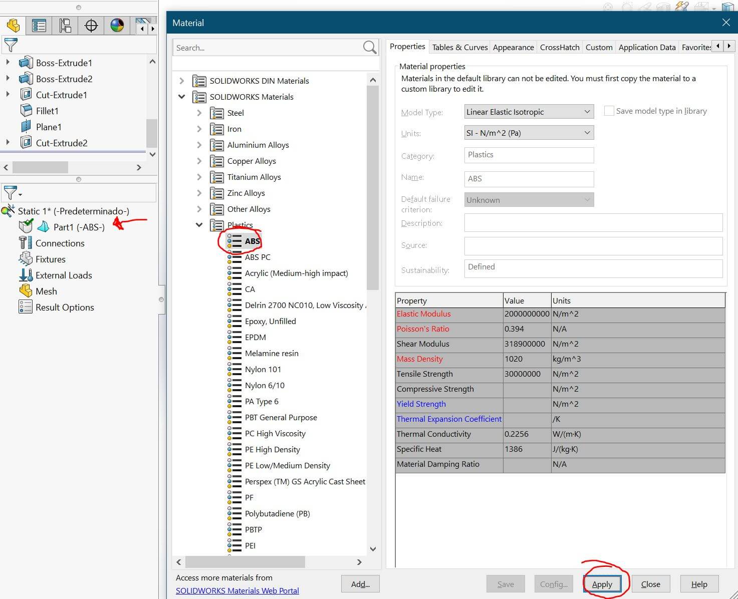

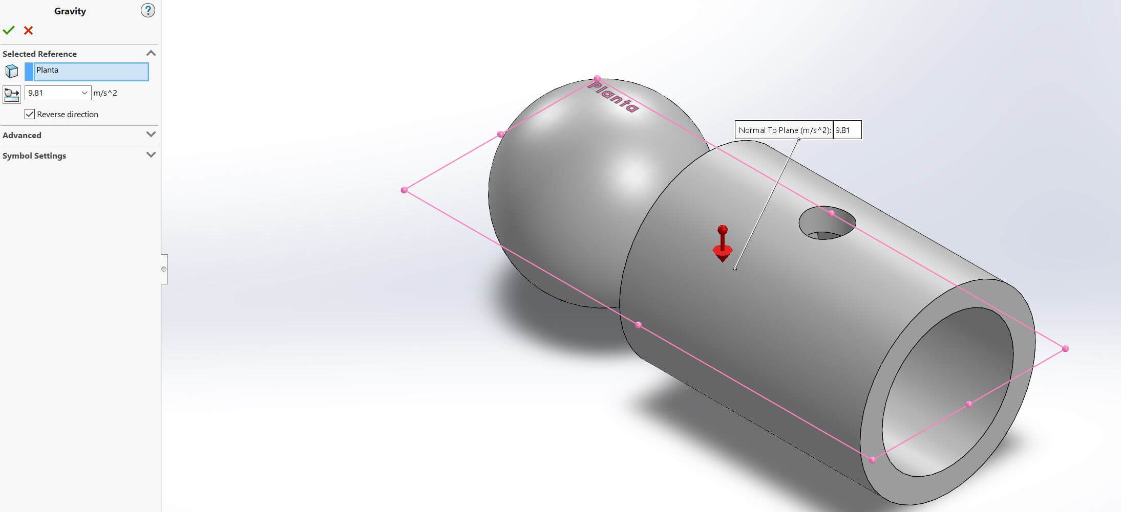
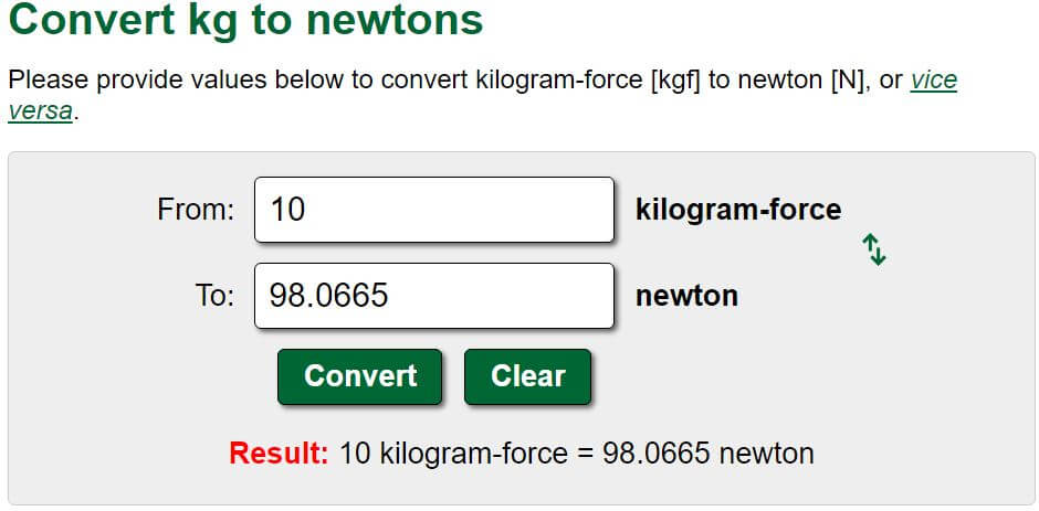
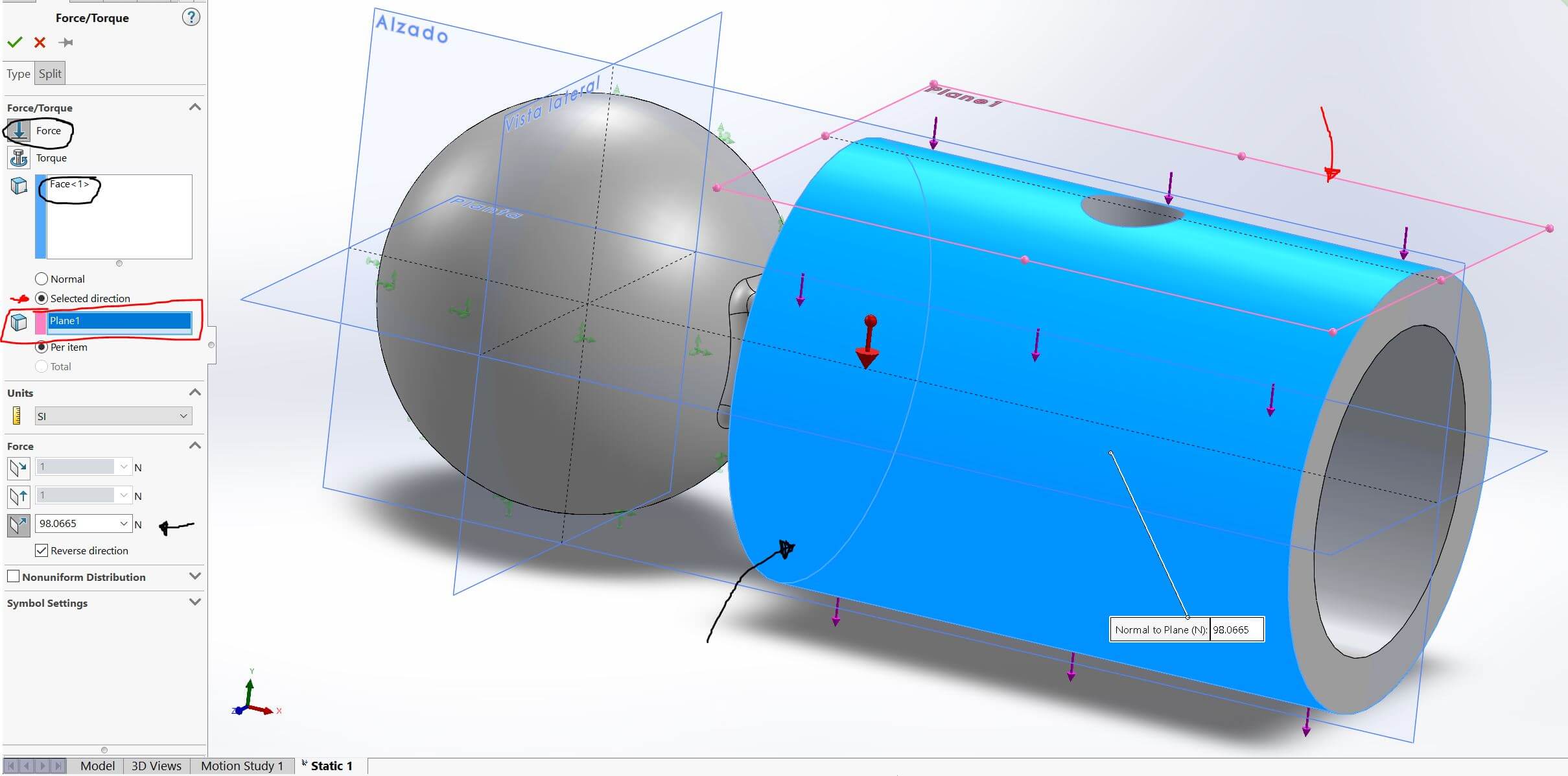
Figure 25: From "external loads", consideration of the rest of the forces.
Once all the points to be considered for the analysis have been entered, we begin the simulation.
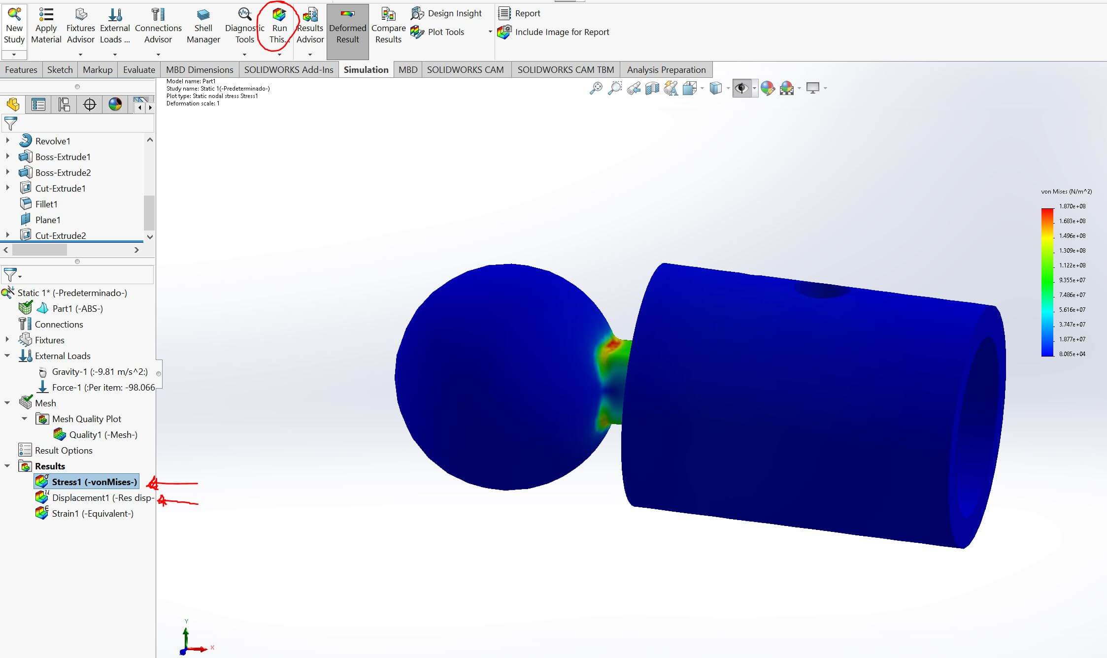
Figure 25: Run simulation.
Once the process is complete, the analysis menu where we entered the data will display two new options showing the simulation results. One will be the stress analysis, which highlights critical points, and the other will be the deformation analysis, which helps determine whether the part will break or withstand the applied forces.
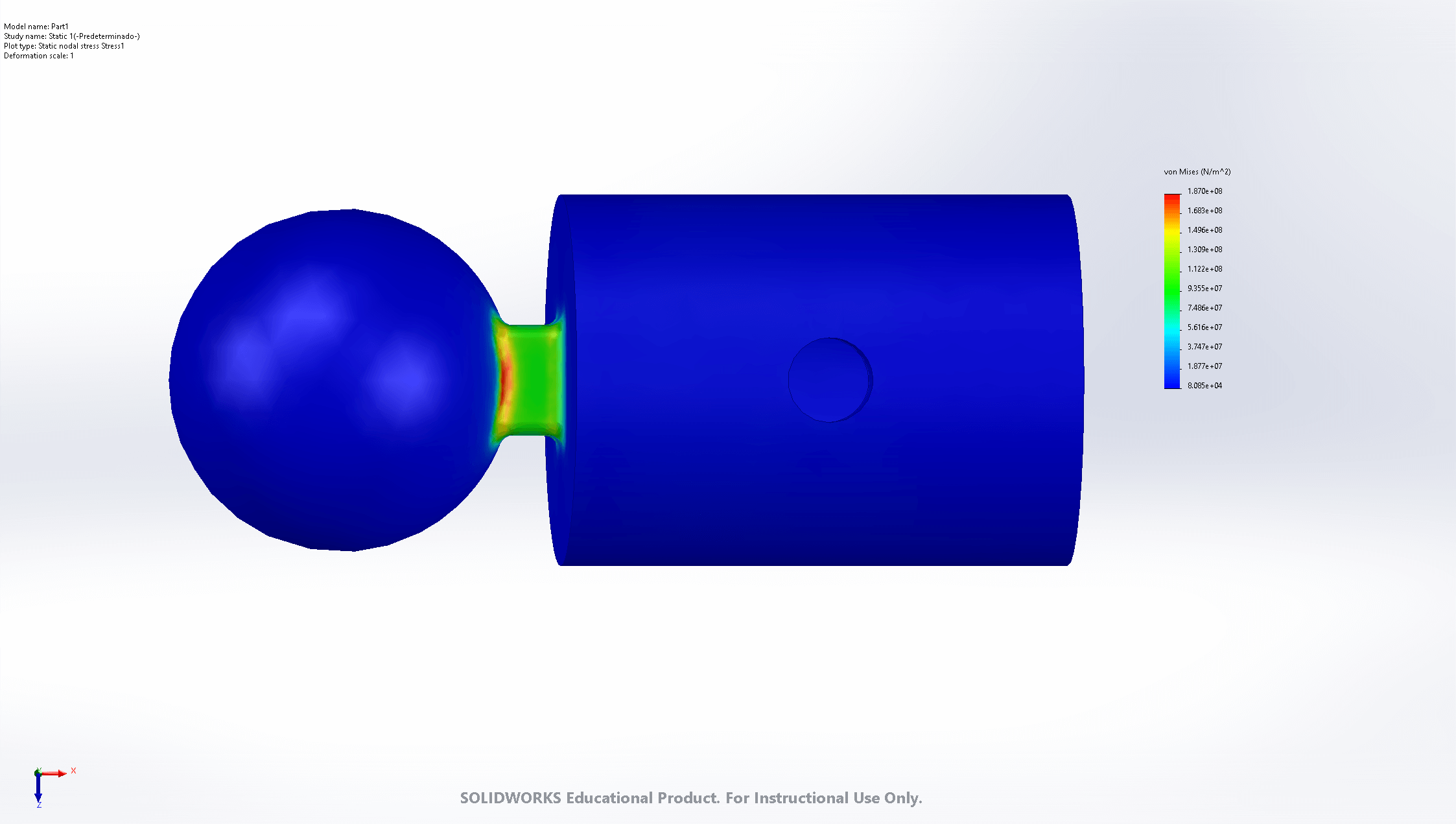
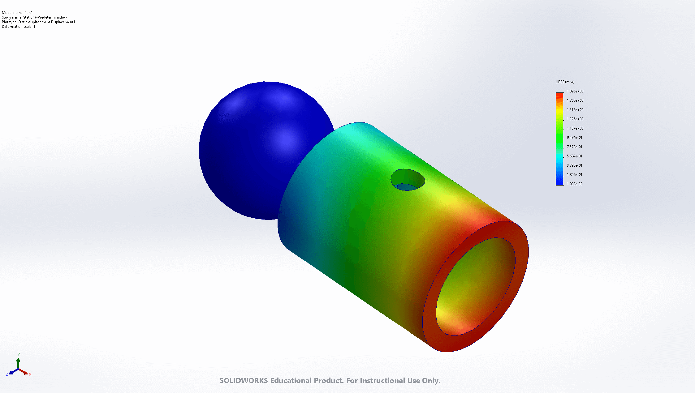
According to the obtained data, the external forces applied to the cylinder supporting the aluminum tubular were indeed exaggerated. The deformation observed is significant for the mechanical properties of PETG or ABS. However, even under these conditions, the part could likely withstand a slightly lower force, around 8 kgf, which is more than sufficient for our application.
FUSION 360
In Fusion 360, as previously mentioned, we are working on the design of a universal node, which will serve as the connection point for the joints previously created in SolidWorks.
Regarding the software, Fusion 360 operates similarly to SolidWorks, but many of its tools are hidden in drop-down menus. However, the most essential tools remain visible. Additionally, editing menus appear on the right side of the interface, while a timeline of operations is displayed at the bottom, allowing us to track and modify design steps efficiently.
Concerning the piece, the key aspect to consider is that it serves as a node for the joints. Therefore, the design focuses on keeping it as compact as possible. Additionally, for assembly, the universal joint and the universal node will be connected using a fastener piece, which will be screwed onto both components to apply enough pressure and keep them securely in place.
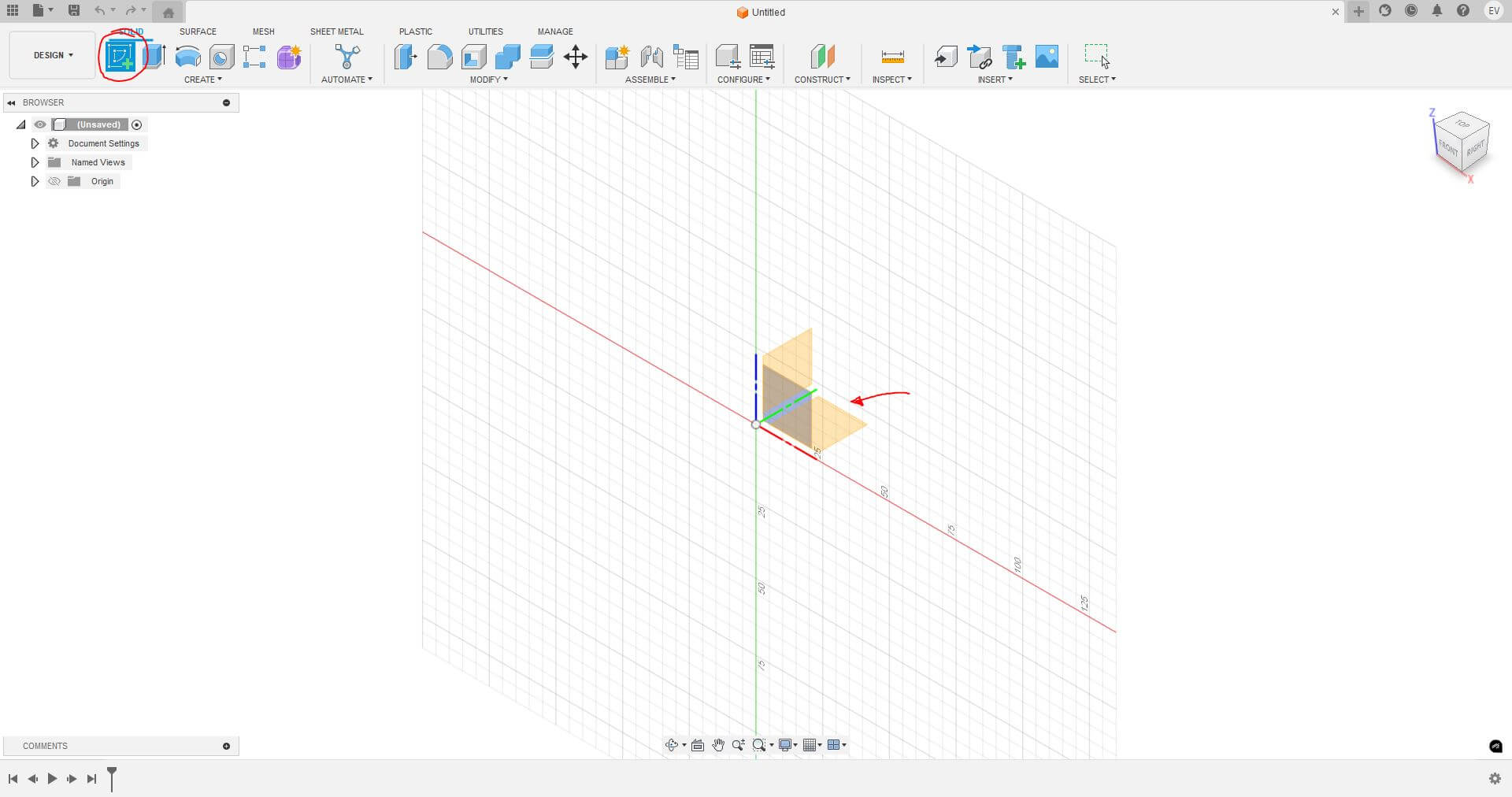
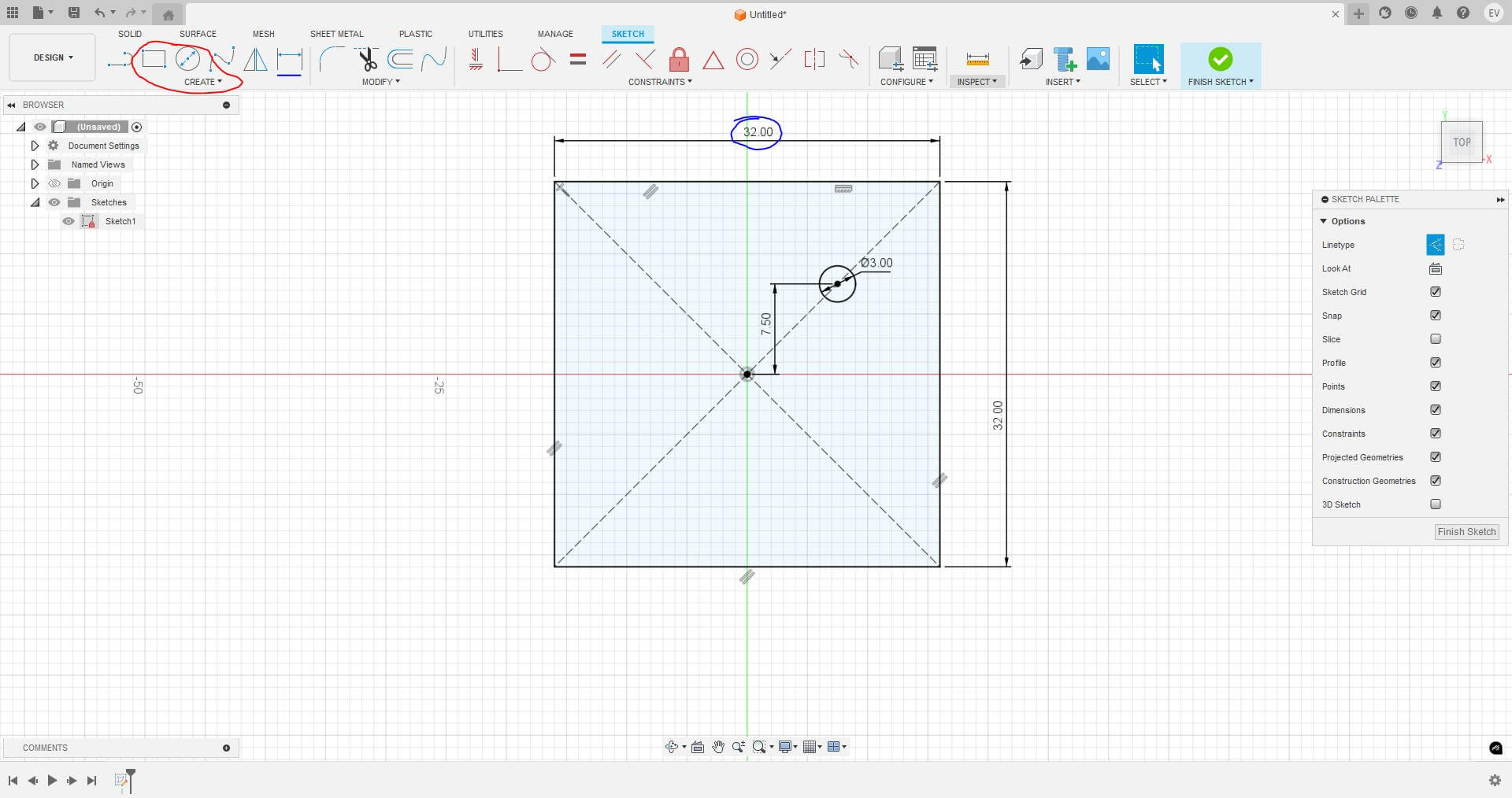
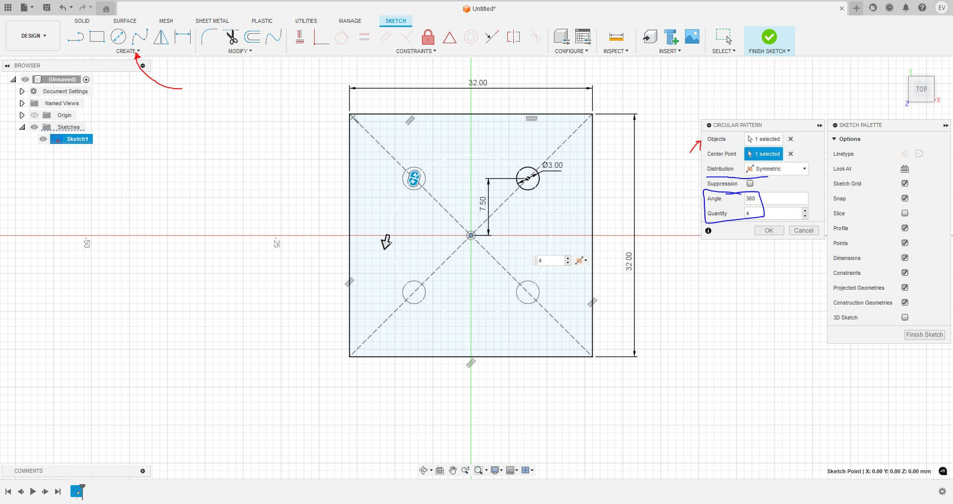
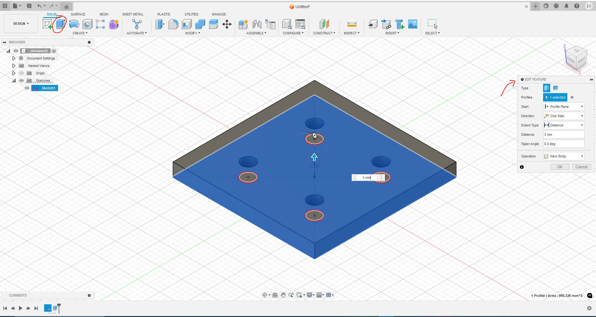
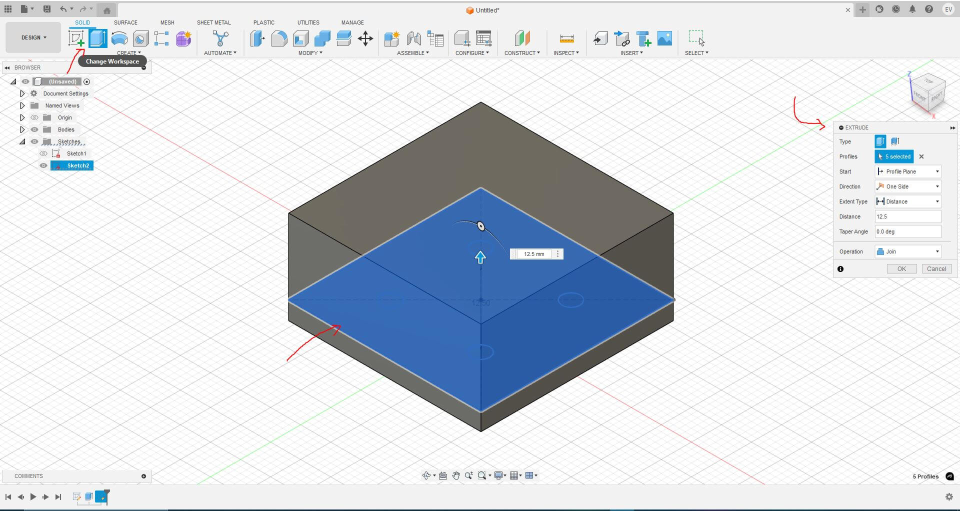
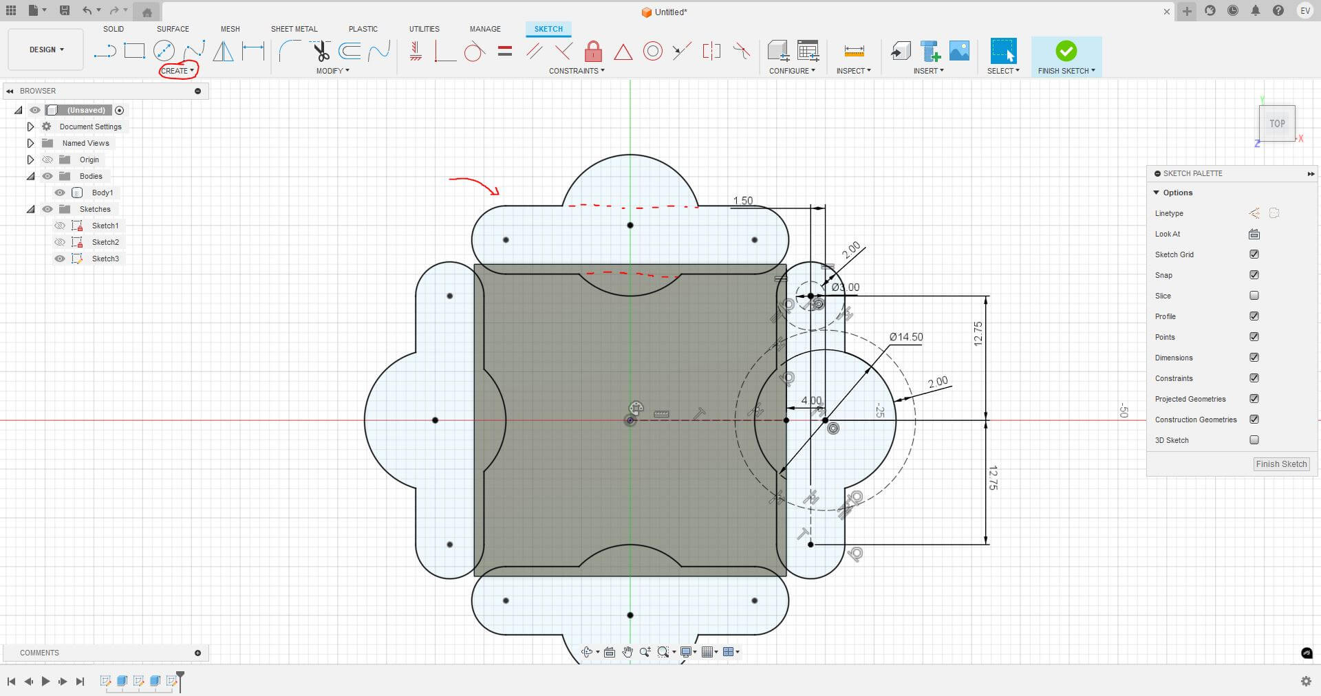
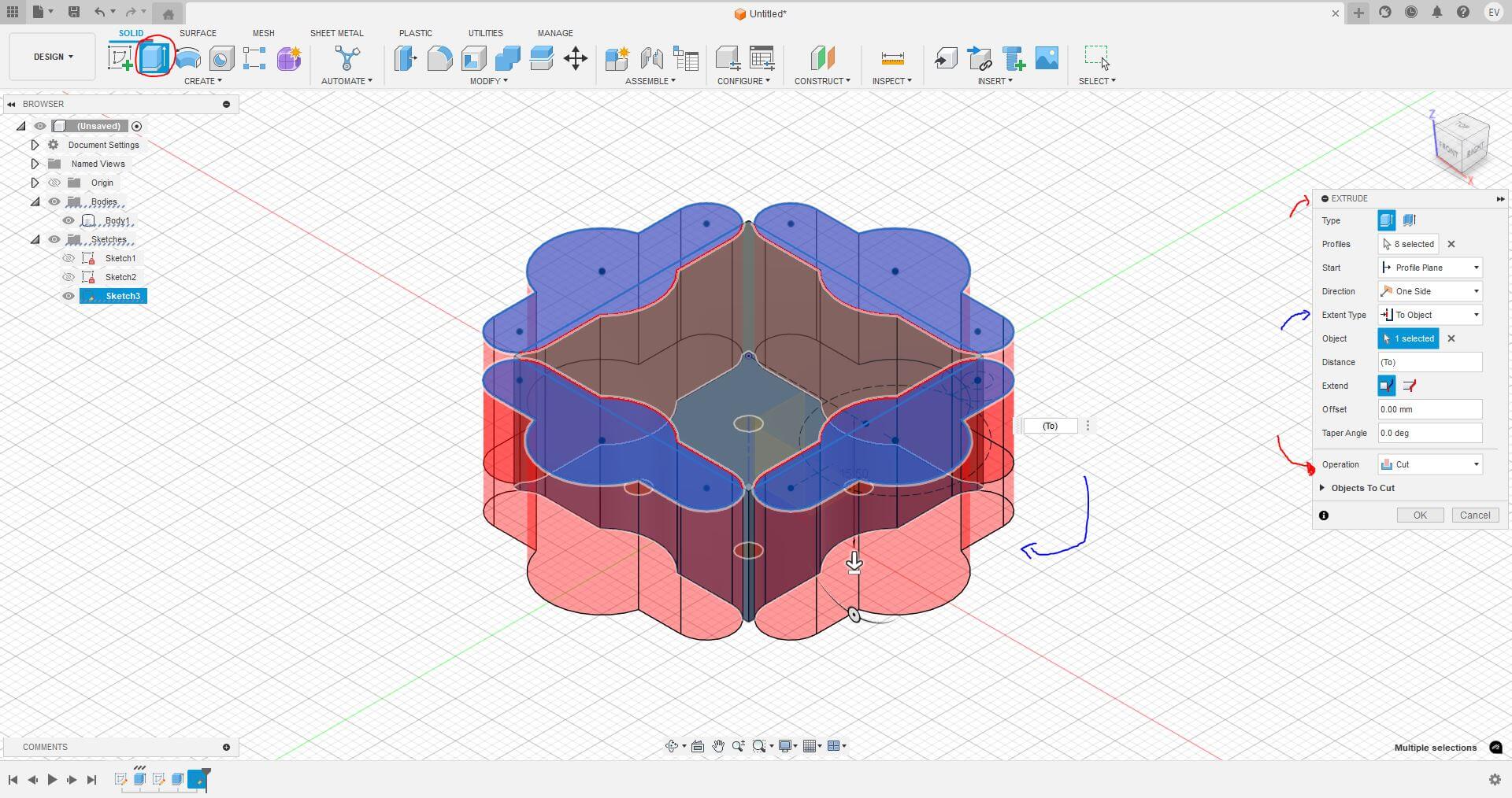
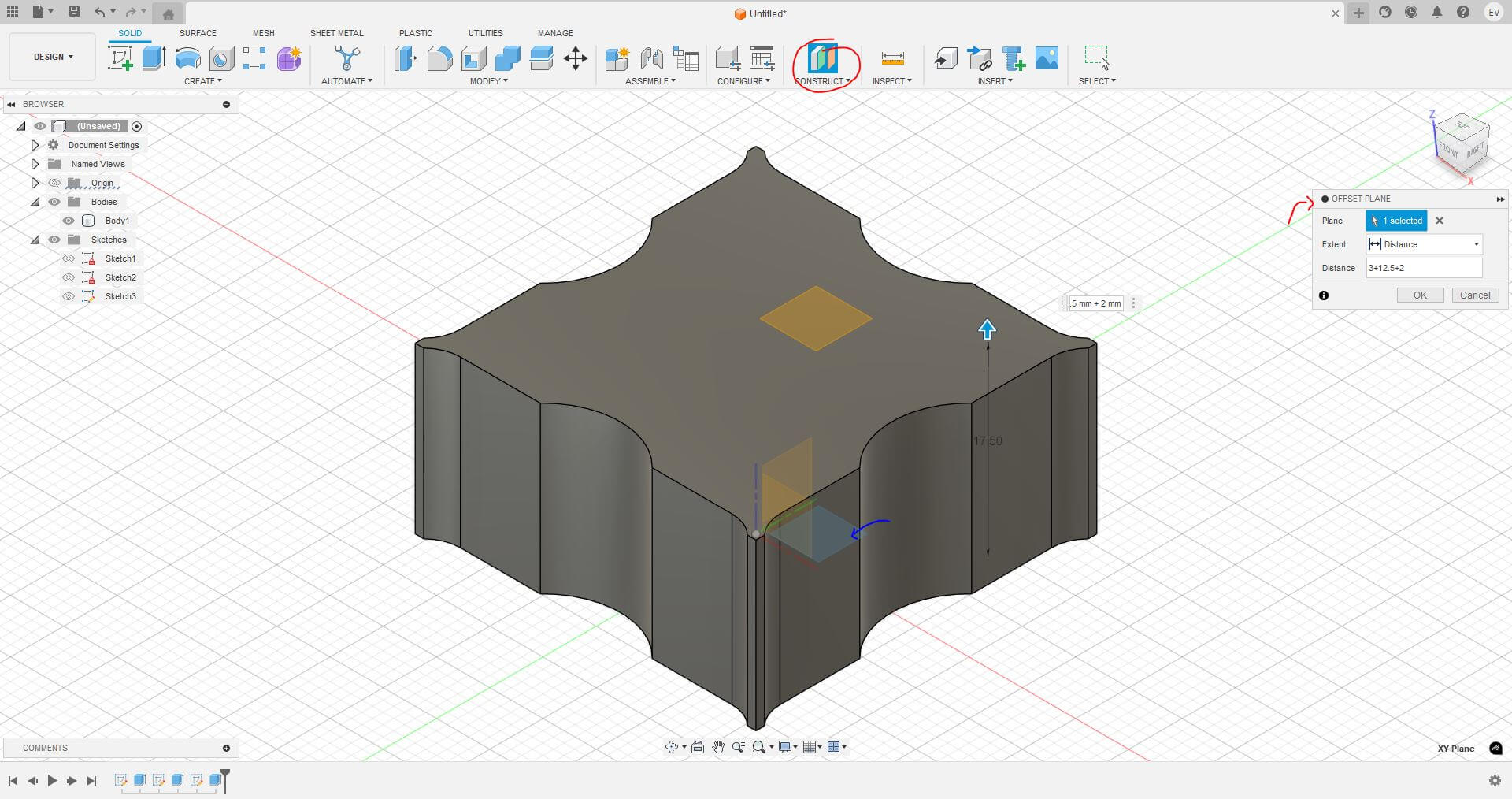
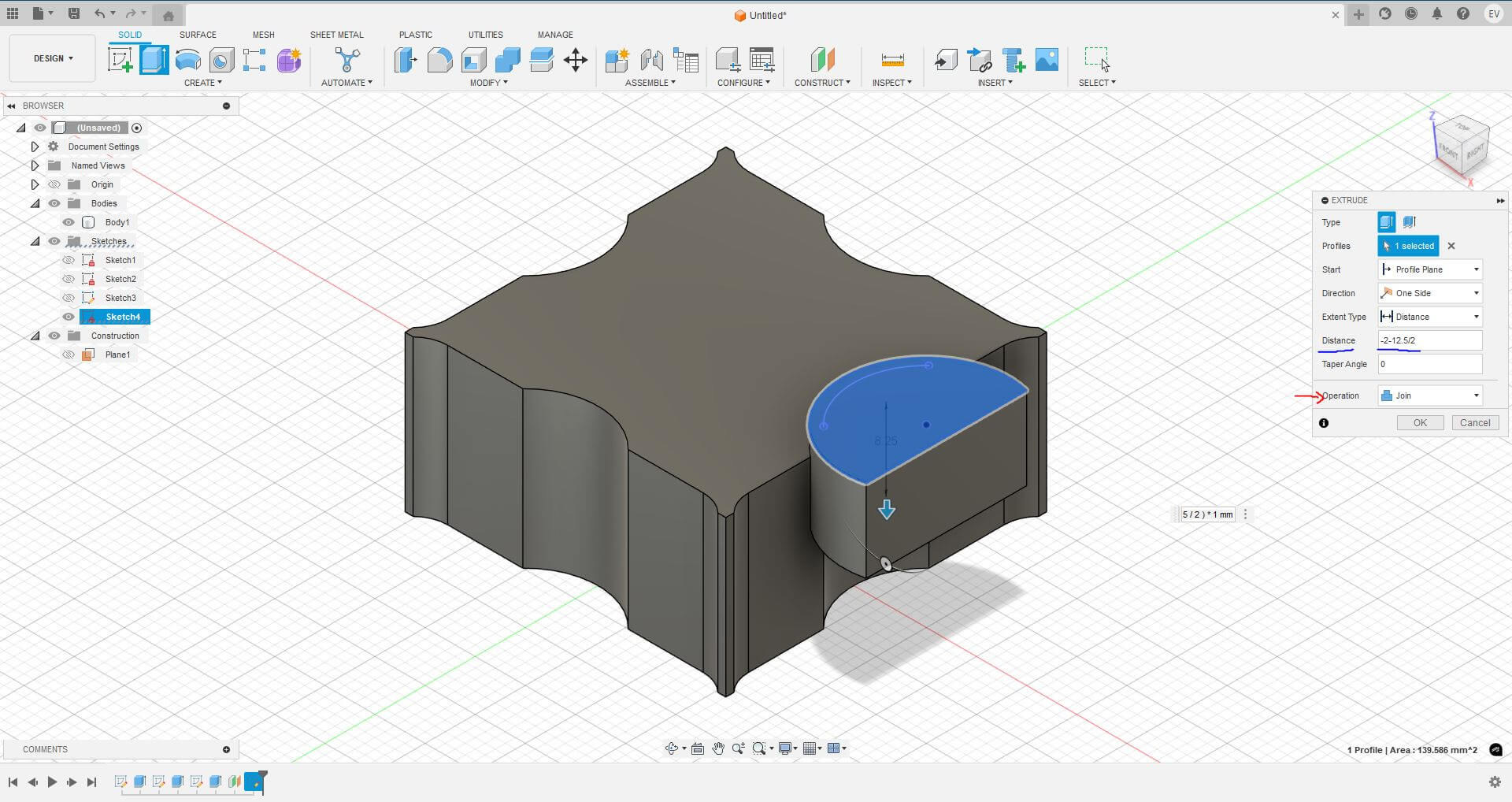
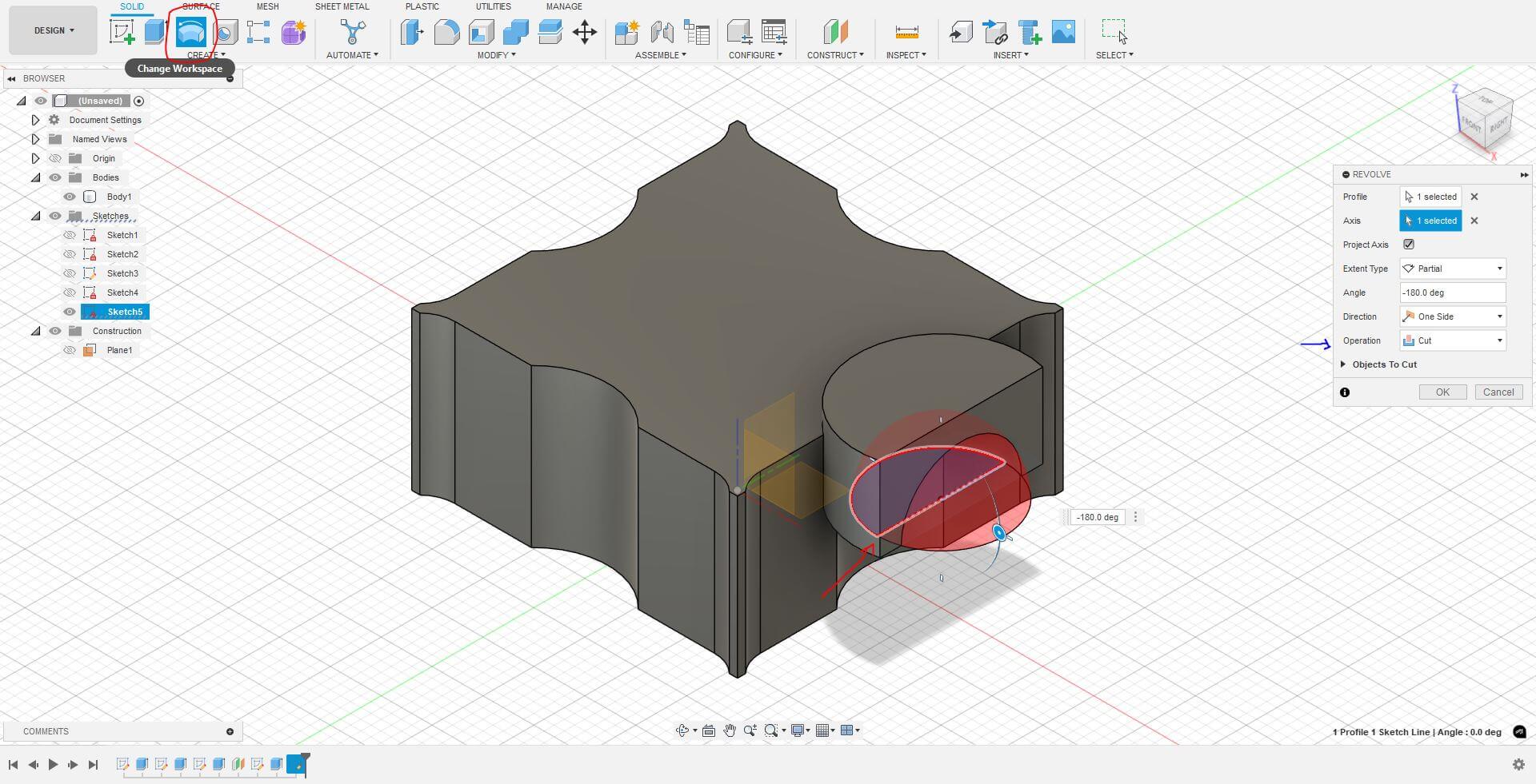
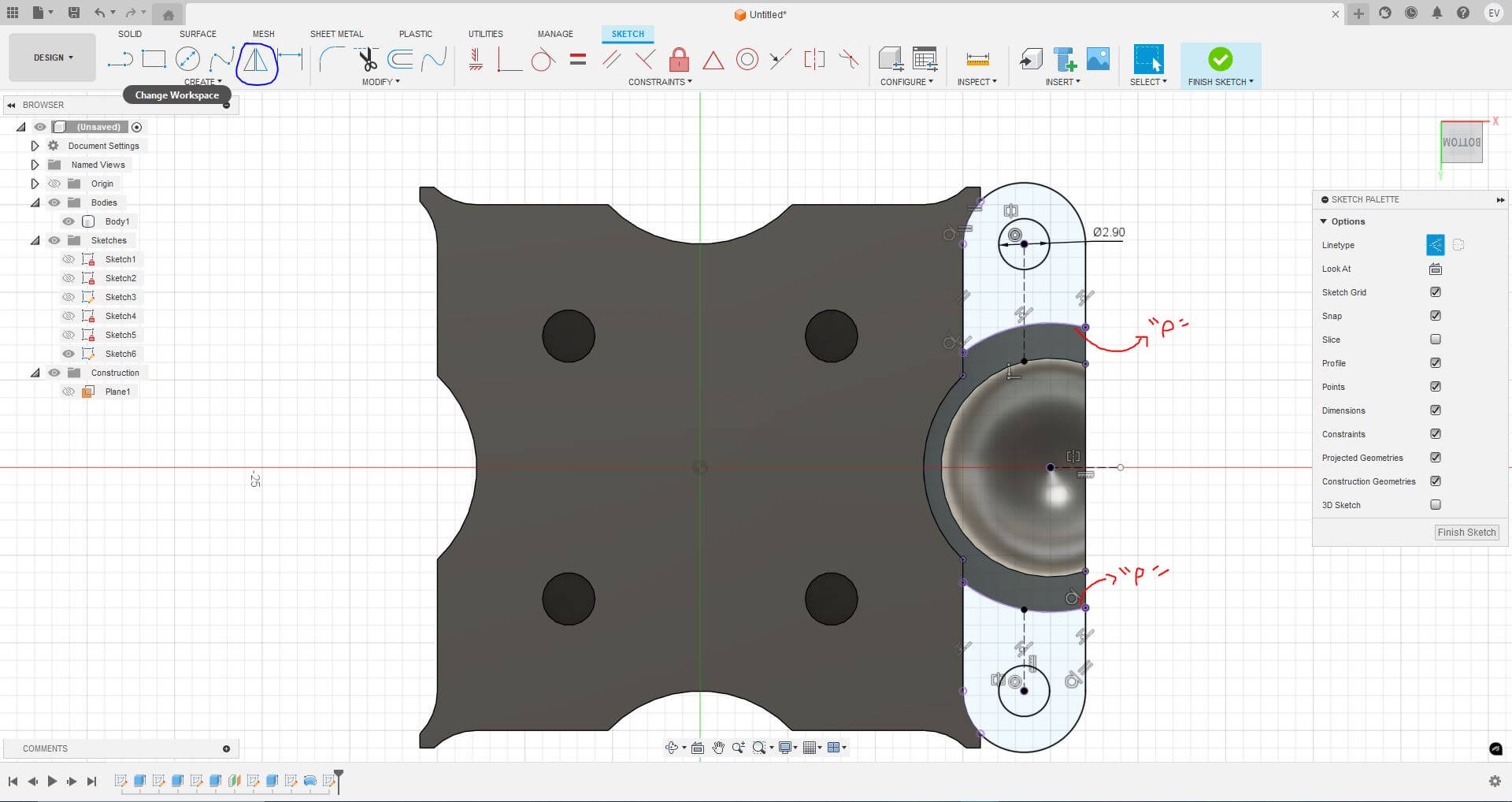
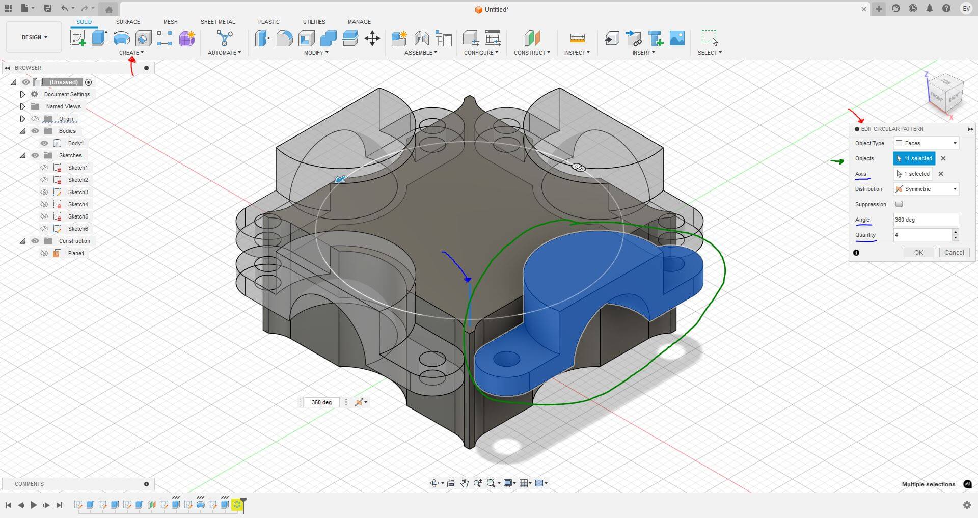
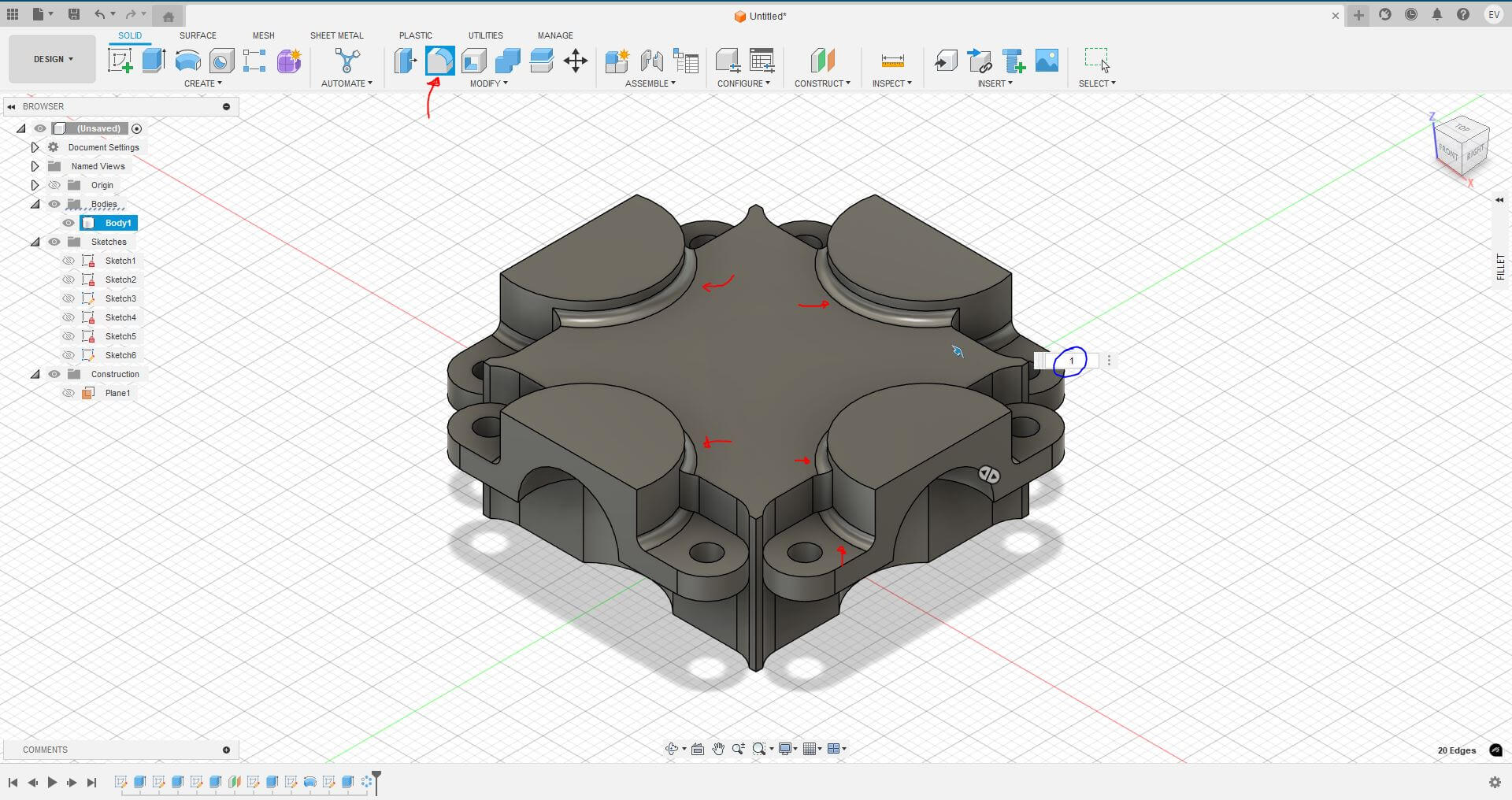
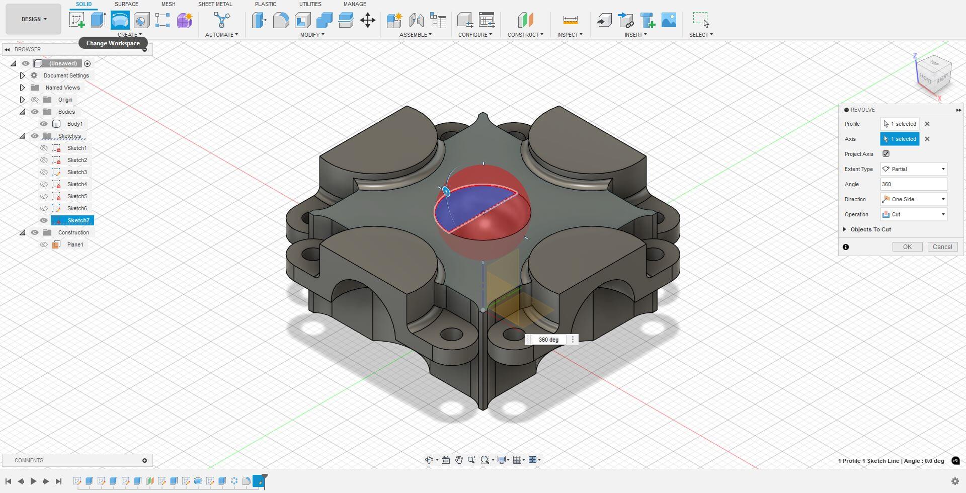
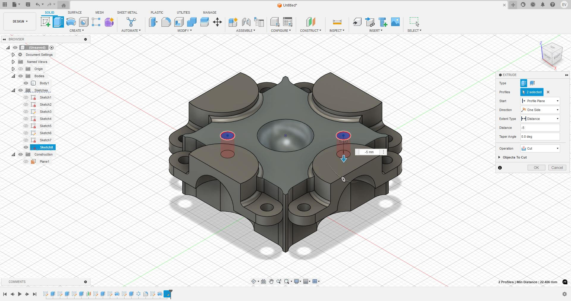
Figure 42: Holes to fix the upper union.
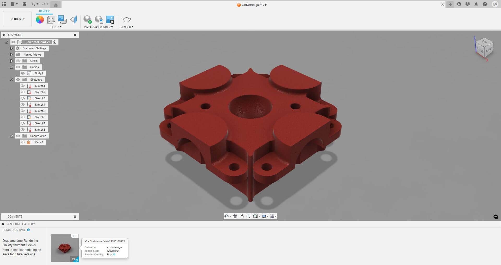
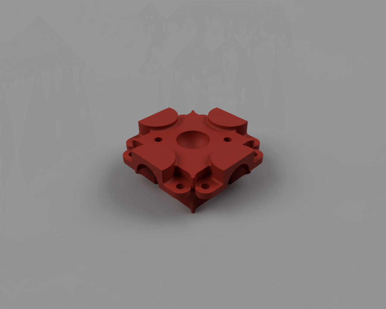
This is the first version of the universal node. It may undergo modifications or adaptations later. For now, I will demonstrate how to render the model to enhance its definition and detail in an image.
In my opinion, rendering has always been a bit tedious, whether in CATIA or SolidWorks. However, in Fusion 360, the process is incredibly easy!. Simply entering the rendering menu allows the interface to guide you through the process, even providing an estimate of the final file size based on the selected specifications and options at the time of rendering.
To render in Fusion 360, simply explore the tools available in the "SETUP" section of the top menu. Once everything is configured, just hit render, and the process is complete.
TINYPNG
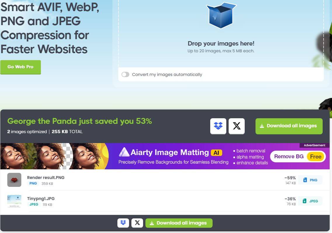
As you can see on the page, I have already uploaded more than 40 images! At this point, I would have definitely reached the upload limit. However, thanks to TinyPNG (an online tool), I was able to compress the images without significantly losing quality.

LEARNINGS
In summary, this week, in addition to improving my proficiency with well-known software tools such as SolidWorks, I also gained experience using Inkscape and Fusion 360, at least for my specific needs. Mastering CAD software like SolidWorks, Fusion 360, and Inkscape enhances control over prototyping and manufacturing, making the design process more efficient and precise.
