Interface and Application Programming
In many embedded system projects, it's necessary to establish a reliable and intuitive way for users to interact with the hardware. While command-line tools and serial terminals offer basic communication, they are rarely suitable for end users or for practical deployment. This is where user interfaces become essential: they serve as the communication bridge between the human operator and the system's internal logic.
A user interface (UI) can take many forms, from simple physical buttons and displays to complex graphical applications or web-based dashboards. The goal is to facilitate control and monitoring in a way that is both effective and user-friendly. A well-designed interface not only improves usability, but also enhances data interpretation and system reliability through visual or interactive feedback.
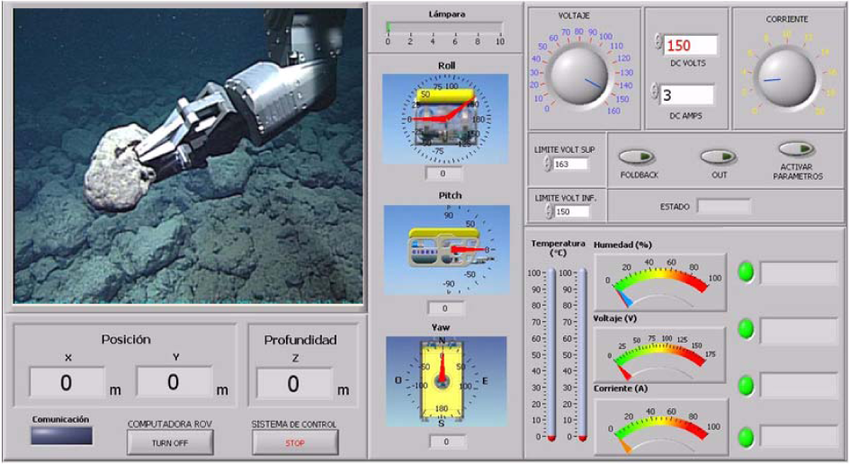
Figure 1: Graphical User Interface Example.
Types of Interfaces
Interfaces can be broadly categorized based on how interaction is achieved. Each type has advantages and limitations, and their suitability depends on the system's complexity, required feedback, and context of use. Below is a comparative summary:
| Type | Description | Advantages | Limitations |
|---|---|---|---|
| Physical Interfaces | Include push buttons, rotary encoders, knobs, or touchpads directly wired to a microcontroller. | Immediate response, simple implementation, does not require software drivers. | Low scalability, limited to basic interaction. |
| Command-Line Interfaces (CLI) | Interaction is performed through textual commands via a serial monitor or terminal. | Precise control, efficient for debugging and development. | Not user-friendly, no graphical feedback. |
| Graphical User Interfaces (GUI) | Desktop applications with buttons, sliders, input fields, etc. | High flexibility, intuitive control, supports real-time feedback. | Requires software libraries and more processing resources. |
| Web Interfaces | Built using HTML, CSS, and JavaScript, hosted locally or remotely. | Cross-platform access, remote control capability. | Requires networking knowledge, setup is more complex. |
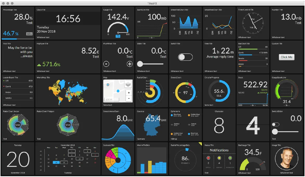
Figure 2: Mqtt interface example.
Frameworks for Interface Development
Several programming frameworks exist to build user interfaces, each with different features and ideal use cases. The choice depends on the hardware platform, the communication protocol, and the complexity of interaction needed.
| Framework | Language | Best Use Case | Remarks |
|---|---|---|---|
| PyQt / PySide | Python | Desktop GUI apps for local control and visualization | Extensive documentation, supports complex layouts and signals/slots |
| MQTT | Any (Python, C++, etc.) | Publish/subscribe messaging between devices, ideal for IoT | Lightweight protocol, requires a broker (e.g., Mosquitto, EMQX) |
| Tkinter | Python | Simple GUIs with minimal dependencies | Included in Python standard library, limited aesthetics |
| Flask / Django + JS | Python + HTML/CSS/JS | Web-based dashboards and control panels | Supports REST APIs, asynchronous updates with JavaScript |
For more info, here is our group assignment.
Why PyQt Was Selected
For this particular project, PyQt was chosen due to its robust support for graphical user interfaces and its seamless integration with Python. PyQt is a set of Python bindings for the Qt toolkit, which is known for its stability and flexibility across platforms (and also because it's the easiest in my opinion xD).
The PyQt framework enables the creation of fully-featured desktop applications with components such as buttons, sliders, labels, and input fields. One of its most valuable features is the signal-slot mechanism, which allows actions (like button clicks) to trigger specific responses in the code. PyQt also handles window management, widget layout, event handling, and even styling (via Qt Stylesheets), allowing for a professional interface without needing low-level graphical programming.
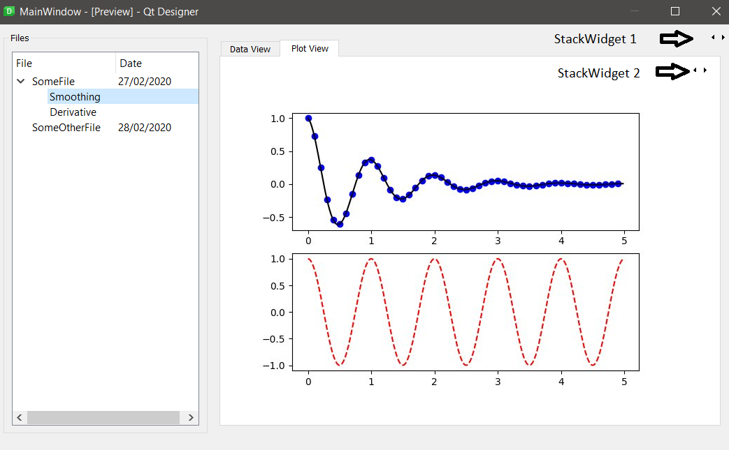
Figure 3: PyQt5 interface example.
Overview of Python Libraries Used
The development of the interface involved multiple Python libraries, each responsible for a different aspect of the application. Below is a brief summary:
- PyQt5: Provides all GUI components and handles the event-driven architecture of the interface.
- PySerial: Manages the serial communication between the computer and the microcontroller via USB. It enables sending commands and receiving sensor data.
- Threading: Ensures that background serial reading does not freeze the GUI. It allows parallel tasks while keeping the interface responsive.
- Math: Used for numerical operations, especially for interpreting sensor readings (e.g., computing angles from accelerometer data).
- Pygame + OpenGL: Optional modules used for rendering 3D visualizations of motion data in real time. They help in representing pitch, roll, or yaw.
This combination of libraries enables a dynamic interface capable of reading sensor input, sending actuator commands, and visualizing feedback without interrupting user interaction.
Microcontroller and Communication Overview
Now, I will briefly examine how the microcontrollers code handles communication and hardware control, before moving into a block-by-block explanation of the GUI code structure.
The code is in C++ compiled in the Arduino IDE and is very simple, it listens to serial data and controls a NeoPixel LED and a servo motor accordingly. It also sends back sensor readings (from the MPU6050) that the GUI can interpret and display.
        // Include required libraries for the components used
        #include <Adafruit_NeoPixel.h>
        #include <Servo.h>
        #include <Wire.h>
        #include <Adafruit_MPU6050.h>
        #include <Adafruit_Sensor.h>

        // Define NeoPixel pin and power pin
        #define NEOPIXEL_PIN 12
        #define NEO_PWR_PIN 11
        #define NUMPIXELS 1

        // Create instances for LED strip, servo motor and sensor
        Adafruit_NeoPixel pixels(NUMPIXELS, NEOPIXEL_PIN, NEO_GRB + NEO_KHZ800);
        Servo SM;
        Adafruit_MPU6050 mpu;

        // UART communication variables
        String Save_S = "";
        String Sub_1 = "";
        char Det = ' ';
        char Decide;
        int I_end;
        int I_start = 0;

        unsigned long lastReadTime = 0;
        const unsigned long readInterval = 20;

        // Struct to store incoming data from PC (RGB, Angle, Servo status)
        typedef struct {
          int Angle = 90;
          int R = 255;
          int G = 0;
          int B = 0;
          bool S = false;
        } XIAO_DATA_RECV;

        // Struct to store outgoing data from sensor (acceleration and gyro)
        typedef struct {
          int Acc_x = 0;
          int Acc_y = 0;
          int Acc_z = 0;
          int Gyro_x = 0;
          int Gyro_y = 0;
          int Gyro_z = 0;
        } XIAO_DATA_SENT;

        XIAO_DATA_RECV Data_esp;
        XIAO_DATA_SENT Data_hub;

        // Function to move to the next segment in the received string
        void NextString() {
          I_start = I_end + 1;
          Save_S = Save_S.substring(I_start);
          I_start = 0;
          I_end = Save_S.indexOf(Det);
        }

        void setup() {
          Serial.begin(115200);
          SM.attach(D0);

          pinMode(NEO_PWR_PIN, OUTPUT);
          digitalWrite(NEO_PWR_PIN, HIGH);
          pixels.begin();
          pixels.show();

          if (!mpu.begin()) {
            while (1) delay(10);
          }

          mpu.setAccelerometerRange(MPU6050_RANGE_8_G);
          mpu.setGyroRange(MPU6050_RANGE_500_DEG);
          mpu.setFilterBandwidth(MPU6050_BAND_21_HZ);

          delay(1000);
        }

        void loop() {
          // 1. Read sensor data
          unsigned long currentTime = millis();
          if (currentTime - lastReadTime >= readInterval) {
            lastReadTime = currentTime;

            sensors_event_t a, g, temp;
            mpu.getEvent(&a, &g, &temp);

            Data_hub.Acc_x = (int)a.acceleration.x;
            Data_hub.Acc_y = (int)a.acceleration.y;
            Data_hub.Acc_z = (int)a.acceleration.z;

            Data_hub.Gyro_x = (int)g.gyro.x;
            Data_hub.Gyro_y = (int)g.gyro.y;
            Data_hub.Gyro_z = (int)g.gyro.z;

            Serial.print("Ax" + String(Data_hub.Acc_x) + Det);
            Serial.print("Ay" + String(Data_hub.Acc_y) + Det);
            Serial.print("Az" + String(Data_hub.Acc_z) + Det);
            Serial.print("Gx" + String(Data_hub.Gyro_x) + Det);
            Serial.print("Gy" + String(Data_hub.Gyro_y) + Det);
            Serial.println("Gz" + String(Data_hub.Gyro_z));
          }

          // 2. Read incoming UART commands
          if (Serial.available() > 0) {
            Save_S = Serial.readStringUntil('\n') + Det;
            I_end = Save_S.indexOf(Det);

            while (I_end > 0) {
              Sub_1 = Save_S.substring(I_start, I_end);
              Decide = Sub_1.charAt(0);

              if (Decide == 'A') Data_esp.Angle = Sub_1.substring(1, I_end).toInt();
              if (Decide == 'R') Data_esp.R = Sub_1.substring(1, I_end).toInt();
              if (Decide == 'G') Data_esp.G = Sub_1.substring(1, I_end).toInt();
              if (Decide == 'B') Data_esp.B = Sub_1.substring(1, I_end).toInt();
              if (Decide == 'S') Data_esp.S = Sub_1.substring(1, I_end).toInt();

              NextString();
            }
          }

          // 3. Apply RGB and Servo angle
          pixels.setPixelColor(0, pixels.Color(Data_esp.R, Data_esp.G, Data_esp.B));
          pixels.show();

          if (Data_esp.S) SM.write(Data_esp.Angle);
        }
1. Included Libraries
The following libraries are included to support sensor reading, NeoPixel control, and servo operation:
- Adafruit_NeoPixel.h: Enables control of RGB LEDs with various color formats.
- Servo.h: Provides easy control for standard servos.
- Wire.h: Facilitates I2C communication, required by the MPU6050.
- Adafruit_MPU6050.h and Adafruit_Sensor.h: Used to initialize and read data from the MPU6050 (accelerometer + gyroscope).
2. Variable and Object Definitions
These are the core objects and variables declared to manage hardware and communication:
- pixels: Controls a single NeoPixel LED connected to pin 12.
- SM: Servo motor instance connected to pin D0.
- mpu: Sensor object to access accelerometer and gyroscope data.
- Save_S, >Sub_1: Used to temporarily store and process incoming serial strings.
- Data_esp: Struct that stores received values (angle, RGB, and a boolean flag for servo control).
- Data_hub: Struct that holds sensor readings to be sent back to the main controller.
3. Setup Function
The setup() function initializes all hardware components:
- Begins serial communication at 115200 baud.
- Attaches the servo motor to its respective pin.
- Enables power to the NeoPixel and initializes its configuration.
- Initializes the MPU6050 sensor and sets its sensitivity and filtering parameters.
- Adds a small delay to ensure everything stabilizes.
4. Loop Function
The loop() function performs two main tasks: sending sensor data and receiving control commands.
4.1 Sending Sensor Data
Every 20 milliseconds, the code checks if enough time has passed since the last reading. If so, it captures the accelerometer and gyroscope data from the MPU6050 and sends it via UART using a delimited string format.
Serial.print("Ax" + String(Data_hub.Acc_x) + Det);
Each data point is labeled (e.g., Ax, Gx) and followed by a delimiter character for easy parsing on the receiving side.
4.2 Receiving Serial Commands
The code listens for incoming strings terminated with a newline character. Once a complete message is received, it's processed using a while-loop and the function NextString() to extract segments one by one.
- Each segment starts with a character (e.g.,
'R','A','S') indicating the data type. - The corresponding value is parsed and stored in
Data_esp.
4.3 Acting on Received Data
Once the incoming values are processed:
- The RGB values are applied to the NeoPixel using
pixels.setPixelColor(). - If the flag
Data_esp.Sis true, the servo is moved to the specified angle usingSM.write().
5. Auxiliary Function: NextString()
This small utility function is used to advance through the serial string buffer by identifying the next delimiter and updating indices accordingly. It allows efficient parsing of multiple values received in a single string (I also created this function because I initially thought I'd be repeatedly generating many substrings. Therefore, it would be easier to manage everything in one function).
void NextString() {
          I_start = I_end + 1;
          Save_S = Save_S.substring(I_start);
          I_start = 0;
          I_end = Save_S.indexOf(Det);
        }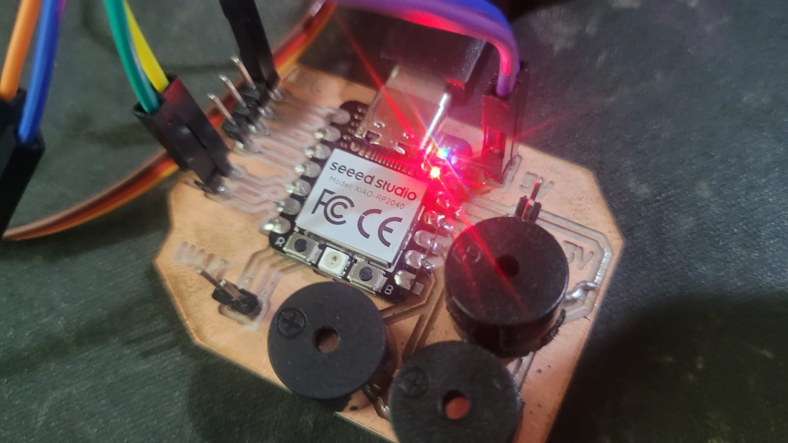
Figure 4: XIAO connections (It is practically the same as with week 11).
PyQt5 GUI Fundamentals and Serial Communication
This section explains the foundational elements of the GUI built with PyQt5 used in the project, particularly focusing on how widgets are created and managed, as well as how serial communication is implemented in a non-blocking and responsive way.
Essential Libraries and Their Roles
| Library | Purpose | Key Elements Used |
|---|---|---|
PyQt5.QtWidgets |
Provides GUI components like windows, sliders, buttons, etc. |
|
PyQt5.QtCore |
Manages signals, threads, and application logic |
|
PyQt5.QtGui |
Handles visuals and styles |
|
serial / serial.tools.list_ports |
Detects available COM ports and manages UART communication |
|
Common PyQt Widgets Explained
The GUI consists of a mix of interactive widgets. Here's how they behave and interact in the application:
| Widget | Description | Usage in App |
|---|---|---|
QSlider |
A horizontal or vertical slider to choose values in a range | Used for selecting RGB values from 0 to 255 |
QDial |
Rotational input widget to select angular values | Controls the servo angle (0°–180°) |
QSpinBox |
Numeric input with up/down arrows | Synchronized with the dial for precise angle selection |
QPushButton |
Clickable button, optionally toggleable | Starts/stops servo and opens color picker |
QColorDialog |
Opens a window for color selection | Sets RGB sliders to selected color and updates preview |
QComboBox |
Dropdown list to choose between options | Selects the available COM port to open |
QLabel |
Displays static or dynamic text | Shows sensor data and status messages |
The real code...
  import sys, time, math, threading
  import serial
  import serial.tools.list_ports

  # PyQt5: GUI framework
  from PyQt5.QtWidgets import (
      QApplication, QMainWindow, QWidget, QLabel, QSlider, QDial,
      QPushButton, QColorDialog, QHBoxLayout, QVBoxLayout, QSpinBox,
      QFrame, QComboBox
  )
  from PyQt5.QtCore import Qt, QThread, QObject, pyqtSignal, pyqtSlot, QTimer
  from PyQt5.QtGui import QPalette, QColor, QFont, QIcon

  # PyOpenGL and Pygame: For 3D visualizer
  from OpenGL.GL import *
  from OpenGL.GLU import *
  import pygame
  from pygame.locals import *

  # Serial communication class in a separate thread
  class SerialWorker(QObject):
      data_received = pyqtSignal(str)  # Signal emitted when data is received from serial port

      def __init__(self, port):
          super().__init__()
          try:
              # Try to open the selected serial port
              self.ser = serial.Serial(port, 115200, timeout=0.1)
              self.connected = True
          except Exception:
              self.ser = None
              self.connected = False

      @pyqtSlot()
      def run(self):
          # Main loop to continuously read serial data
          if not self.connected:
              return
          while True:
              try:
                  line = self.ser.readline().decode(errors='ignore').strip()
                  if line:
                      self.data_received.emit(line)
                  time.sleep(0.005)
              except:
                  break

  # Main application window class
  class MainWindow(QMainWindow):
      def __init__(self):
          super().__init__()
          self.setWindowTitle("Xiao RP2040 Control")
          self.setMinimumSize(850, 620)

          # Variables for 3D orientation
          self.pitch = self.roll = self.yaw = 0
          self.pitch_f = self.roll_f = self.yaw_f = 0
          self.alpha = 0.2  # Filter coefficient for smoothing
          self.worker = None  # Serial worker
          self.thread = None  # Serial thread

          # RGB sliders for color selection
          self.sliders = {}
          for color in ('R','G','B'):
              slider = QSlider(Qt.Horizontal)
              slider.setRange(0,255)
              slider.valueChanged.connect(self.send_all_data)
              self.sliders[color] = slider

          # Color picker button and preview box
          self.btn_color = QPushButton("Choose the color")
          self.btn_color.clicked.connect(self.choose_color)
          self.lbl_preview = QLabel()
          self.lbl_preview.setFixedSize(50, 50)
          self.lbl_preview.setStyleSheet("border: 1px solid white;")

          # Dial and spin box for angle selection (0-180 degrees)
          self.dial = QDial()
          self.dial.setRange(0, 180)
          self.dial.setFixedSize(100, 100)
          self.spin = QSpinBox()
          self.spin.setRange(0, 180)
          self.dial.valueChanged.connect(self.spin.setValue)
          self.spin.valueChanged.connect(self.dial.setValue)
          self.dial.valueChanged.connect(self.send_all_data)

          # Servo ON/OFF button
          self.btn_servo = QPushButton("Servo OFF")
          self.btn_servo.setCheckable(True)
          self.btn_servo.setIcon(QIcon.fromTheme("media-playback-start"))
          self.btn_servo.toggled.connect(self.toggle_servo)

          # Labels to show sensor values
          self.lbls = {k: self._build_data_label(k) for k in ["Ax", "Ay", "Az", "Gx", "Gy", "Gz"]}

          # COM port selection and initialization
          self.combo_ports = QComboBox()
          self.combo_ports.addItems([port.device for port in serial.tools.list_ports.comports()])
          self.combo_ports.setStyleSheet("color: white; background-color: #3A3A3A;")
          self.btn_init = QPushButton("Initialize")
          self.btn_init.clicked.connect(self.init_serial)
          self.lbl_status = QLabel("")
          self.lbl_status.setAlignment(Qt.AlignCenter)

          # Layout setup
          main = QVBoxLayout()

          # Layout for color sliders and color picker
          color_layout = QHBoxLayout()
          for s in self.sliders.values():
              color_layout.addWidget(s)
          color_layout.addWidget(self.btn_color)
          color_layout.addWidget(self.lbl_preview)
          main.addLayout(color_layout)

          # Layout for angle control (dial + spinbox) and servo button
          servo_layout = QHBoxLayout()
          servo_layout.addWidget(self.dial)
          servo_layout.addWidget(self.spin)
          servo_layout.addWidget(self.btn_servo)
          main.addLayout(servo_layout)

          # Layout for IMU data display
          sensor_layout = QHBoxLayout()
          for l in self.lbls.values():
              sensor_layout.addWidget(l)
          main.addLayout(sensor_layout)

          # Layout for COM port selection and button
          com_layout = QHBoxLayout()
          com_layout.addStretch()
          com_layout.addWidget(self.combo_ports)
          com_layout.addWidget(self.btn_init)
          com_layout.addStretch()
          main.addLayout(com_layout)

          # Layout for connection status label
          status_layout = QHBoxLayout()
          status_layout.addStretch()
          status_layout.addWidget(self.lbl_status)
          status_layout.addStretch()
          main.addLayout(status_layout)

          # Final setup for the central widget
          container = QWidget()
          container.setLayout(main)
          self.setCentralWidget(container)

          # Timer for sending servo data every 200ms when ON
          self.servoTimer = QTimer()
          self.servoTimer.timeout.connect(self.send_all_data)

          # Start 3D visualizer in a separate thread
          threading.Thread(target=self.visualizer_loop, daemon=True).start()

      # Create label for displaying sensor data
      def _build_data_label(self, key):
          frame = QFrame()
          frame.setStyleSheet("background-color: #3A3A3A; border-radius: 10px; padding: 10px;")
          layout = QVBoxLayout()
          label = QLabel(f"{key}: 0")
          label.setAlignment(Qt.AlignCenter)
          label.setStyleSheet("font-size: 16px; font-weight: bold; color: white;")
          layout.addWidget(label)
          frame.setLayout(layout)
          return frame

      # Initialize selected COM port
      def init_serial(self):
          port = self.combo_ports.currentText()
          try:
              temp_worker = SerialWorker(port)
              if temp_worker.connected:
                  self.worker = temp_worker
                  self.thread = QThread()
                  self.worker.moveToThread(self.thread)
                  self.thread.started.connect(self.worker.run)
                  self.worker.data_received.connect(self.update_sensors)
                  self.thread.start()
                  self.lbl_status.setText("\u2705 Success Init")
              else:
                  self.lbl_status.setText("\u274C Init Failed, verify COM")
          except Exception:
              self.lbl_status.setText("\u274C Error while initializing COM")

      # Open color picker and apply selected color
      def choose_color(self):
          color = QColorDialog.getColor()
          if color.isValid():
              r, g, b, _ = color.getRgb()
              self.sliders['R'].setValue(r)
              self.sliders['G'].setValue(g)
              self.sliders['B'].setValue(b)
              self.lbl_preview.setStyleSheet(f"background: rgb({r},{g},{b}); border: 1px solid white;")

      # Toggle servo ON/OFF and start/stop timer
      def toggle_servo(self, on):
          self.btn_servo.setText("Servo ON" if on else "Servo OFF")
          if on:
              self.servoTimer.start(200)
          else:
              self.servoTimer.stop()
              self.send_all_data()

      # Send data over serial: RGB values, angle, and servo status
      def send_all_data(self):
          if not self.worker or not self.worker.connected:
              return
          try:
              r = self.sliders['R'].value()
              g = self.sliders['G'].value()
              b = self.sliders['B'].value()
              a = self.dial.value()
              s = 1 if self.btn_servo.isChecked() else 0
              msg = f"A{a} R{r} G{g} B{b} S{s}\n"
              self.lbl_preview.setStyleSheet(f"background: rgb({r},{g},{b}); border: 1px solid white;")
              self.worker.ser.write(msg.encode())
          except:
              pass

      # Update sensor values when new serial data is received
      @pyqtSlot(str)
      def update_sensors(self, line):
          values = {}
          for part in line.strip().split():
              for key, frame in self.lbls.items():
                  if part.startswith(key):
                      val = part[len(key):]
                      frame.layout().itemAt(0).widget().setText(f"{key}: {val}")
                      values[key] = int(val)
          try:
              ax = values['Ax'] / 9.81
              ay = values['Ay'] / 9.81
              az = values['Az'] / 9.81
              pitch = math.atan2(ax, math.sqrt(ay**2 + az**2)) * 180 / math.pi
              roll  = math.atan2(ay, math.sqrt(ax**2 + az**2)) * 180 / math.pi
              yaw   = self.yaw + values['Gz'] * 0.02
              self.pitch_f = self.alpha * pitch + (1 - self.alpha) * self.pitch_f
              self.roll_f  = self.alpha * roll  + (1 - self.alpha) * self.roll_f
              self.yaw_f   = self.alpha * yaw   + (1 - self.alpha) * self.yaw_f
              self.pitch, self.roll, self.yaw = self.pitch_f, self.roll_f, self.yaw_f
          except:
              pass

      # 3D visualizer showing orientation of a cube using pitch, roll, yaw
      def visualizer_loop(self):
          pygame.init()
          screen = pygame.display.set_mode((400, 400), DOUBLEBUF | OPENGL)
          pygame.display.set_caption("3D Orientation")
          glEnable(GL_DEPTH_TEST)
          glMatrixMode(GL_PROJECTION)
          glLoadIdentity()
          gluPerspective(45, 1, 0.1, 50.0)
          glMatrixMode(GL_MODELVIEW)
          glLoadIdentity()
          while True:
              for event in pygame.event.get():
                  if event.type == pygame.QUIT:
                      pygame.quit()
                      return
              glClear(GL_COLOR_BUFFER_BIT | GL_DEPTH_BUFFER_BIT)
              glLoadIdentity()
              glTranslatef(0.0, 0.0, -5.0)
              glRotatef(self.yaw, 0, 1, 0)
              glRotatef(self.pitch, 1, 0, 0)
              glRotatef(-self.roll, 0, 0, 1)
              glBegin(GL_QUADS)
              glColor3f(0.6,0.2,0.2)
              glVertex3f(1,1,-1); glVertex3f(-1,1,-1); glVertex3f(-1,1,1); glVertex3f(1,1,1)
              glColor3f(0.2,0.6,0.2)
              glVertex3f(1,-1,1); glVertex3f(-1,-1,1); glVertex3f(-1,-1,-1); glVertex3f(1,-1,-1)
              glColor3f(0.2,0.2,0.6)
              glVertex3f(1,1,1); glVertex3f(-1,1,1); glVertex3f(-1,-1,1); glVertex3f(1,-1,1)
              glColor3f(0.6,0.6,0.2)
              glVertex3f(1,-1,-1); glVertex3f(-1,-1,-1); glVertex3f(-1,1,-1); glVertex3f(1,1,-1)
              glColor3f(0.6,0.2,0.6)
              glVertex3f(-1,1,1); glVertex3f(-1,1,-1); glVertex3f(-1,-1,-1); glVertex3f(-1,-1,1)
              glColor3f(0.2,0.6,0.6)
              glVertex3f(1,1,-1); glVertex3f(1,1,1); glVertex3f(1,-1,1); glVertex3f(1,-1,-1)
              glEnd()
              pygame.display.flip()
              pygame.time.wait(20)

  # Apply custom dark theme to GUI application
  def apply_dark_burnt_theme(app):
      palette = QPalette()
      palette.setColor(QPalette.Window, QColor("#2E2E2E"))
      palette.setColor(QPalette.Text, QColor("#FFFFFF"))
      palette.setColor(QPalette.Button, QColor("#5C1E1E"))
      palette.setColor(QPalette.ButtonText, QColor("#FFFFFF"))
      palette.setColor(QPalette.Highlight, QColor("#7A2E2E"))
      palette.setColor(QPalette.HighlightedText, QColor("#FFFFFF"))
      app.setPalette(palette)
      font = QFont("Segoe UI", 12)
      app.setFont(font)
      app.setStyleSheet("""
          QPushButton {
              background-color: #7A2E2E;
              border: 1px solid #5C1E1E;
              padding: 8px;
              border-radius: 8px;
              font-weight: bold;
          }
          QPushButton:checked {
              background-color: #A84242;
          }
          QSlider::groove:horizontal {
              border: 1px solid #444;
              height: 8px;
              background: #555;
          }
          QSlider::handle:horizontal {
              background: #AA3E3E;
              border: 1px solid #333;
              width: 18px;
              margin: -4px 0;
              border-radius: 9px;
          }
          QDial {
              background-color: #3A3A3A;
              border: none;
          }
          QSpinBox {
              background-color: #3A3A3A;
              border: 1px solid #5C1E1E;
              padding: 4px;
              border-radius: 4px;
              color: white;
          }
          QLabel {
              font-size: 14px;
          }
          QComboBox {
              background-color: #3A3A3A;
              border: 1px solid #5C1E1E;
              padding: 4px;
              color: white;
          }
          QComboBox QAbstractItemView {
              background-color: #3A3A3A;
              color: white;
          }
      """)

  # Entry point of the program
  if __name__ == '__main__':
      app = QApplication(sys.argv)  # Create the Qt application
      apply_dark_burnt_theme(app)  # Apply custom theme
      win = MainWindow()  # Create main window
      win.show()  # Show window
      sys.exit(app.exec_())  # Start event loop
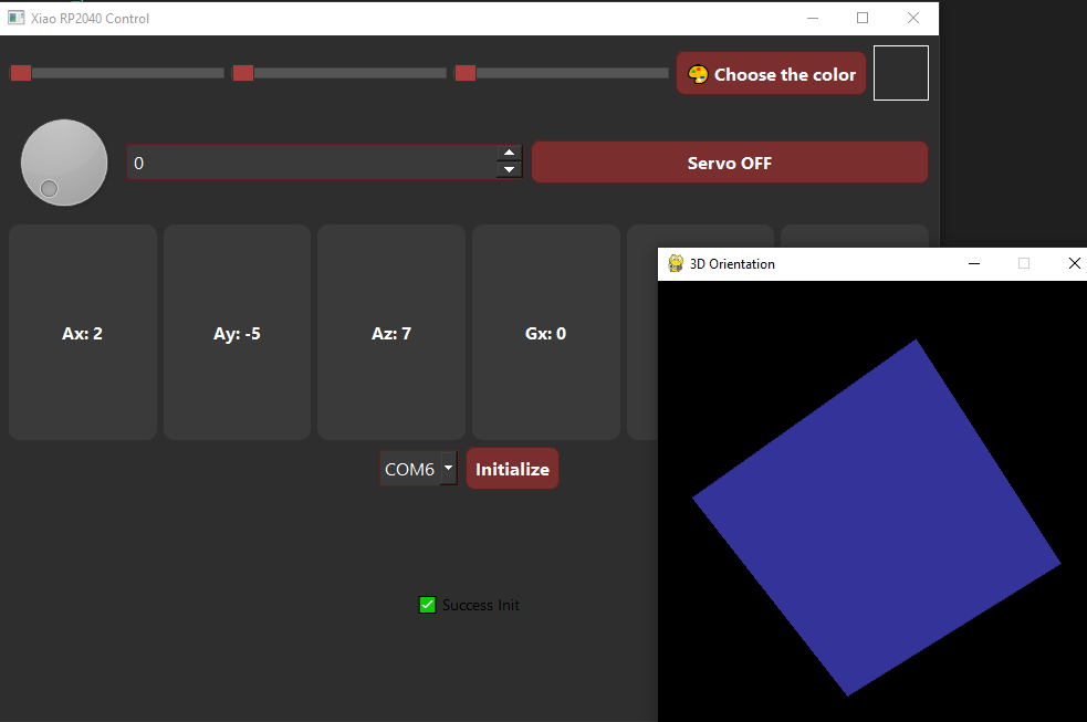
Figure 5: How it looks!.
Color Selection and Preview System
This part of the interface allows the user to control the RGB values of a color using three QSlider widgets (horizontal sliders). Each slider represents one of the Red, Green, or Blue components, and its range is from 0 to 255. When any slider's value changes, the preview QLabel updates its background color using `setStyleSheet` with the selected RGB color. The same RGB values are formatted as a string and transmitted over the serial port through the `send_all_data` method. Additionally, a QColorDialog allows selecting colors graphically; the chosen color is parsed and applied to the sliders and preview box.
Dial and Spinbox for Angle Selection
A QDial and a QSpinBox are configured with the same 0 to 180 range. These two widgets are synchronized bidirectionally: changing the dial updates the spinbox and vice versa. Changes on the dial trigger the `send_all_data` function, which sends the current angle along with RGB values and servo status to the microcontroller over the serial connection.
Servo Control Button
The servo is controlled using a QPushButton with a toggleable state. When pressed, it changes its text from "Servo OFF" to "Servo ON" and starts a QTimer that fires every 200 ms. Each timer tick calls `send_all_data`, ensuring the servo remains updated. When toggled off, the timer stops and a final update is sent to turn off the servo by setting 'S0' in the message string.
Sensor Label Building (_build_data_label)
This method dynamically creates six labeled UI components for the Ax, Ay, Az, Gx, Gy, and Gz values from an IMU sensor. Each label is placed in a QFrame with a dark background, rounded corners, and centered white text. These frames are stored in a dictionary (`self.lbls`) and updated live when new serial data is received.
3D Visualizer using PyOpenGL and Pygame
If you want to learn from an expert, I'll link to a video of SebMadgwickResearch who did the same thing and even took it to the next level. The video itself doesn't explain much, but in the description, he includes a GitHub link with the code he used, which helped me understand this part.
The 3D visualizer runs in a separate thread through the `visualizer_loop()` function to avoid blocking the main GUI thread. It utilizes Pygame to create a rendering window and OpenGL to render a colored cube that reflects the physical orientation of a sensor-equipped device.
OpenGL is initialized with depth testing enabled to ensure correct rendering of the cube's faces. A perspective projection is set using `gluPerspective`, creating a natural 3D view with a field of vision of 45°, aspect ratio of 1:1, and visible range from 0.1 to 50.0 units. The model-view matrix is then reset, and the camera is positioned 5 units backward to ensure the cube is visible.
The camera setup involves translating the entire scene along the Z-axis. This translation simulates the effect of pulling the camera away from the object, ensuring that the cube stays within view and rotates about its own center.
Orientation Application
The cube’s orientation is updated using OpenGL’s `glRotatef()` function based on pitch, roll, and yaw values. These values correspond to real-world sensor data and are applied in sequence to simulate 3D rotation:
- Yaw: rotation around the Y-axis (horizontal turn).
- Pitch: rotation around the X-axis (forward/backward tilt).
- Roll: rotation around the Z-axis (side-to-side tilt).
This transformation order mimics natural motion and maintains intuitive behavior for real-time visualization.
Sensor Data Handling and Rotation Calculation
Sensor readings are received from a serial port, parsed to extract Ax, Ay, Az (acceleration) and Gz (gyroscopic Z-axis). Using trigonometric functions, pitch and roll are derived from the accelerometer:
- Pitch = atan2(ax, sqrt(ay² + az²)) × 180/π
- Roll = atan2(ay, sqrt(ax² + az²)) × 180/π
- Yaw is estimated by integrating Gz over time (assuming a constant time step of 20ms).
To ensure smooth visual feedback, an exponential moving average filter is applied to each angle, the three angles are smoothed using an exponential moving average filter (EMA) with a coefficient alpha (0.2).
Rendering the Cube
The cube is rendered with OpenGL’s `glBegin(GL_QUADS)` and defined with six colored faces. Each face is manually specified with four vertices, and the colors aid in visualizing orientation changes. Because the transformations are applied before rendering, the cube appears to rotate naturally in the 3D space.
Serial Communication
To avoid blocking the GUI while waiting for serial data, this application implements asynchronous serial communication using a QThread and a SerialWorker class:
- SerialWorker: Handles opening the port and reading data.
- run(): Continuously polls the port in a loop, emits a signal with new data.
- data_received signal: Transmits lines read from the port to the main thread safely.
The communication works as follows:
- When the user clicks Initialize, the COM port is opened with
serial.Serial(...). - A separate thread is created to run the reading loop using
QThread. - Incoming lines (e.g.,
"Ax10 Ay0 Az20 Gx5 Gy3 Gz7") are emitted to the main GUI thread. - The GUI parses the data, updates the corresponding labels, and recalculates orientation values (covered later).
Sending data is synchronous and triggered by:
- Changing a slider or dial
- Toggling the servo button
- A timer that periodically sends updates every 200ms
Key Concepts
- Threading: GUI and serial logic must run on different threads to keep the app responsive.
- Signal-Slot Mechanism: PyQt uses signals to safely update UI elements from worker threads.
- QTimer: Used to periodically update servo state without blocking the main loop.
- Encapsulation: Grouping layout, UI creation, and update logic into class methods improves maintainability.
Dark Themed GUI
The function `apply_dark_burnt_theme` styles the entire application using a dark color palette and a custom style sheet. It sets colors for windows, buttons, sliders, spinboxes, combo boxes, and text using QPalette and CSS.
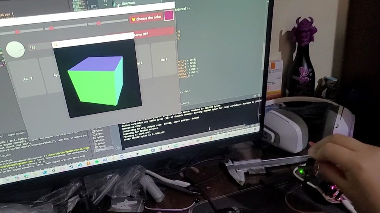
HEROSHOT! INTERFACE.
LEARNINGS
During this week, I learned far more about graphical interfaces than I initially anticipated. Beyond exploring the different types of GUI frameworks available, I focused in particular on PyQt5. Although I already had prior experience programming in Python through other projects, working with graphical interfaces introduced me to a completely new dimension of the language. Managing events, signals, and visual structures requires a distinct logical approach and a specific set of tools provided by the PyQt5 library.
While PyQt5 might seem complex at first glance, it becomes much more approachable once its overall structure is understood. For those beginning to develop interfaces for embedded systems or microcontroller-based applications, I highly recommend exploring PyQt5. Although simpler platforms like MIT App Inventor may offer a more accessible starting point, PyQt5 provides significantly greater flexibility and control over both the design and functionality of the interface.
Additionally, I had the opportunity to work with Pygame and PyOpenGL to build a 3D visualizer. In this process, the code developed by SebMadgwickResearch—whom I discovered through a previously referenced video—proved to be incredibly helpful. His implementation inspired me to pursue real-time motion visualization using sensors like the MPU6050. I had always been interested in this type of representation, and now I understand that, while it is certainly not trivial, it is absolutely achievable. The key lies in properly managing the sensor data and translating it effectively into a meaningful graphical display.