Molding and Casting
Molding and casting are fundamental manufacturing processes used to replicate complex shapes accurately and efficiently. These processes occur in two stages: first, a mold is designed and fabricated containing the desired geometry (molding), and then a liquid material is poured into the mold to take its shape upon solidification (casting).
Types of Molds and Design Considerations
When designing a mold, it's essential to choose the appropriate type based on the intended final piece:
- Positive mold: A 3D representation of the final object, used to create the negative mold.
- Negative mold: A cavity that reflects the exact volume of the desired replica.
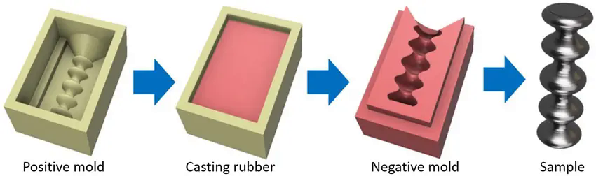
Figure 1: Positive and negative mold comparision
Key design aspects include:
- Uniform wall thickness: Prevents internal stress during curing.
- Pouring channels: Improve material flow and reduce air bubbles.
- Registration/alignment system: Ensures accurate assembly of multi-part molds.
Materials Used
Mold and casting materials should be chosen based on the following criteria:
| Requirement | Mold Material | Casting Material |
|---|---|---|
| Fine detail | RTV silicone | Epoxy resin, polyurethane |
| High temperature | Ceramic plaster, metal | Tin, lead |
| Flexibility required | Silicone, urethane rubber | Gel or soft silicone |
For a deeper look at alternative molding techniques and materials, feel free to check out our group assignment.
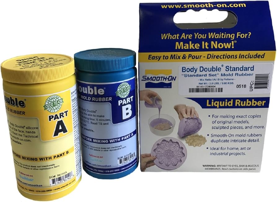
Figure 2: Silicone example
For my week assignment, I decided to print it the mold with PLA and then sand it very well for the finish (post-processing). For casting, I will consider using silicone 3030 due to its strength, flexibility, and fine detail reproduction.
Why “A” and “B” components?
Most molding-grade silicones, such as RTV 3030, are formulated as two-part systems—Component A and Component B—which must be mixed together to trigger the chemical reaction that transforms the material from liquid to solid. This dual-component setup is essential because it enables controlled cross-linking between polymer chains, which is what gives the cured silicone its elasticity, thermal resistance, and ability to capture fine detail.
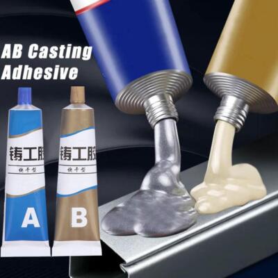
Figure 3: A and B components
Initially, my plan for this week was to mold and cast the beak for my animatronic, which is part of my final project. However, due to its considerable size, I realized it no longer qualifies as a reasonable weekly assignment. Additionally, using silicone for such a large piece would significantly increase the overall weight. While silicone is excellent for capturing fine details, in this case, the added weight doesn't justify the level of detail it offers—the trade-off simply isn't worth it.
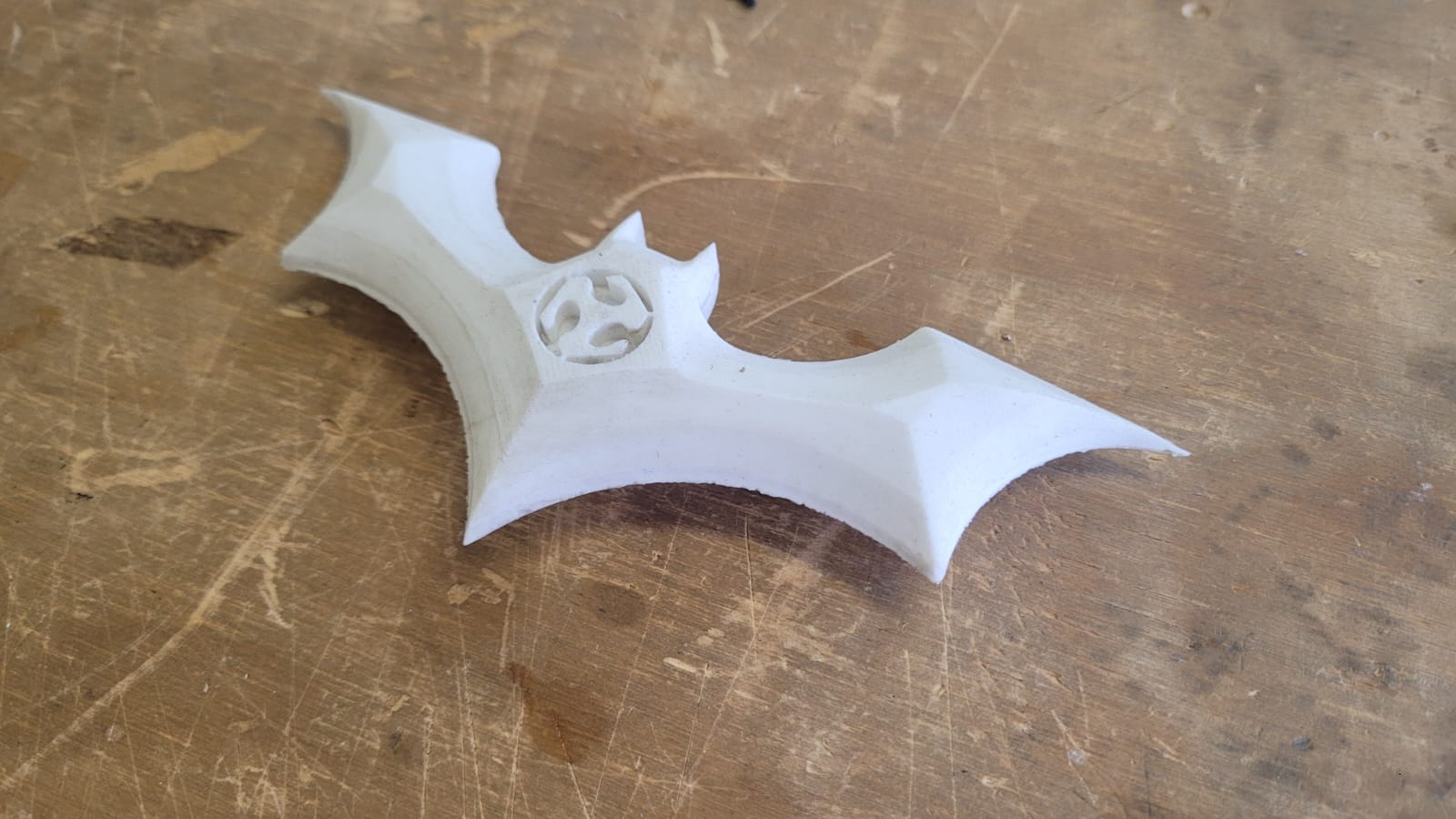
So... I decided to take a more playful approach. While I’ve been working on my final project in the lab, there are moments when things slow down and we end up joking around—or nearly throwing things at each other. So, I figured I’d make something of my own: a small toy that’s durable, harmless, and safe to toss at my friends. That’s how I came up with the idea of creating a batarang-style object—though in the spirit of the Fab Academy, I’ll call it a Fabtarang.
Design!
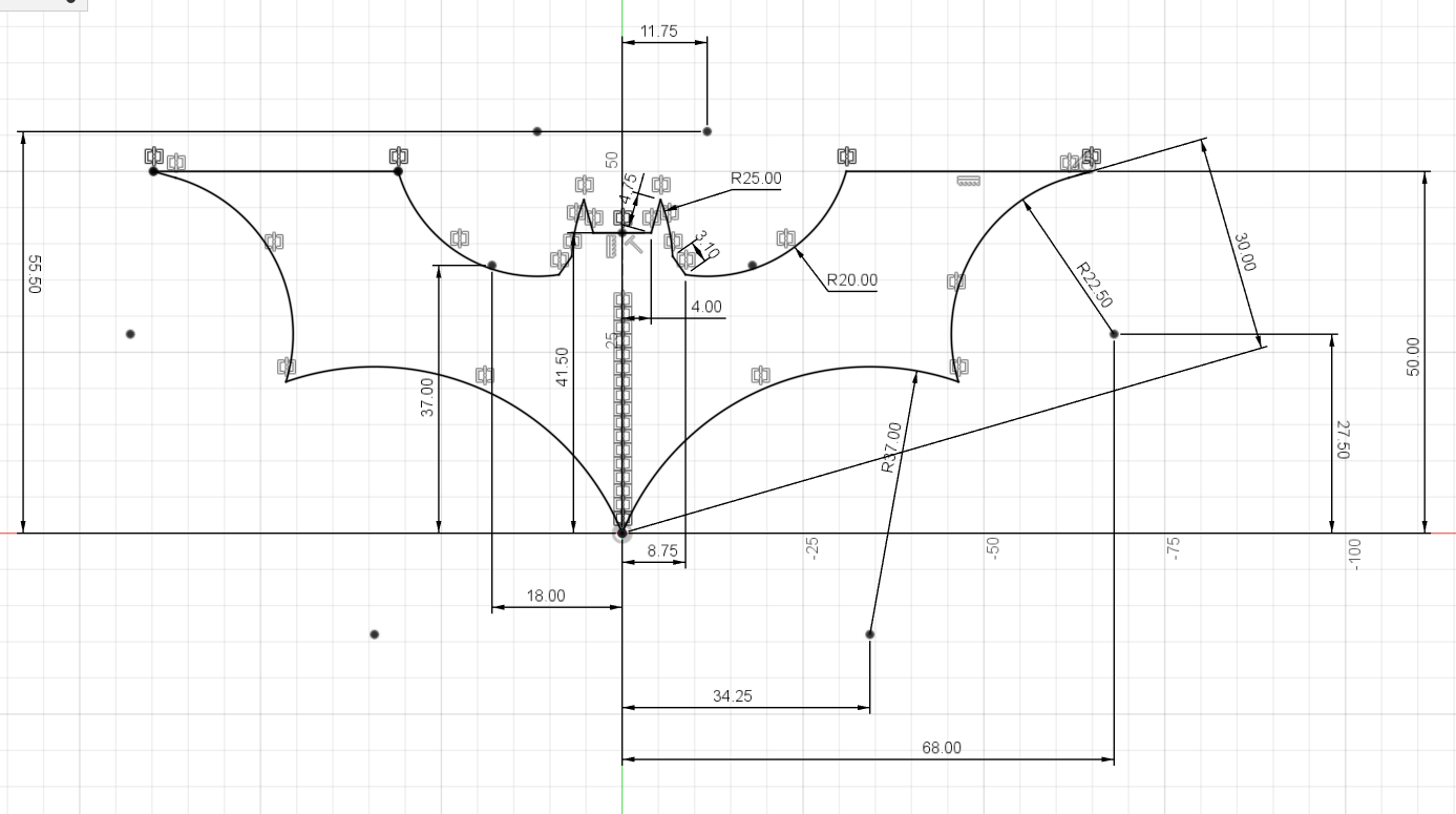
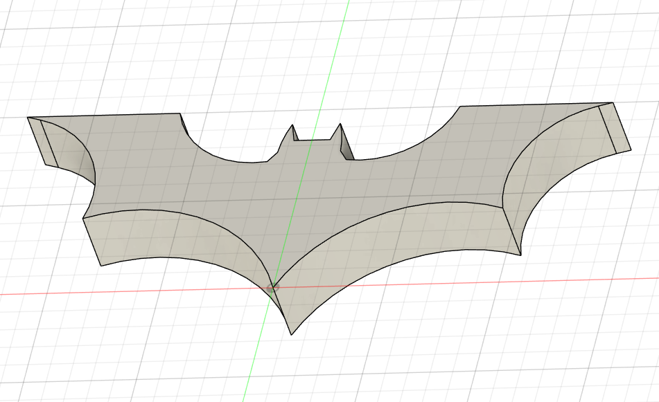
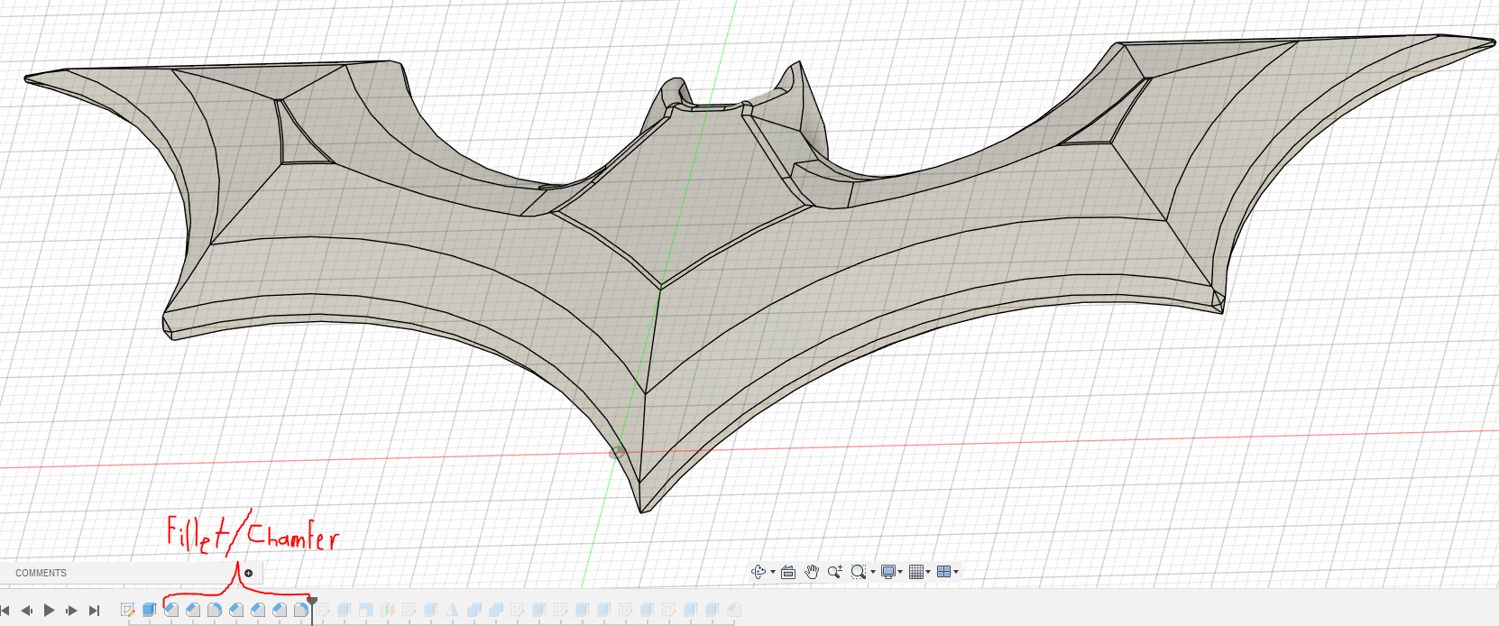
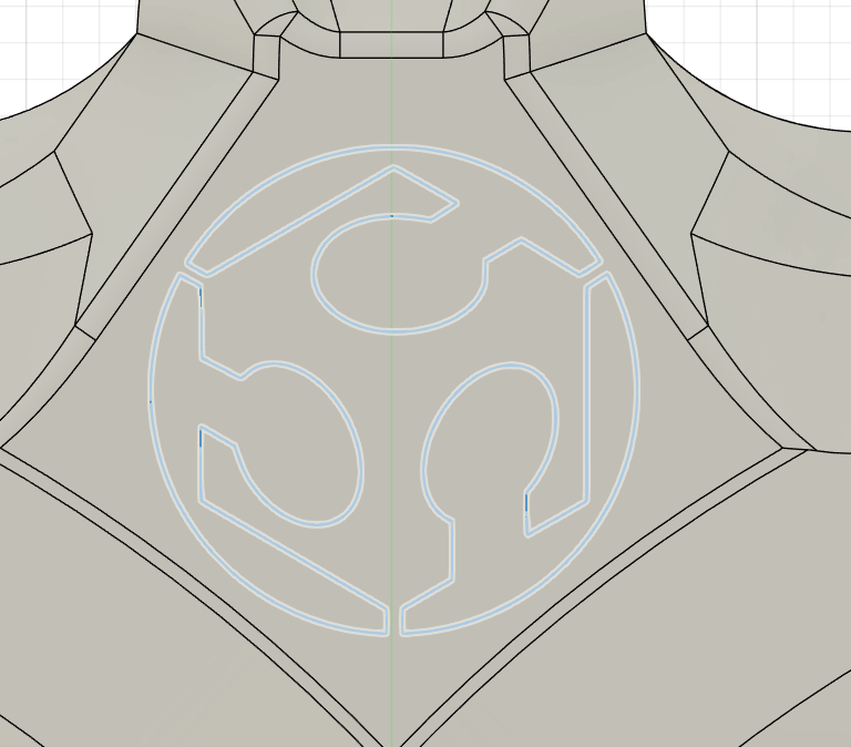
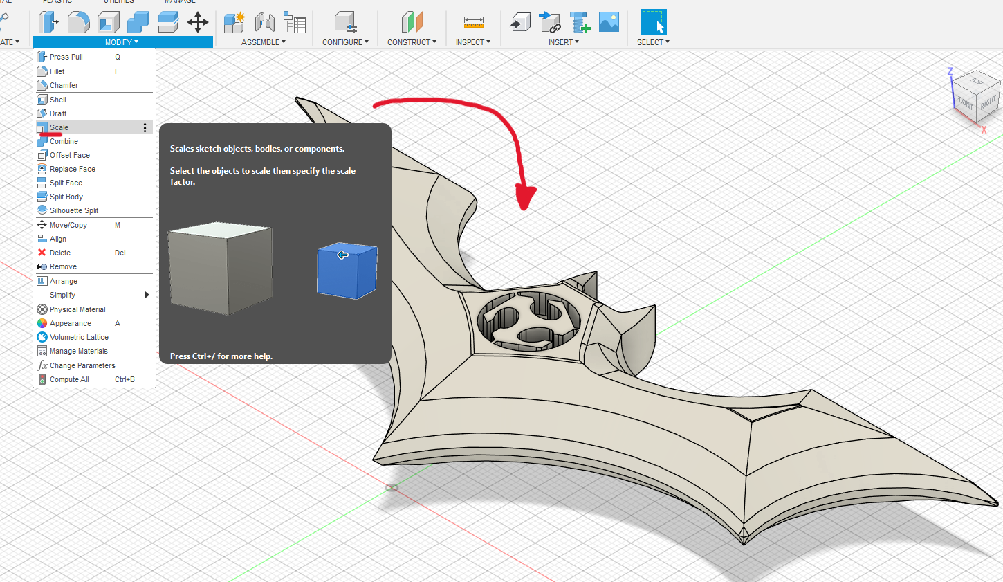
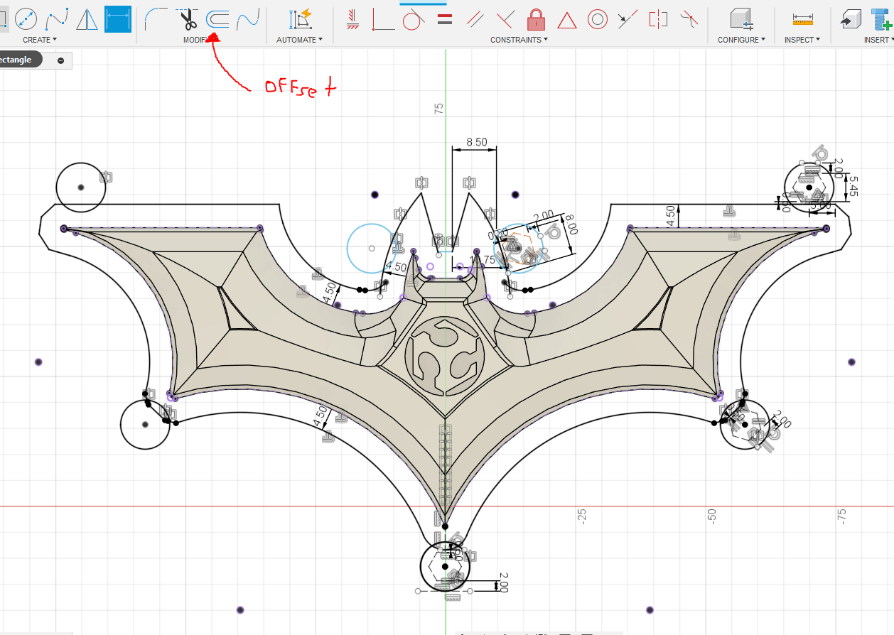
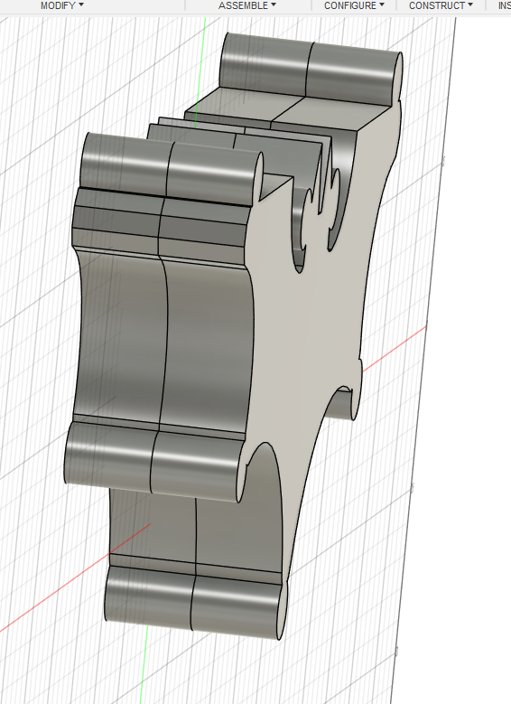
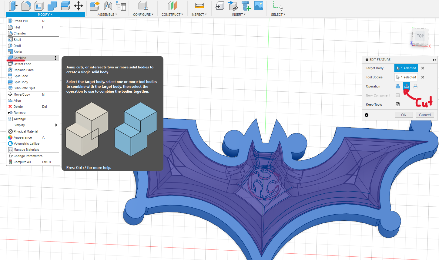
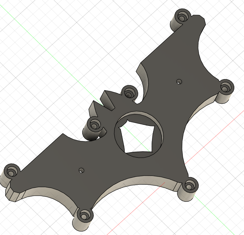
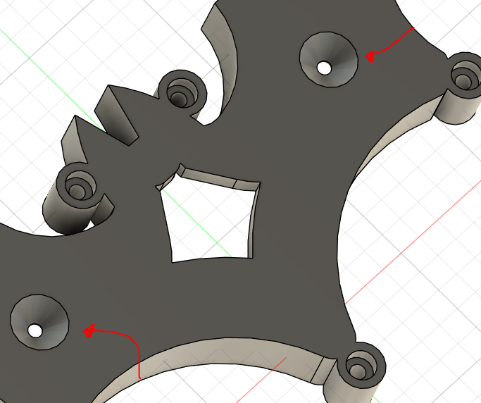
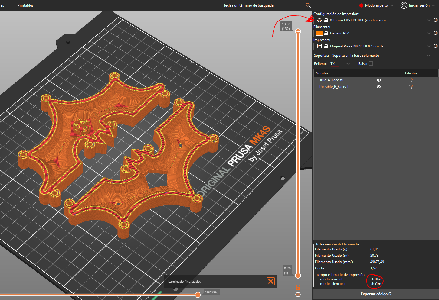
Figure 14: Configuration for the best possible detail of the parts in PrusaSlicer
Safety Considerations
Resins and silicones requires proper personal protection and awareness of associated hazards:
- Nitrile gloves: Prevent direct contact with chemicals.
- Safety goggles: Protect from splashes during mixing or pouring.
- Adequate ventilation: Many silicones and resins release vapors that should not be inhaled in confined spaces.
- Do not use food containers: All utensils must be dedicated to this process only.
It is also advisable to consult the Safety Data Sheets (SDS) (I only founded in German ._.) from the manufacturers. For example, the SDS for silicone 3030 recommends avoiding prolonged skin contact and storing the material in cool, dry environments away from heat or humidity sources.
Silicone Mixing and Application
The RTV silicone 3030 mixing and casting steps were as follows:
- Both components (A and B) were weighed in a 10:1 ratio by weight.
- The mixture was stirred slowly for no more than 5 minutes to minimize bubbles. A vacuum chamber can be used, but a controlled pour from a moderate height is often sufficient.
- The mixture was poured continuously and in a thin stream into the master mold, allowing gravity to reduce air entrapment.
.jpeg)
Figure 15: Sanding the mold for a good finish (I actually sanded it for 3 hours...)
Although the image only shows a single piece of sandpaper, I actually used several throughout the process. As mentioned earlier, achieving a clean and well-defined shape requires significant post-processing. I spent three separate sessions refining both parts of the mold, using sandpaper in progressively finer grits—from 80 up to 600. This gradual increase allowed me to remove imperfections efficiently while improving surface smoothness step by step.
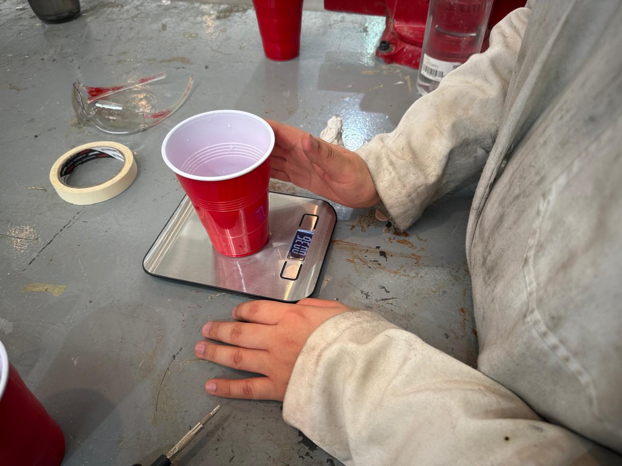
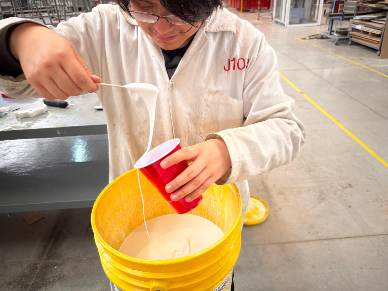
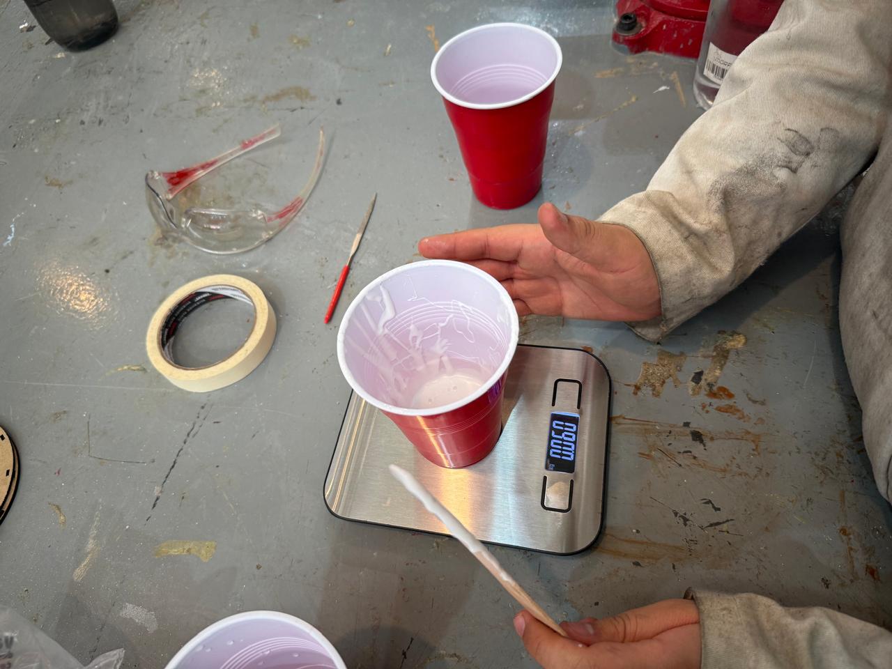
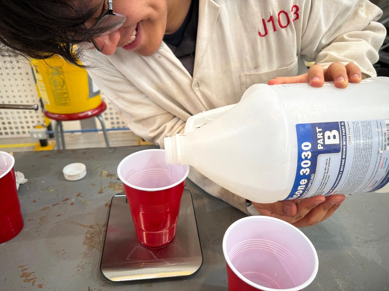
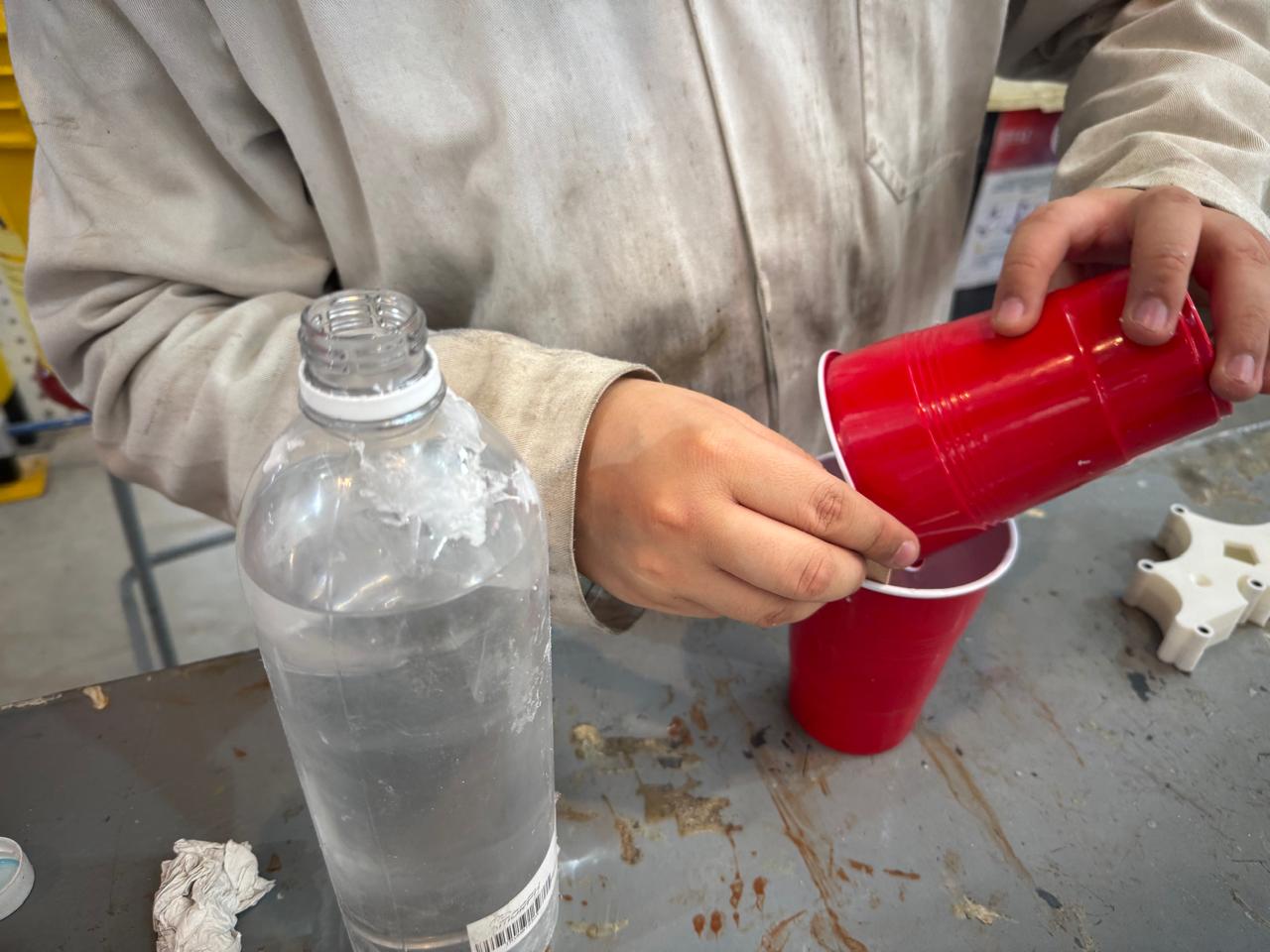
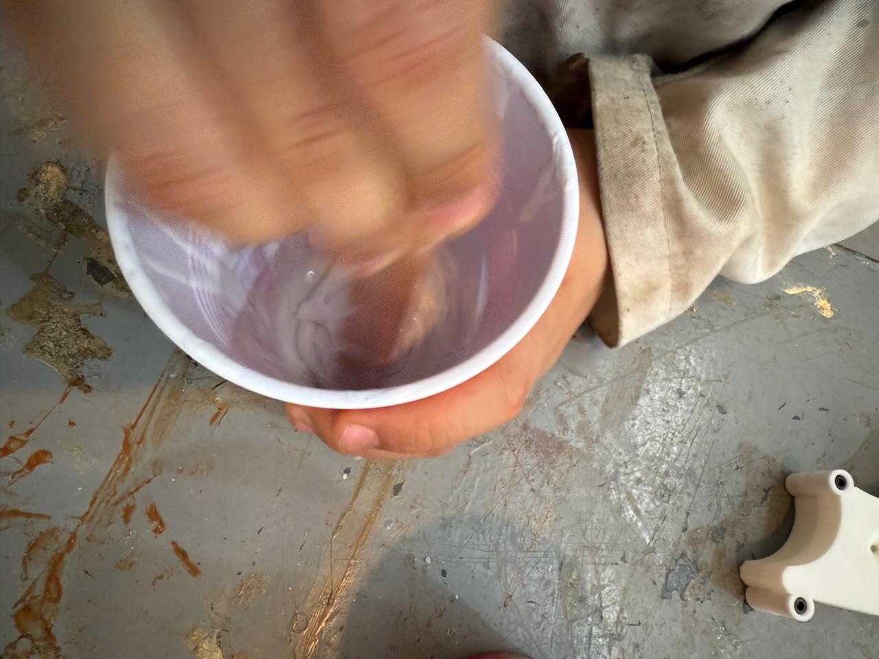
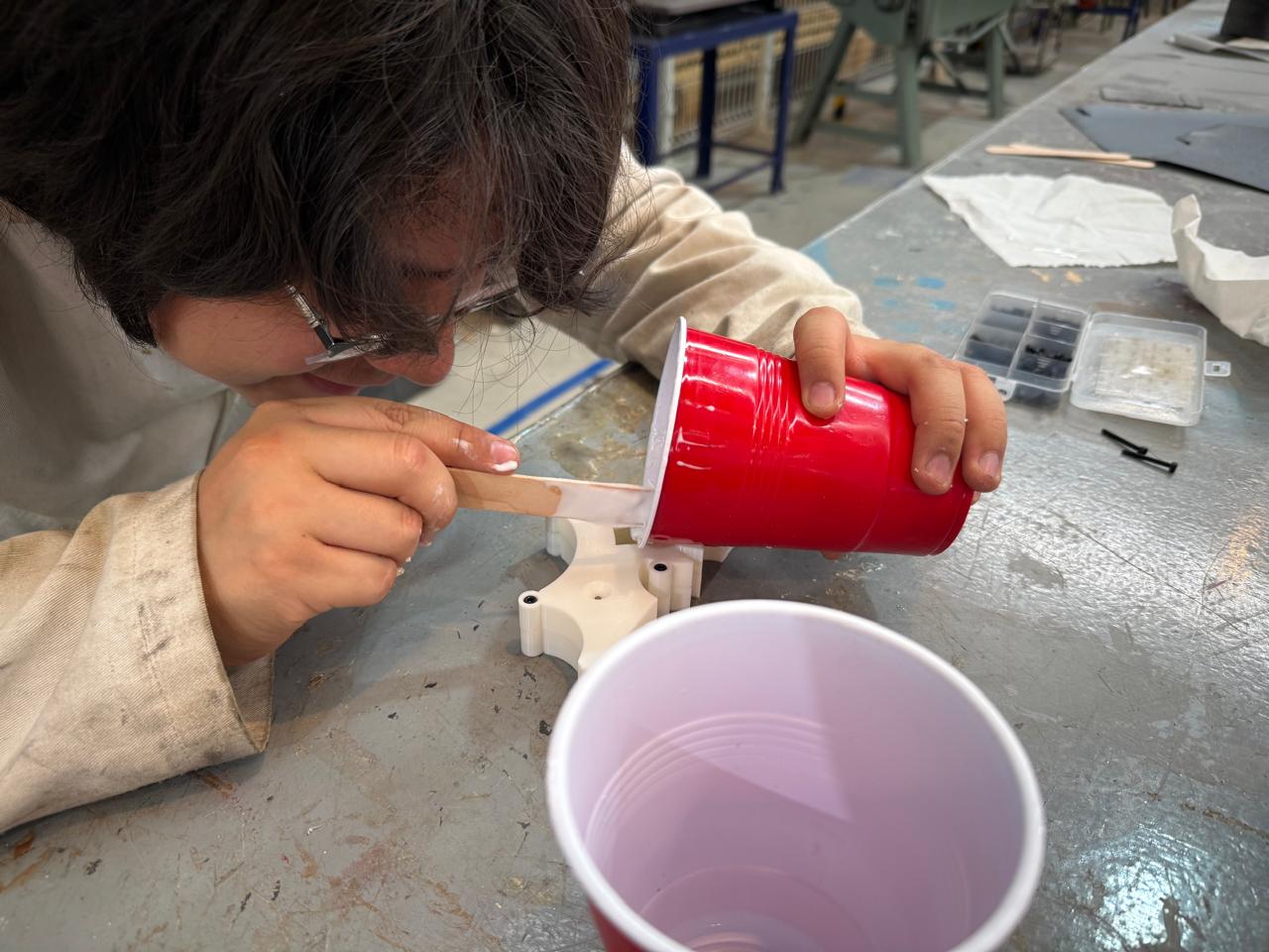
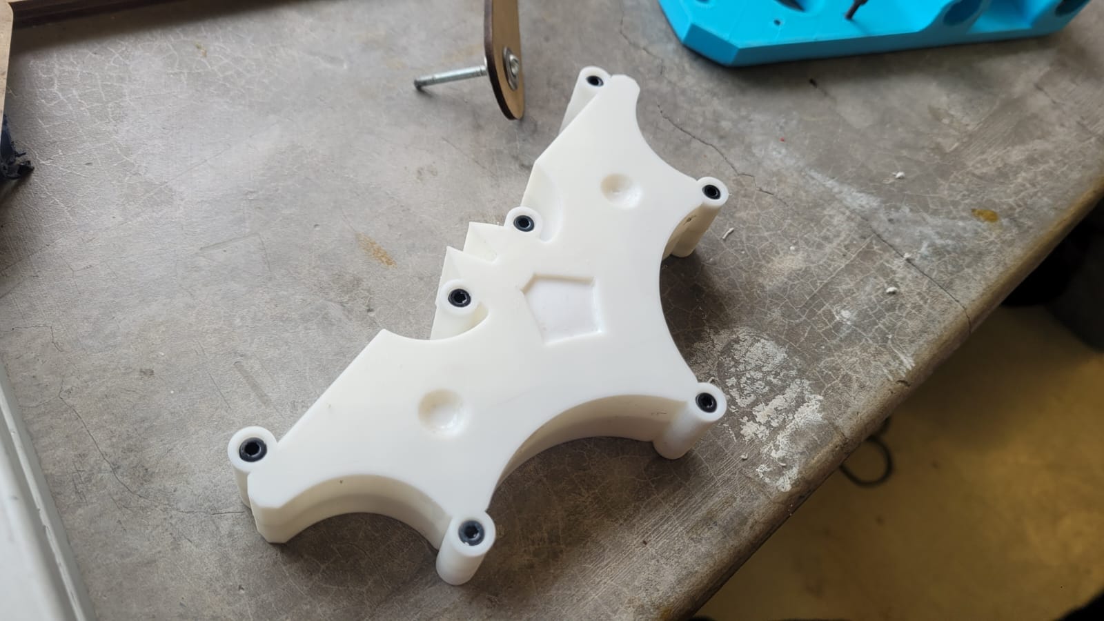
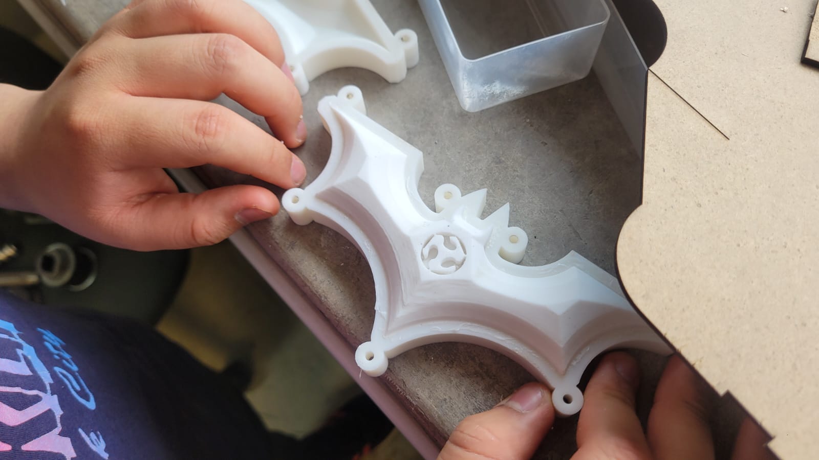
Figure 24: Result after a day of curing
Overall, I'm quite satisfied with the result, although I acknowledge there’s room for improvement. Under certain lighting conditions, a faint line becomes visible on the final piece—an artifact from the layering of filament during the mold’s construction. I believe this occurred because the sanding process wasn’t perfectly uniform. In areas where the surface was more thoroughly sanded, the line is virtually undetectable to both sight and touch.
That said, I consider the outcome a success, especially since the imperfection only appears when the light hits at a specific angle. Under normal viewing conditions, it’s barely noticeable. For future castings, however, I’ll make it a priority to dedicate more time to achieving an even sanding across the entire mold surface.
That said, it’s time to run some clearly necessary tests (⌐■_■)
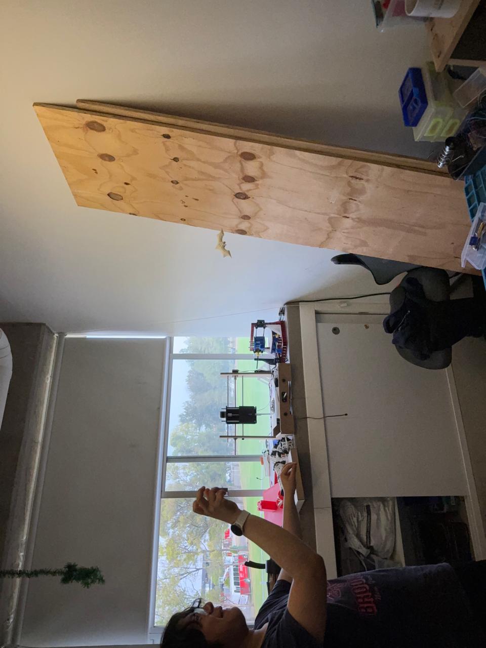
Figure 25: In air!
HEROSHOT! FABTARANG
Learnings
After this week, beyond learning how to create molds and better understanding the mixing and casting process—especially when working with silicone—I’ve noticed a clear improvement in my design skills. Designing the mold felt surprisingly fluid, which made me realize how much progress I’ve made, even after spending a long period away from CAD due to focusing on my project in Blender.
That said, I’m genuinely satisfied with the outcome. Even a week after casting, I still find myself playing with the Fabtarang—and I love it.