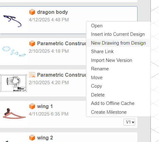
GROUP ASSIGNMENTS
WEEK 3 - Computer-Controlled Cutting
This week we were tasked with characterizing our laser cutters. We set out to record the lasers focus, power, speed, and kerf, in addition joint clearance and types for when we cut out our own parametric construction kits.
Safety Training
As former and current employees of Moonlighter FabLab, Victoria and Augusto have both undergone safety training relating to the laser cutters near the beginning of their employment at the lab. Both went through the Laser Cutting Basics class that we offer with either Tom or Daisy, the founders of the space, and both have completed the neccesary certifications related to operating a Full Spectrum Laser cutting system.
Some of the most important rules to keep in mind for operating laser cutters are -
1. Inspecting laser cutters for breakage or damage before each use.
2. Turning on all auxiliary systems, the air compressor, water chiller, and air exhaust before use. The water chiller is necessary to operate the machine and the other two mitigate potential safety hazards.
3. Never leave laser cutters unattended. Doing so risks create a fire hazard.
4. The red emergency stop button cuts off all power in case of emergencies such as fire hazards. If needed a fire blanket and/or CO2 extinguisher is recommended to put out CO2 laser fires as they are the only approved means of doing so without damaging the equipment.
5. Clean after use. Clear the bed from debris, tapes, jigs, and/or guides to prevent fire hazards. Removing the bed may be necessary.
6. Chemical composition of materials are a good thing to keep in mind. Some materials like PVC and vinyl will harm either you or the machine with toxic and/or corrosive fumes.
7. Keep hands away from moving mechanical parts.
Laser Focus
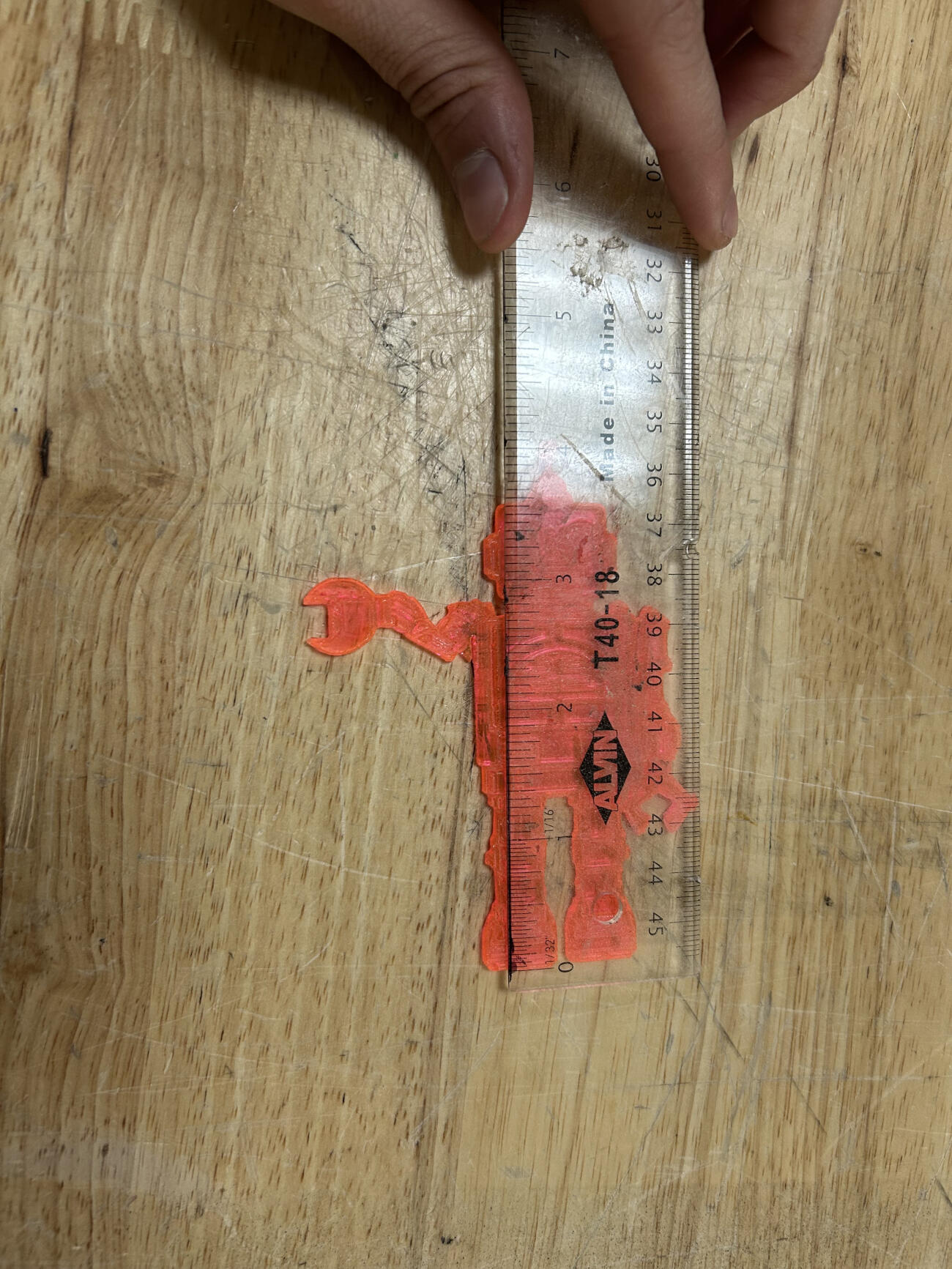
Our laser cutter operates without an auto-focus laser meaning we have to manually measure the distance between the lens and whatever material we cut. With this in mind, we did research on our laser cutter and found out that we are currently operating with a 2.5 lens. The ideal focal distance for a lens of this type is 63.5mm or 2.5 inches. Luckily we already had pre-existing focal ruler templates with our space. We use a robot with a small arm to measure the distance between the midsection of the nozzle, where the lens is located, and the material you are using. To ensure that this ruler was fit for the job we simply measured the distance between its feet and its arm and found that it was 2.5 inches as needed.
Laser Power and Speed
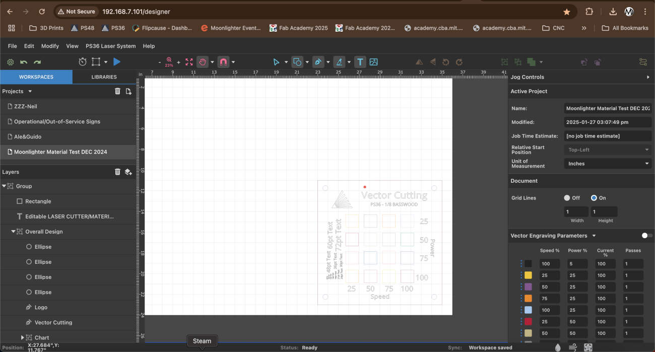
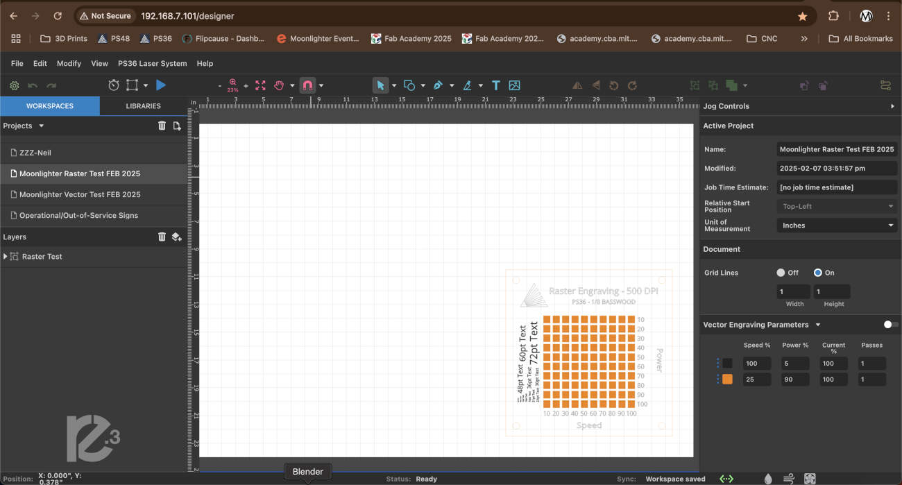
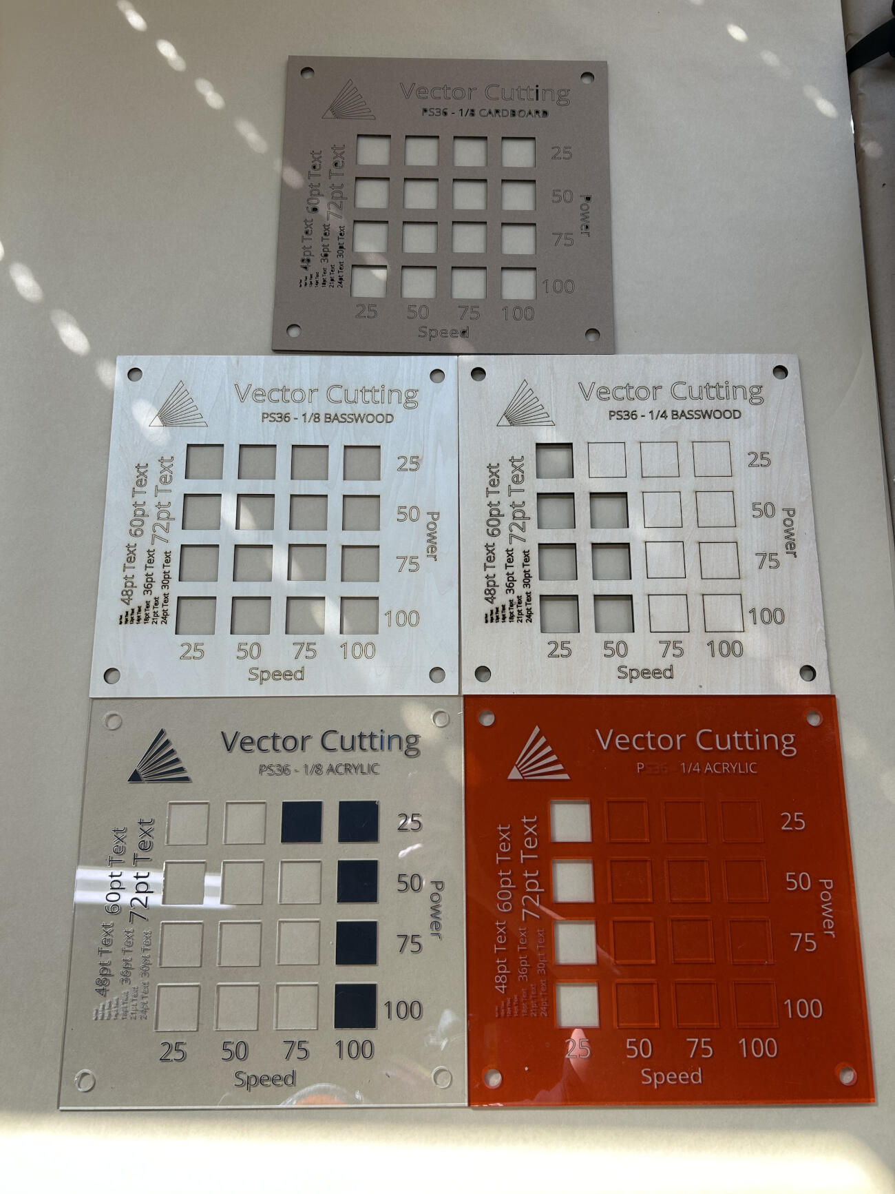
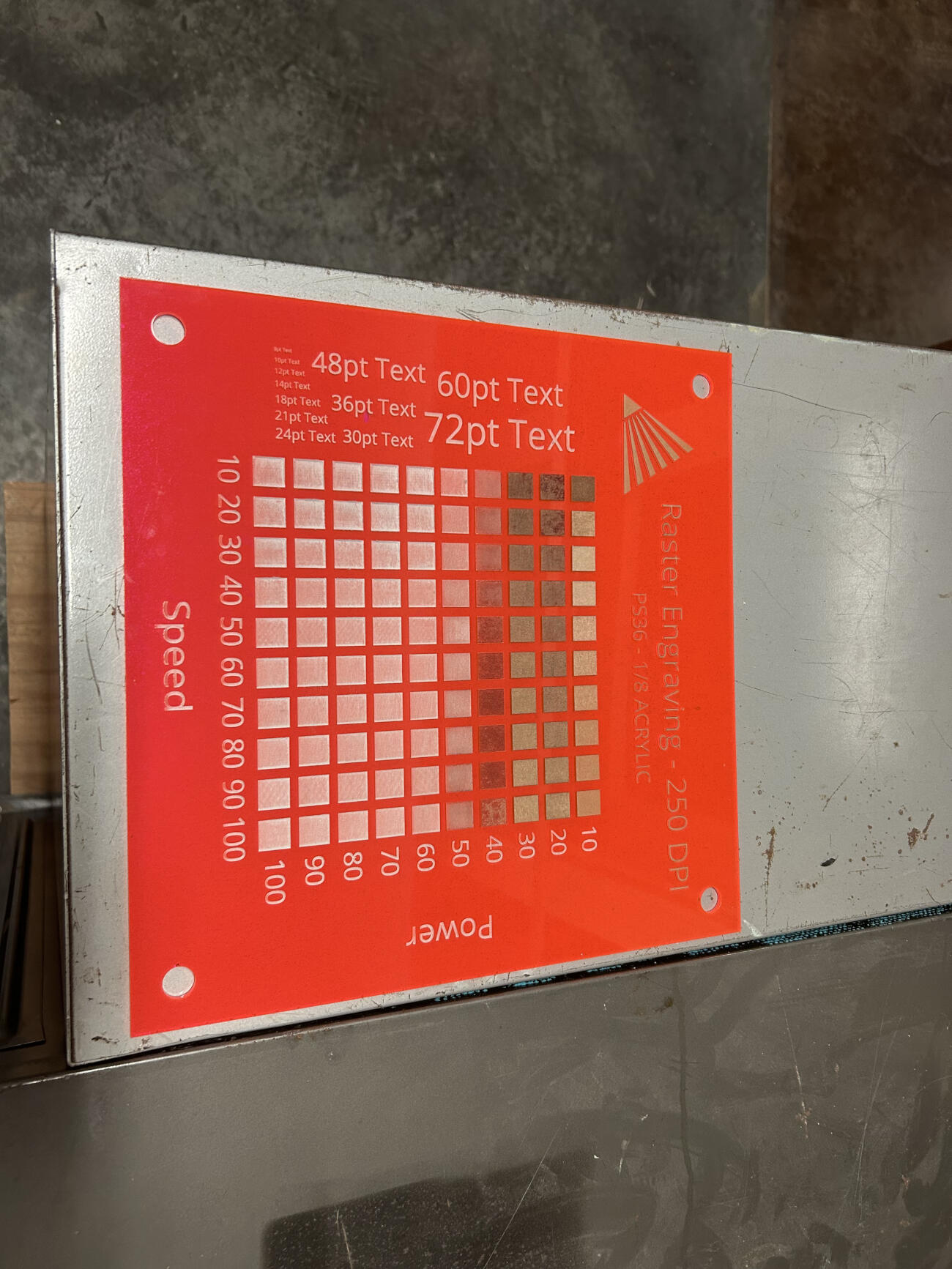
Once our focus was in order, we set about shifting our attention towards power and speed which was rather easy thanks to Full Spectrum Lasers, the manufacturer of our laser cutters, vector and raster tests available on their website. We were not satisfied with the tests as they were especially since they were rather small and easy to lose so we chose to modify them. The modifications to their templates included a resizing, making each 12"x12", the addition of holes in each of the four corners, this is for display so members can see what works, and the addition of fonts on the left side of the template, so anyone can see what font sizes are readable and which aren't.
Laser Kerf
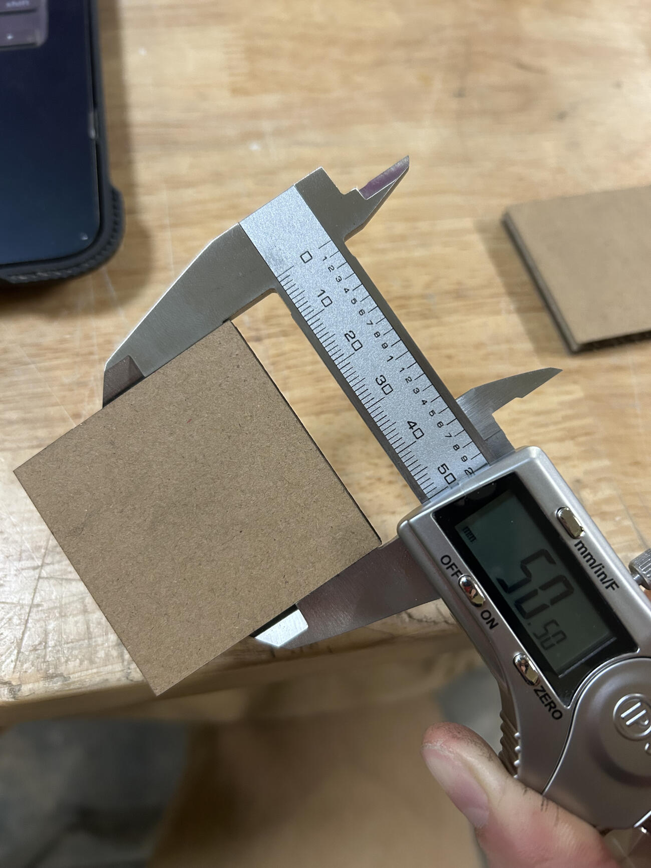
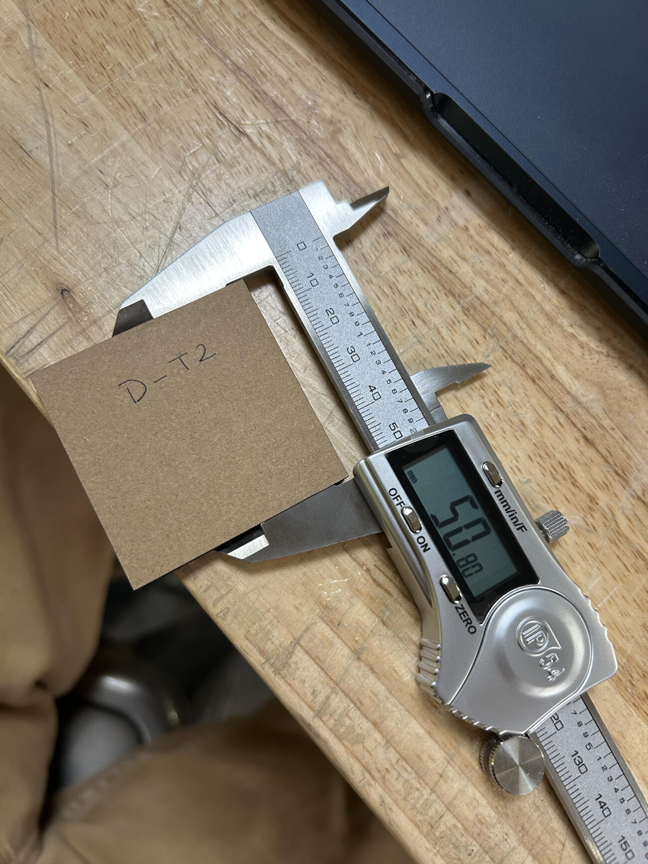
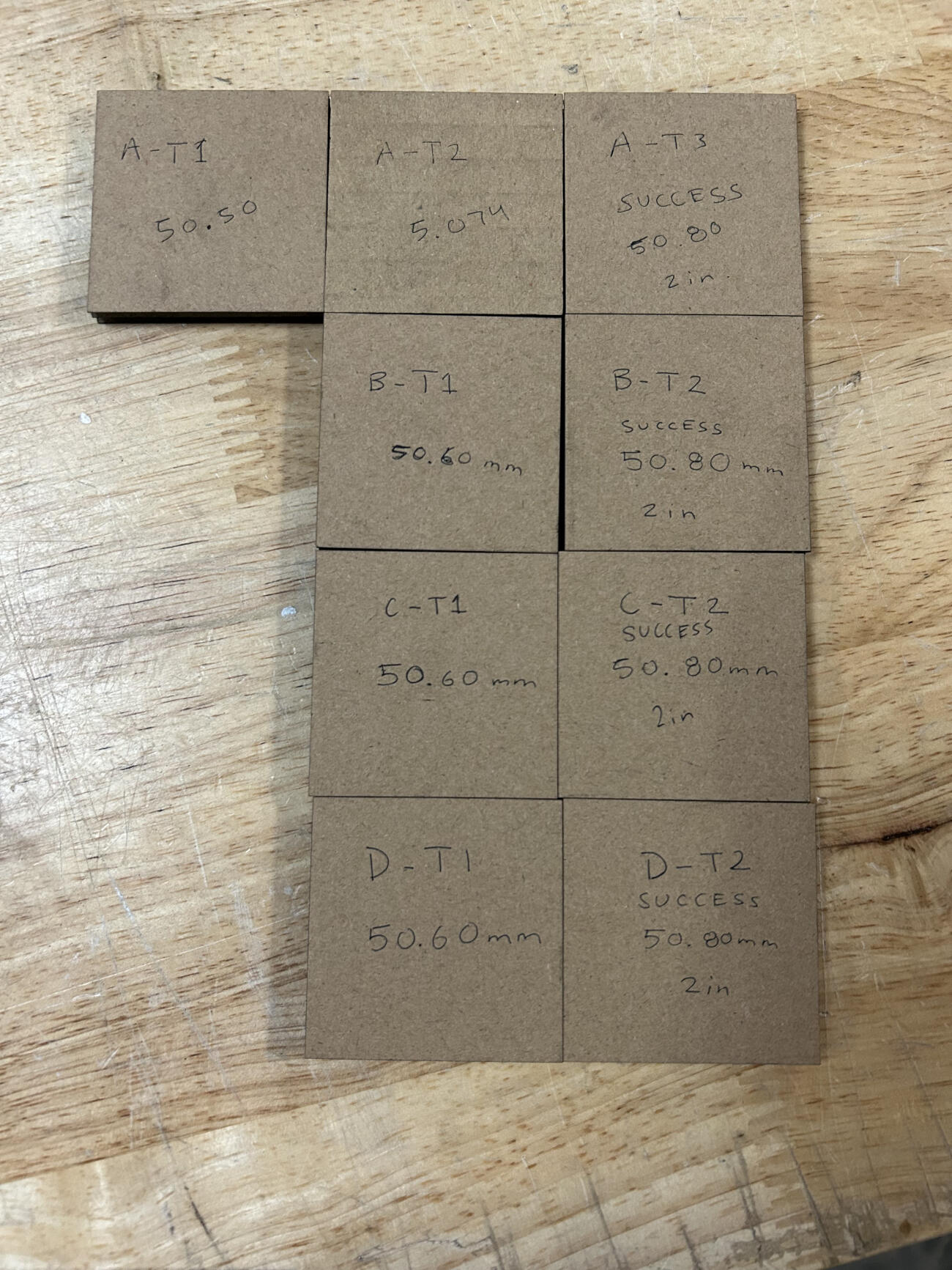
We set out to cut 2 in. (50.8mm) squares in 1/4 cardboard and using a caliper for extra precise measurement we found out that our first cut was off from 50.8mm exact by a bit. We tweaked it further by increasing the size of the square by .14mm and realized we were still short so we increased it by .06mm. This third run allowed us to physically get 50.8mm with our cuts but digitally we had to program the square to be 51mm in both length and width. The odd thing we noted after is that even though we had noticed a 0.20mm difference in the kerf, after measuring our first run again we realized it came up to 50.5mm and our last run was what we needed at 50.8mm. We concluded that our inconsistent power and passes settings may have altered the results so we did three more rounds of testing at 100 speed, 60 power, and 1 pass. Each consecutive set of tests were simpler now that we knew the overall offset of 0.20mm and each test was able to successfully get to 50.8mm physically while keeping the 51mm measurement digitally. In conclusion, the offset we have to take into consideration is 0.10mm for each line cut if we want to get perfect and precise sizes and measurements for any future cuts.
Joint Clearance and Types
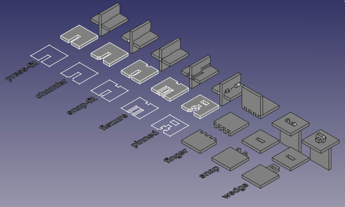
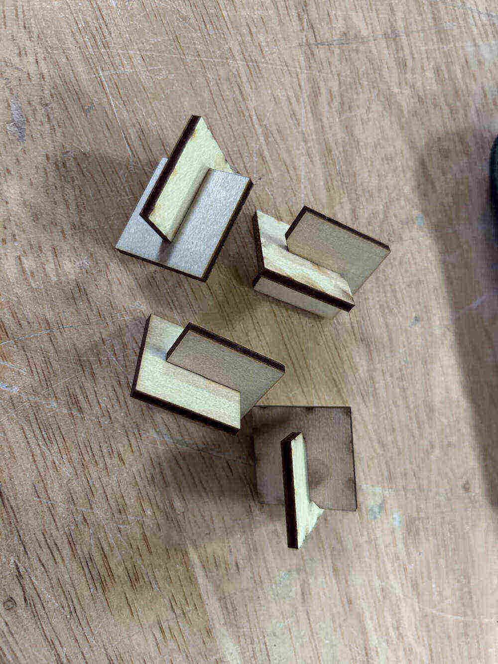
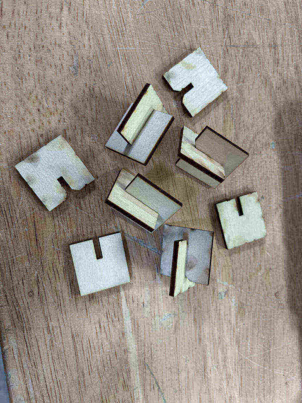
Both of our projects utilize simple joints. We resorted to press-fit and chamfered and that is what we cut and tested. Both worked for what we had but we noted minimal differences between each as they are both essentially press-fit, the only difference being that the chamfers for the chamfered joint serve as a funnel that slides any connections into place. We did take note of the various different types of joints one can cut below.
Press-Fit - The most basic joint. Thin slot on any surface that slides in together.
Chamfered - Just like the press-fit except the chamfers serve as guides or funnels that make it easier to fit connections into one another.
Snap-Fit - Snap fit cuts a box at the bottom of your piece and incorporates prongs into the slot. When two of these pieces slide in together, the prongs snap into the boxes both have at the bottom making for a snug fit.
Flexure - Flexure incorporates prongs with curved heads and spacers on the sides to allow for some flexibility in the prongs. Like the snap-fit, there are boxes at the bottom of the joint so that when two join together the curved heads on the prongs snap into place there.
Pinned - The pinned joint slides together very simply like the other joints do, but there are gaps in the pinned joint that then allow you to drive a pin into it perpendicularly.
Finger - Snug joints if kerf is accounted for properly. Very useful for making corners and building walls.
Snap - They utilize prongs with curved heads at the top of their stems that slide into a slot. The curved heads also serve as hooks because of their flat underside. The prongs are cut in a manner that allows for some flexibility but not enough to move on its own once locked into place.
Wedge - Three part system. Wedge goes into slot, wedge has a hole that has a pin placed in it to lock wedge into place preventing movement.
WEEK 12 - Mechanical/Machine Design Week
Since we both plan on having moving components utilizing motors in our final projects, we wanted our machine design for this week to have some overlapping features. After deliberating, we decided to make an automaton.
You can see our individual documentation on our own websites linked below -
Vicky's Week 12 Assignment Page
Augusto's Week 12 Assignment Page
Below is our one minute video showing a brief overview of the entire process.
Reference/Research
We both did some research and looked to Stoccafisso; a well known automata maker; for reference and inspiration. While his work tends to be more hand carved and highlights the simplicity in the mechanics of his design, we wanted to get a little more technical with the design and function of the mechanics.
As far as subject matter, after rolling around a couple of ideas we landed on creating a dragon that would flap its wings when triggered by a motion sensor. We both are into fantasy, the arts, and films and both of our fab labs host camps/classes for kids. This could be a great project to teach kids about animation, film making, and animatronics.
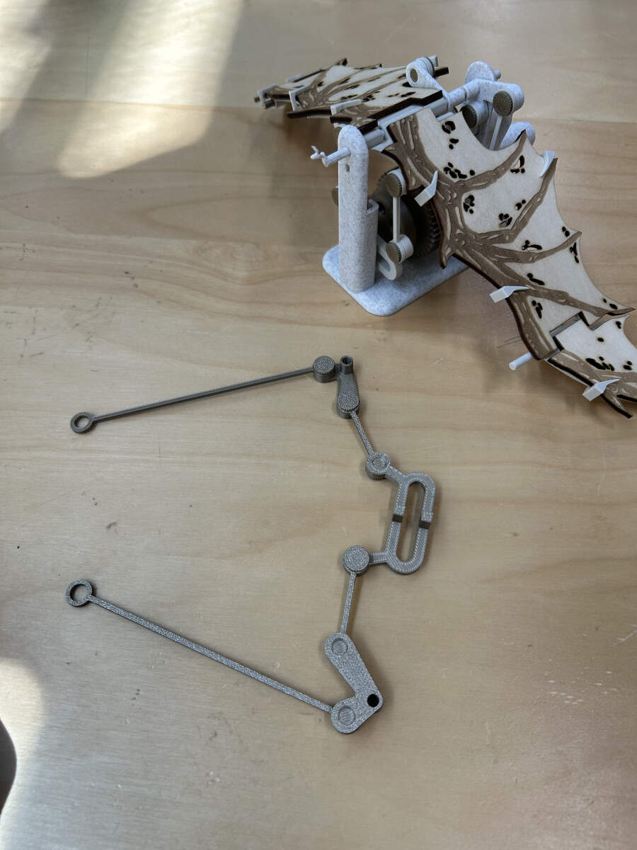
To get our bearings and figure out how to actually construct our machine, we looked for a template on instructables to print a test sample. Together, we found a sample that had flapping wings and immediately went to print this file. Link and image below.
https://www.instructables.com/Pterodactyl-Pseudo-Style/
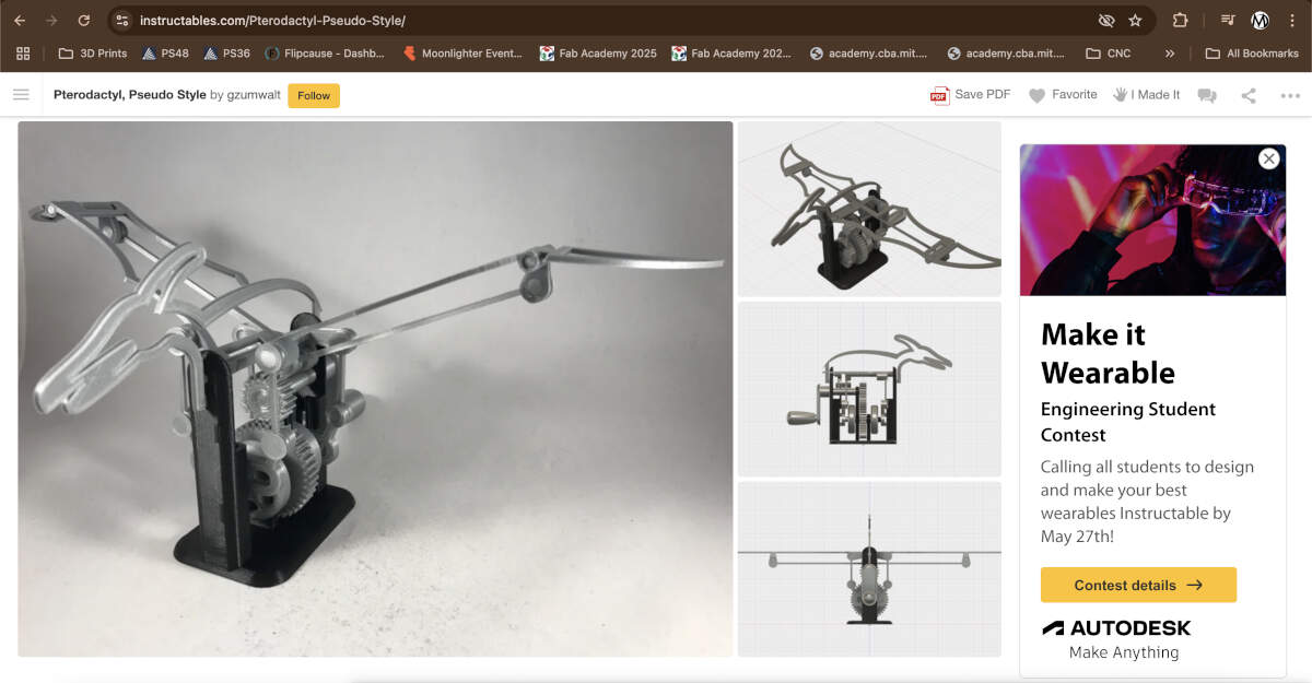
After sending the sample file to print, we constructed it together and started to get a better understanding of the mechanical components and construction.
Redesign
With our sample automata assembled and functional, we jumped to designing our take of a dragon automaton.
While we already knew we would be using a 360 degree motor for our machine, it was nice practice to get a feel of the motion and speed with a hand crank. We created a basic plan on how to change the gears and components to become fully automated and more fitting for our end goal.
Electrical Components - Coding
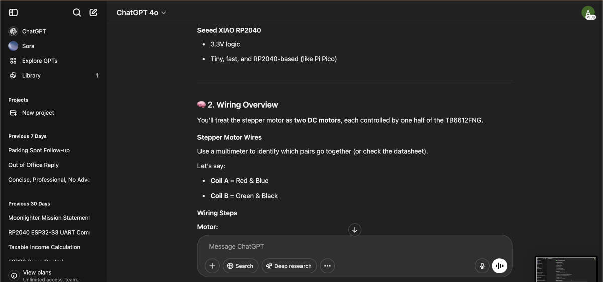
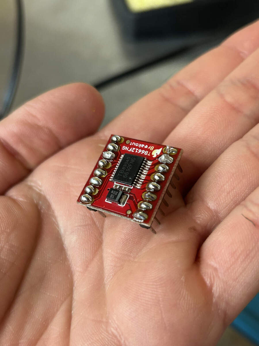
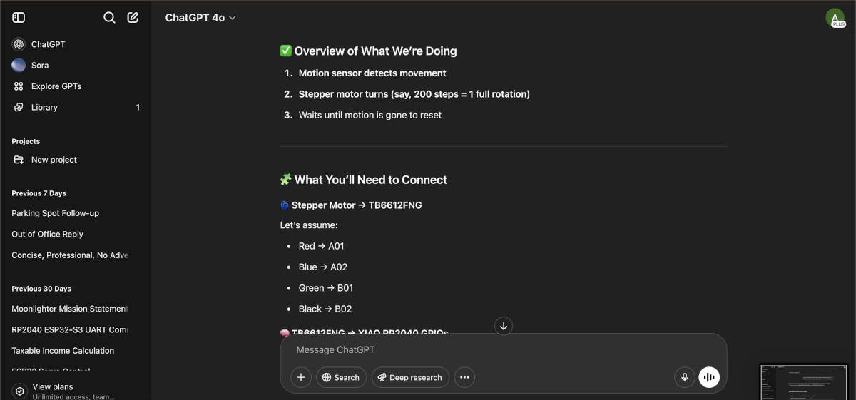
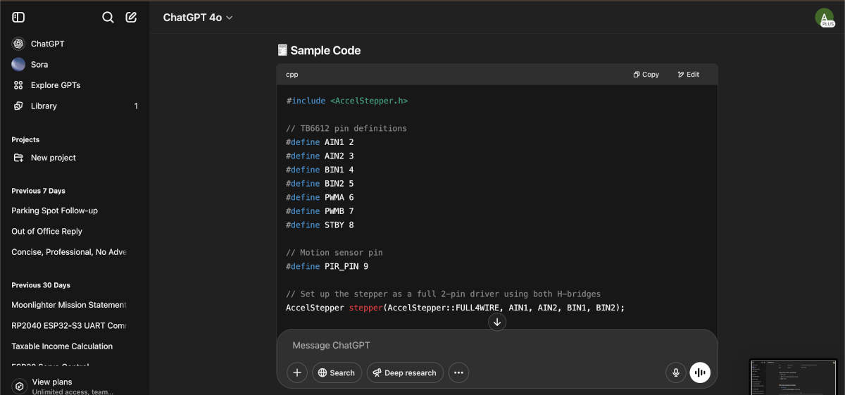
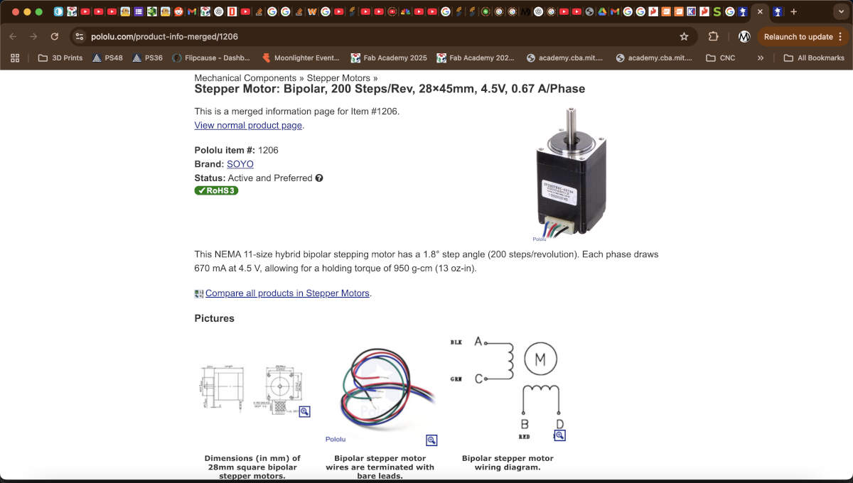
We chose to use an RP2040 to control a stepper motor with a motion sensor. One of our instructors, Peter, saved us lots of future hassle by informing us, we would need a motor driver to help control the stepper motor we chose to use.
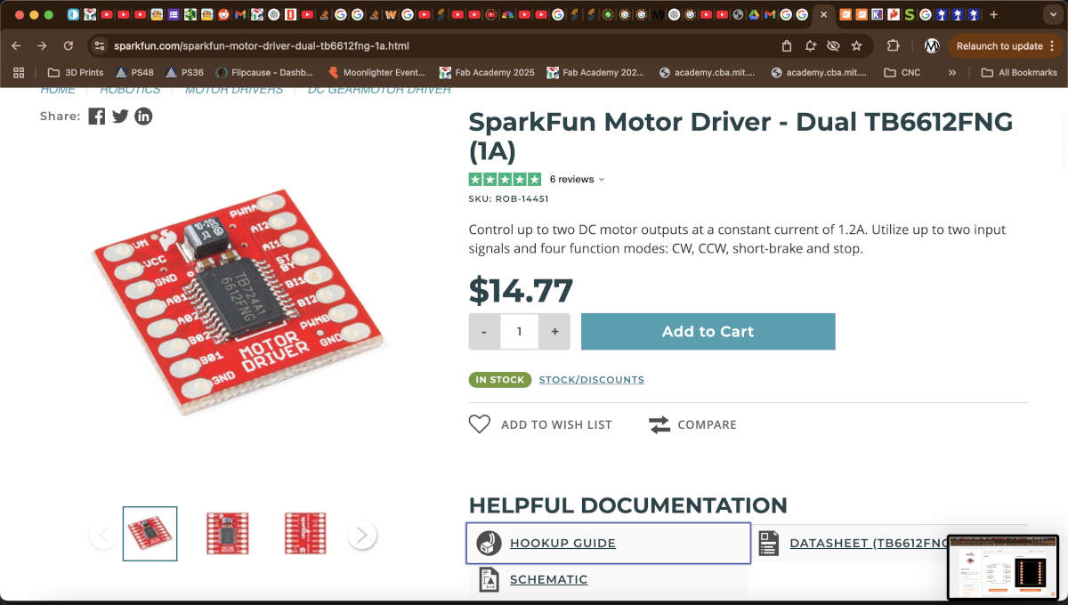
A motor driver takes pulses from the controller and converts them into the correct voltage and current levels to energize the coils, required for a stepper motor to operate. It also helps protect the controller from too much current or voltage spikes that can damage the controller's output pins.
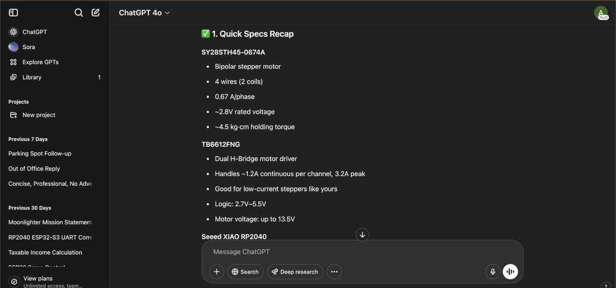
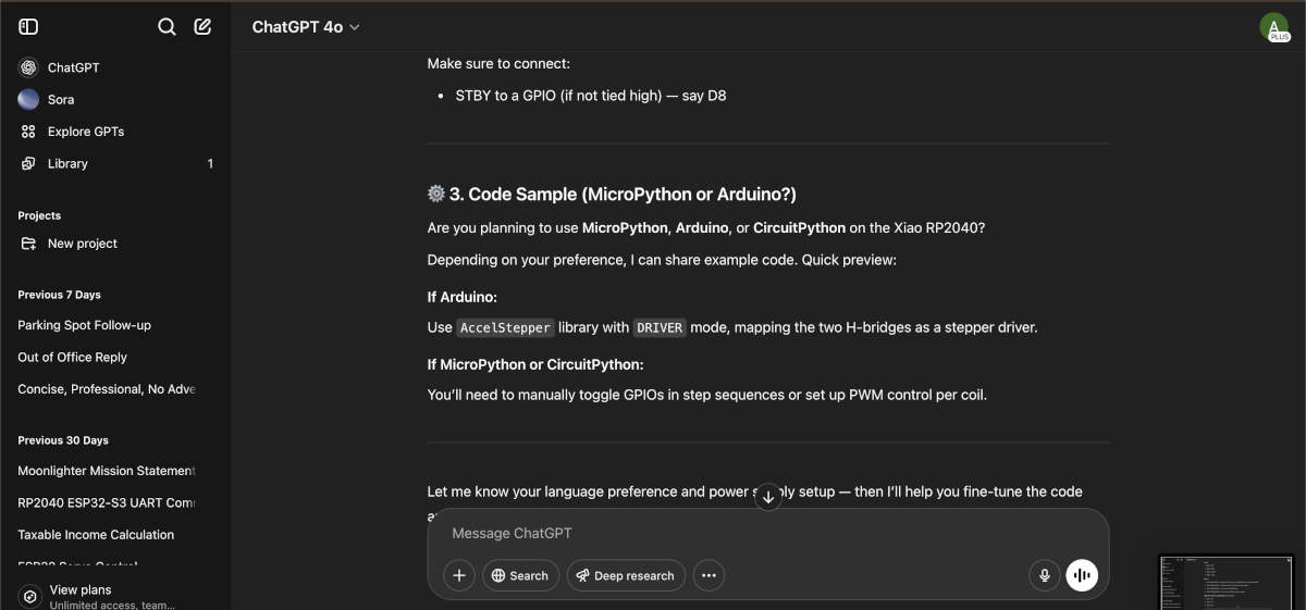
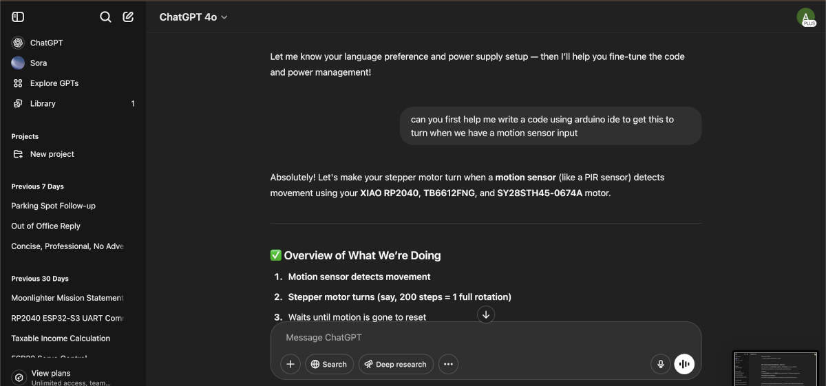
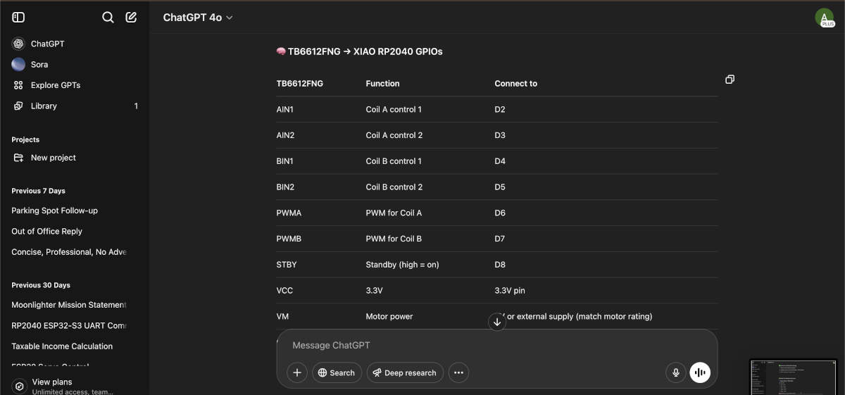
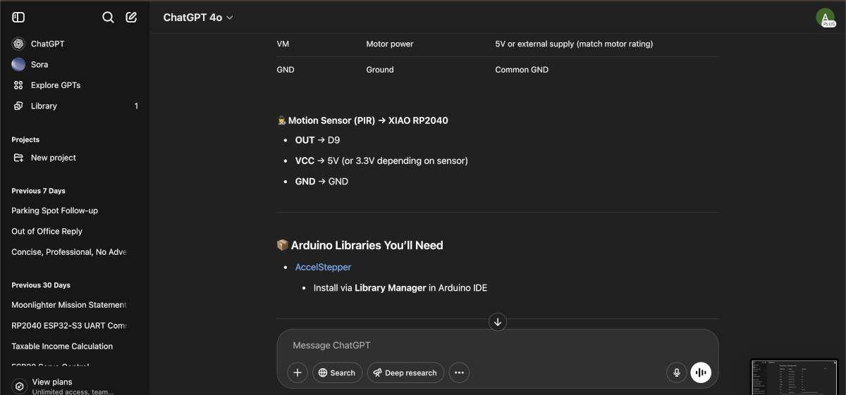
Thankfully we had assistance from ChatGPT and Peter to get our connections and code formulated and up and running. Chat went into detail about what connected to what and where.
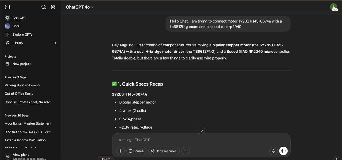
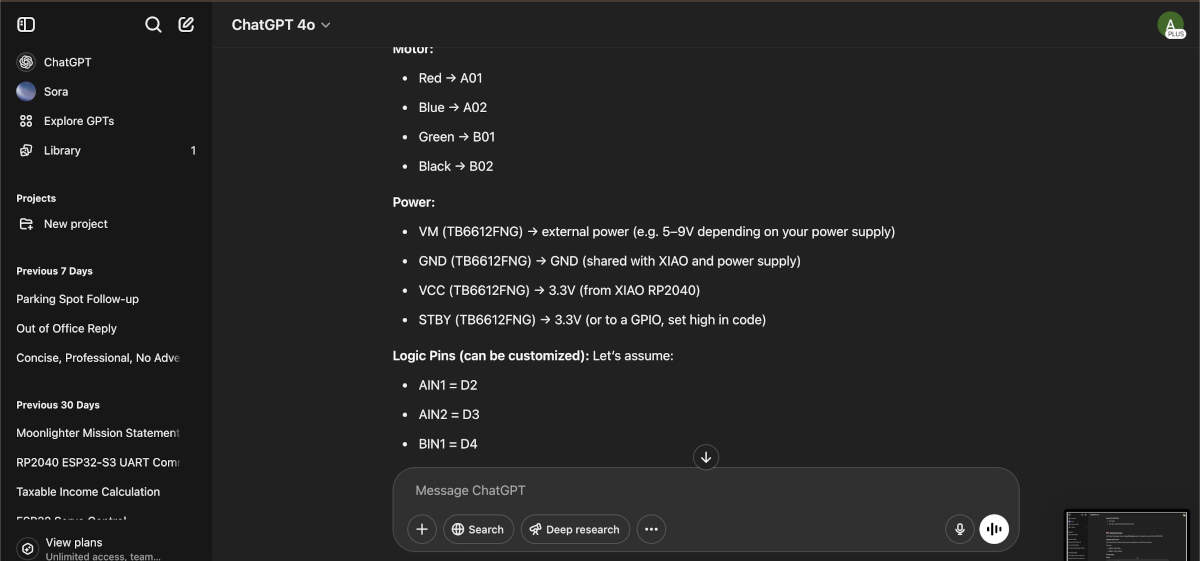
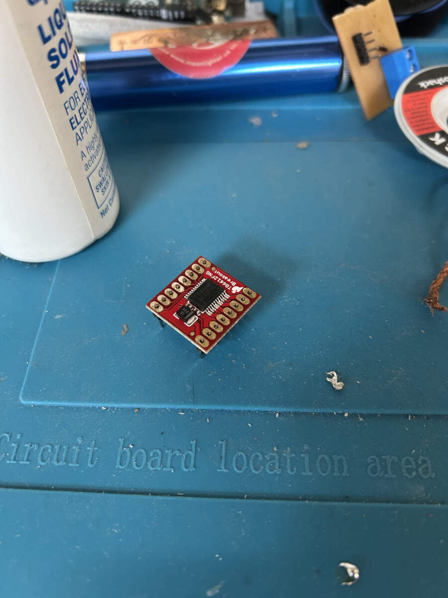
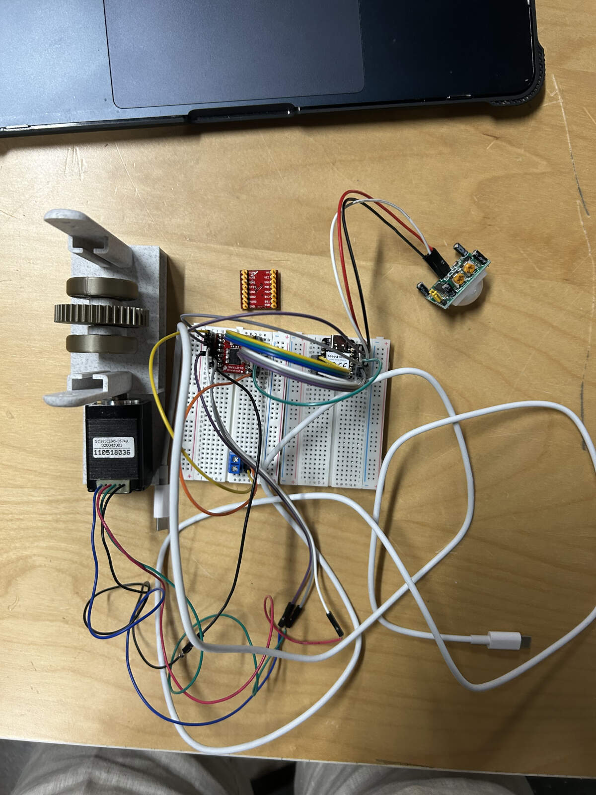
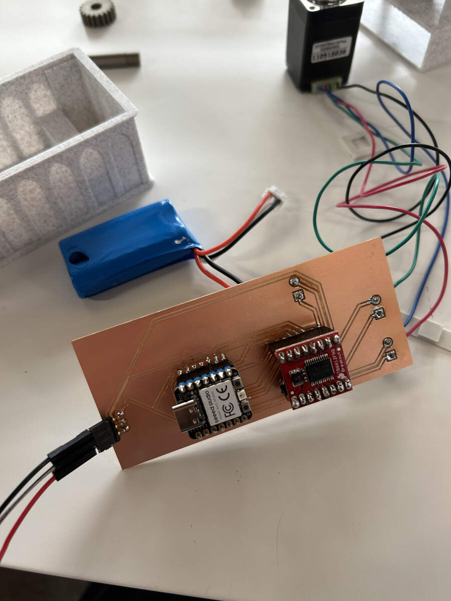
With this new knowledge, we wanted to continue learning together how it works and test coding using breadboards. Augusto got to soldering the Motor Driver while Vicky soldered the RP2040. Once the soldering was done the driver and microcontroller were put in place and connected using the information we had gathered from our ChatGPT log.
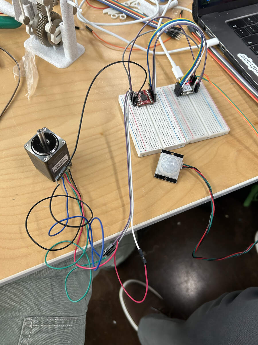
With everything put together, Peter helped us develop a quick set of code to test the PIR sensor and see if it was functioning properly and to hopefully get a better idea of its sensitivity range. To do so, we added in a serial monitor to have a read out creepily inform us when the sensor could “see us” or “see nothing”. The Motion sensor works! A bit finicky and sensitive but working.
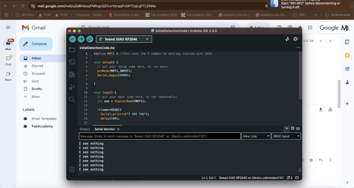
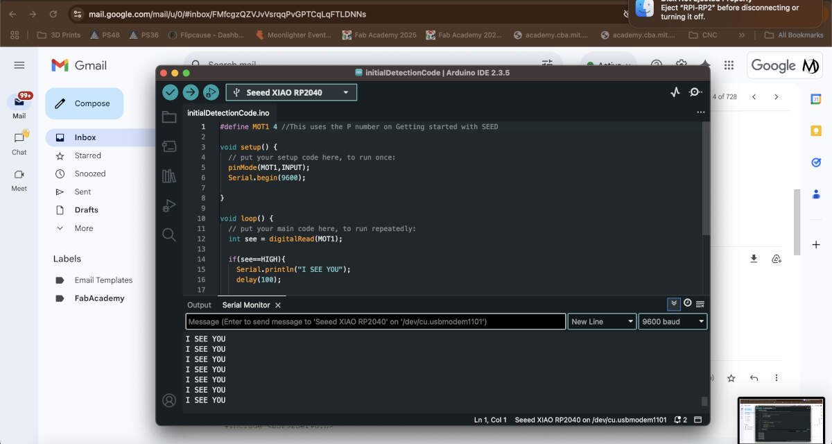
Include initialdetectioncode.ino here
Seeing how this code worked with our setup we went back to ChatGPT and asked it to write code using the motion sensor as an input and output into the stepper motor. We soon tested this code and found that it worked perfectly. The stepper motor would rotate every time the sensor picked up on movement. ChatGPT log and code located below. With our inputs and outputs functional and code working, we felt more comfortable with our project development and began to divide and conquer.
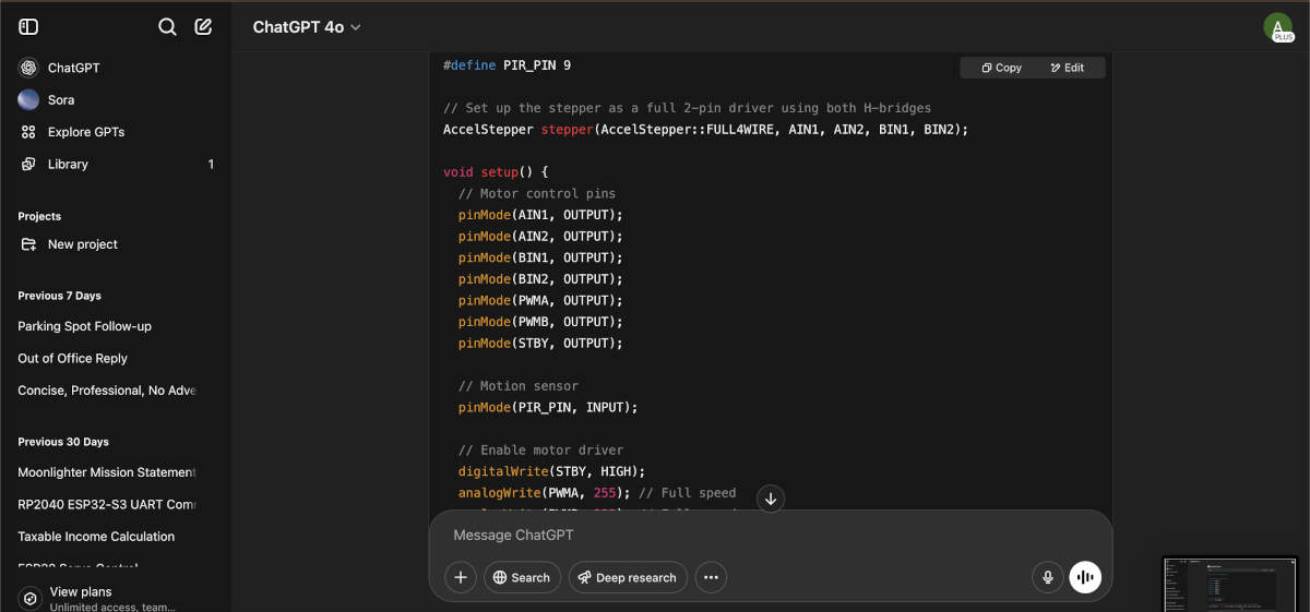
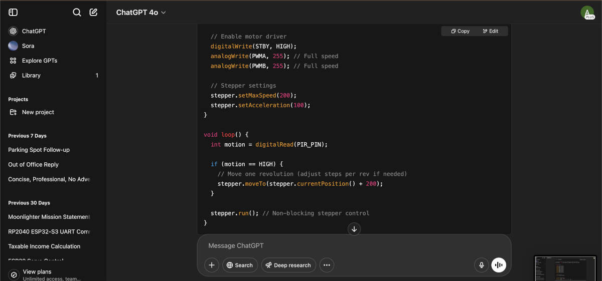
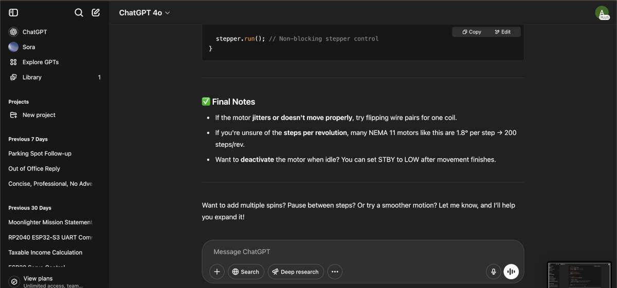
Include “finalmovementcode.ino” here
Electrical Components - PCB Board Design and Milling Process
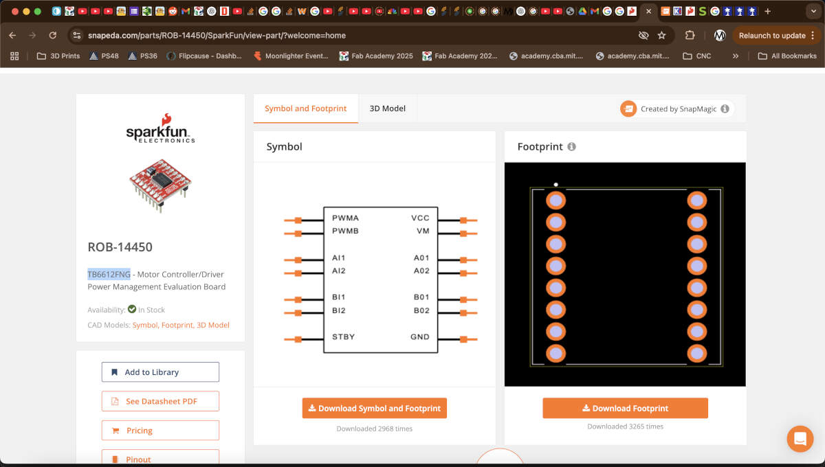
Already having gone over the connections with Vicky, Augusto got to work designing the PCB board on KiCad. The first step to complete was locating a footprint for the motor driver online. Thankfully SnapEDA had both the symbol and footprint on their website.
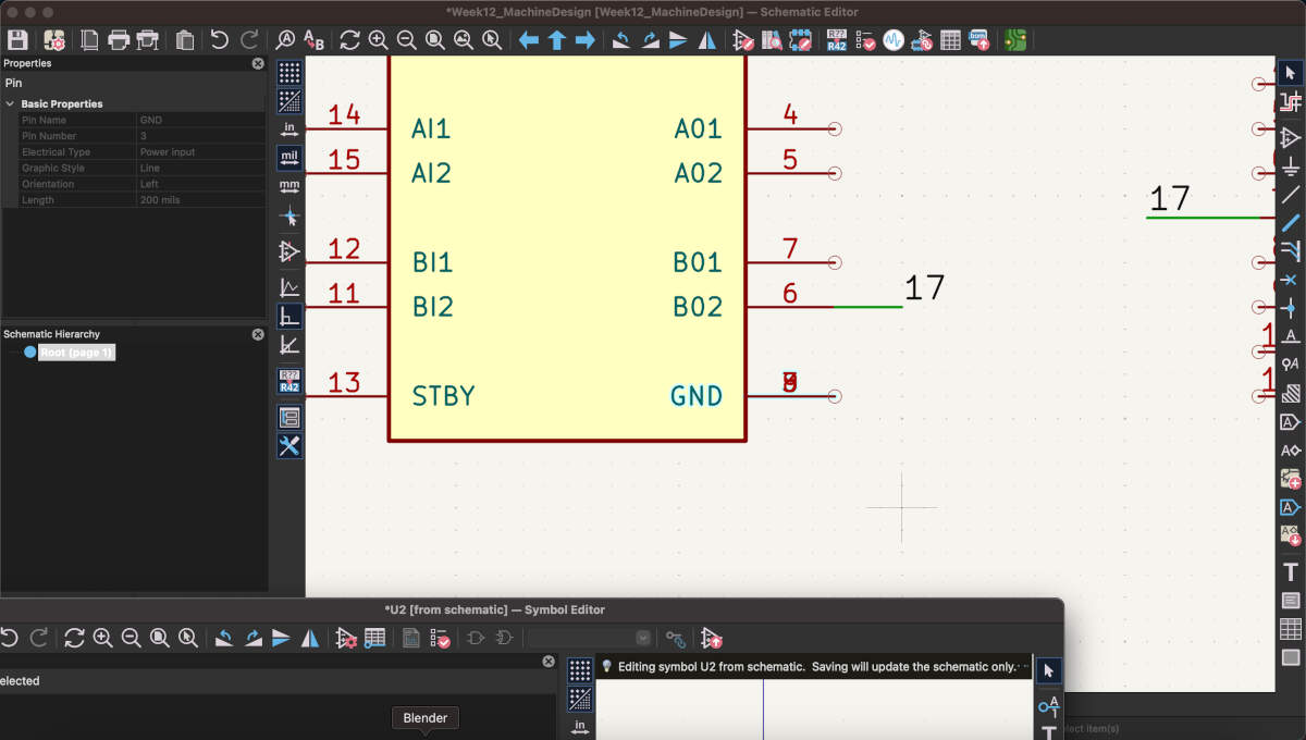
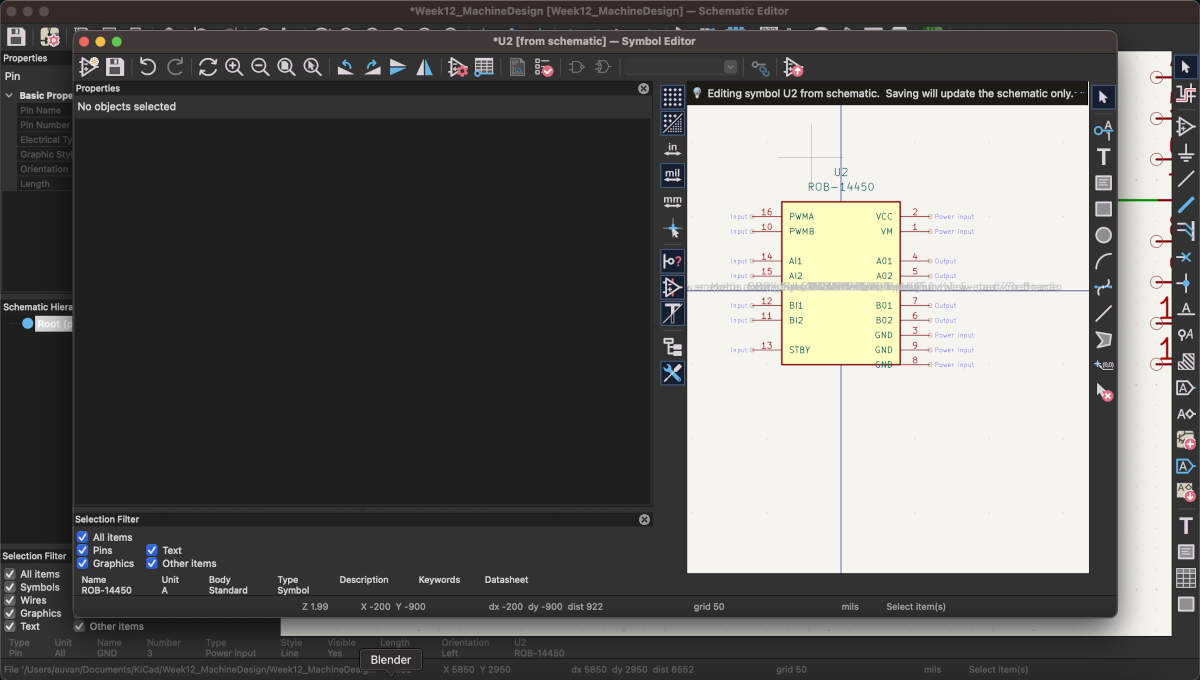
Unfortunately for Augusto, the symbol for the schematic portion of the design needed editing because 3 of the pins were overlapping each other.Augusto was able to move those three pins away from each other so that they could be read and connected to other parts of the board.
The schematic portion was finalized using a heavy amount of tags to signify what was connected to what otherwise it would have been too much visual clutter.
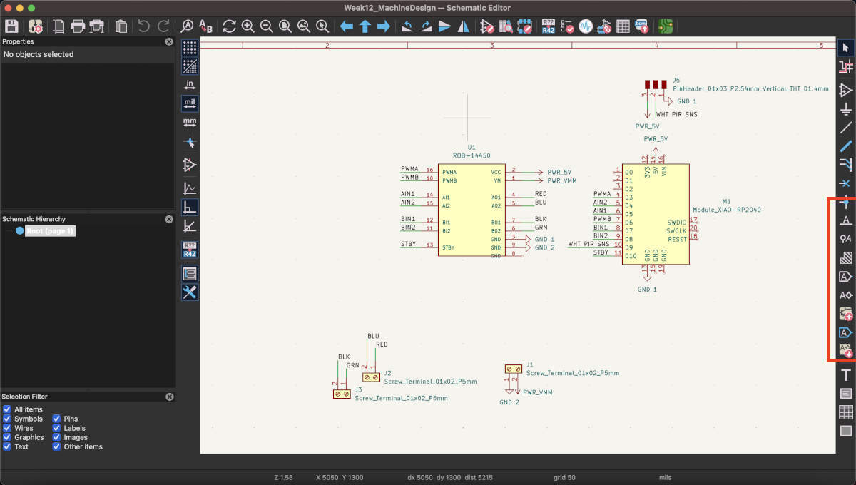
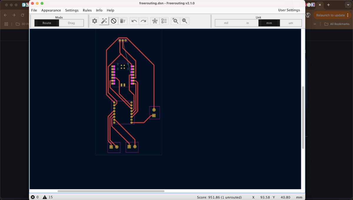
Augusto proceeded to lay out the footprints/components in a linear fashion that made sense for the soon-to-be redesigned model. One end would connect to the PIR sensor with the microcontroller being closest to it , the other end connected to the stepper motor which lead directly to the motor driver as suggested by the earlier mentioned ChatGPT log. To save on time, Augusto tried FreeRouter for the first time and was able to generate a perfect set of paths for the board after generating a few different designs/seeds.

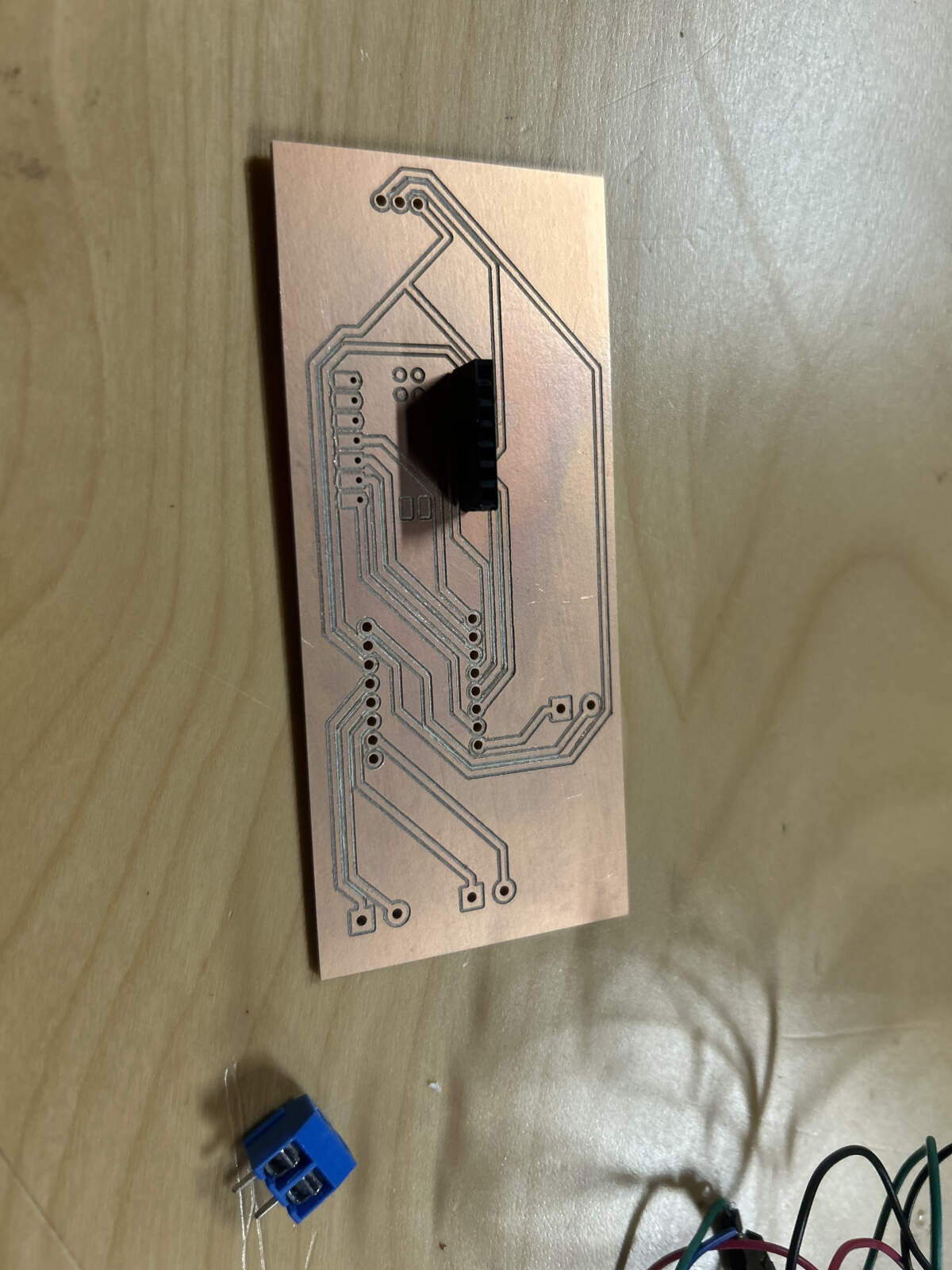
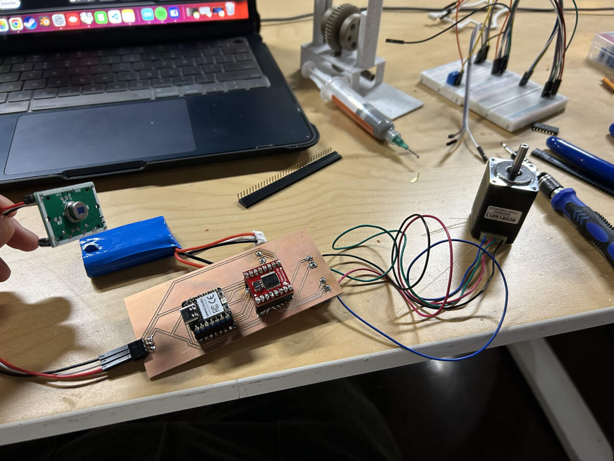
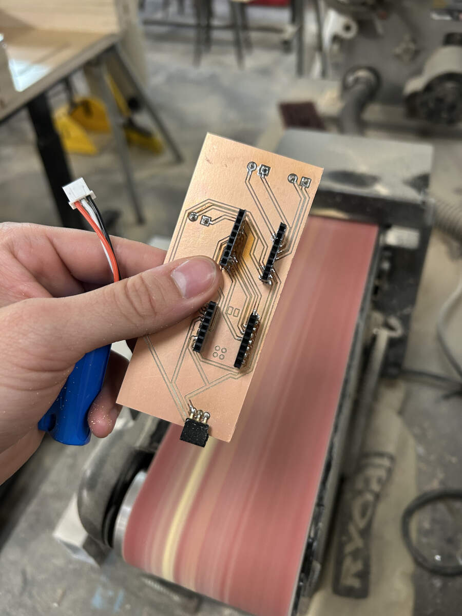
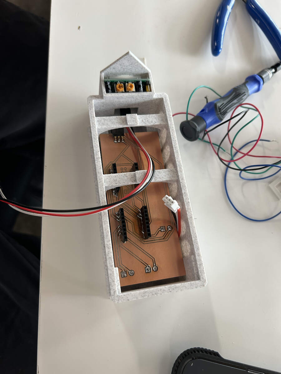
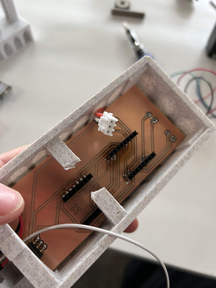
Once Augusto finished the PCB board design, he sent the files over to Vicky who proceeded to mill the board. Once milled, Vicky started to solder the pin headers to the board to make it easier to test and switch out microcontrollers, inputs and outputs if needed. Augusto finished soldering the connections for the additional power, inputs and outputs.
2D and 3D Design - Vicky's Portion
Vicky worked on the design of the dragon to incorporate laser cut components and redesign the 3D form, while Augusto worked on designing the base enclosure and redesign mechanisms.
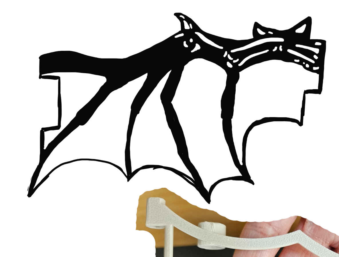
To start drawing out the wings, Vicky first took pictures of each 3D printed section to make sure when sketching the new design, she kept in mind the shapes and proportions needed for connecting one another in a functional manner.
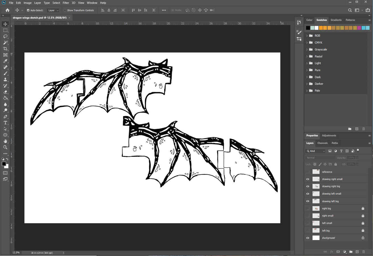
She drew out the designs in Photoshop using a tablet and then moved them into Illustrator to turn the drawings into vector files and clean up any linework. This was followed by separating raster and vector cutting layers.
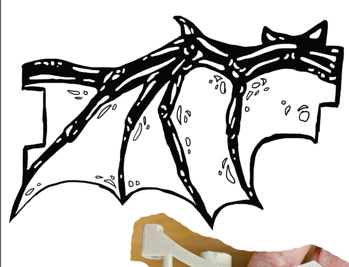
Before cutting the wings out of wood, Vicky ran a test outline cut out of paper. Even though it seemed pretty close, there were a few areas with slight misalignments that could cause problems when in motion. She should have known better than to use a photo of a part to draw components with accuracy.
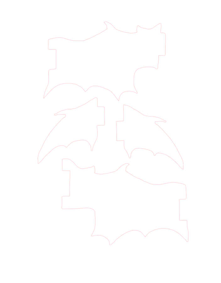
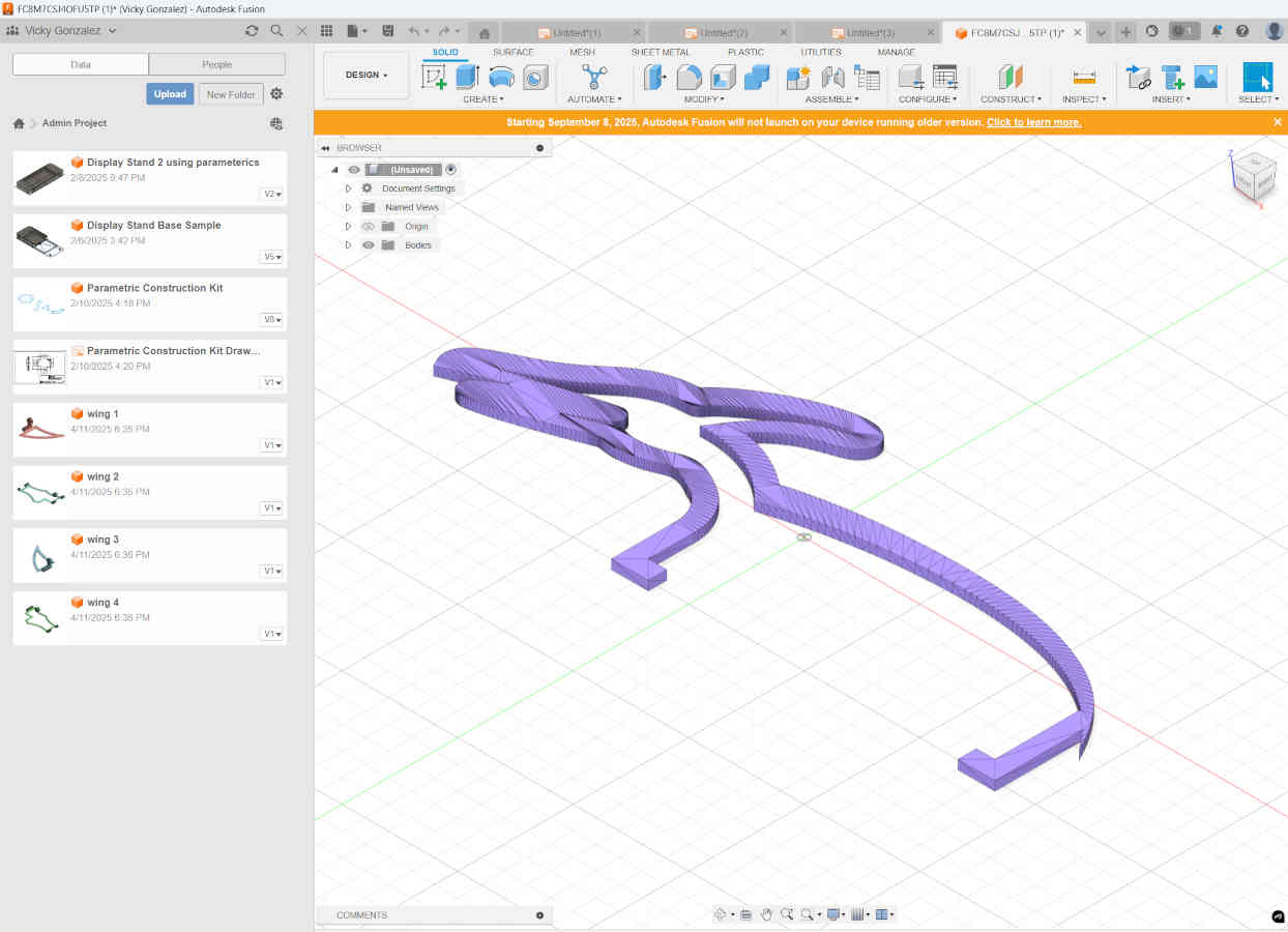
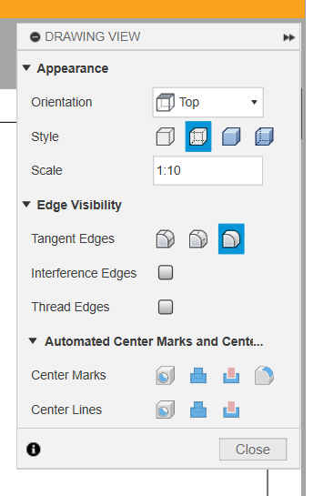
To fix the minor inconsistencies and get more accurate measurements. She used the 3D files and converted them into 2D files, making sure each piece was converted in the same scale, to then match up the drawings accordingly.
With the first run of the wings in wood, they looked pretty good, aligned properly when still. There was a slight tolerance issue when in motion though, that prevented the wings from moving their full range.
A few trims and a couple file tweaks later, the wings were good to go.
Vicky Drawing Needed Here
The body of the dragon was created in the same fashion as the wings but with less constraints to worry about since it was going to be one solid non-motion piece. The body took some time design wise to make sure it actually looked like a dragon and not some derpy snake lizard.
To attach the laser cut pieces to the model, Vicky designed clips as an additional design element that would hold the wings in place. These made it easy to remove if the model needed to be worked on and reapplied or to change out the designs to something different all together, like many stop motion companies do with their character structures in various manners.
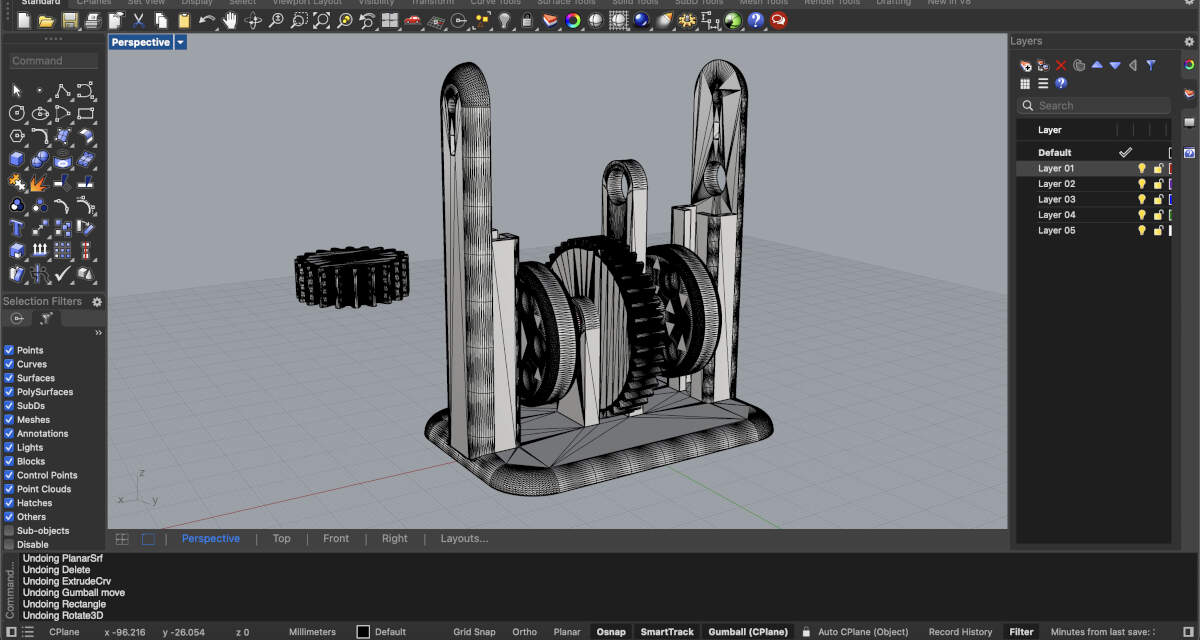
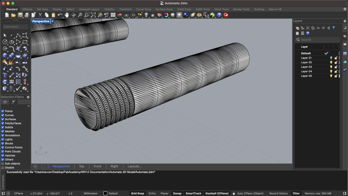
2D and 3D Design - Augusto's Portion
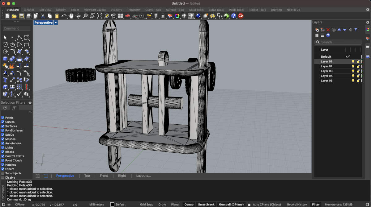
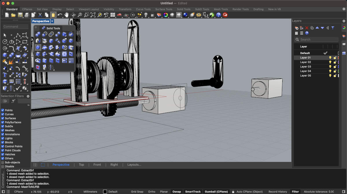
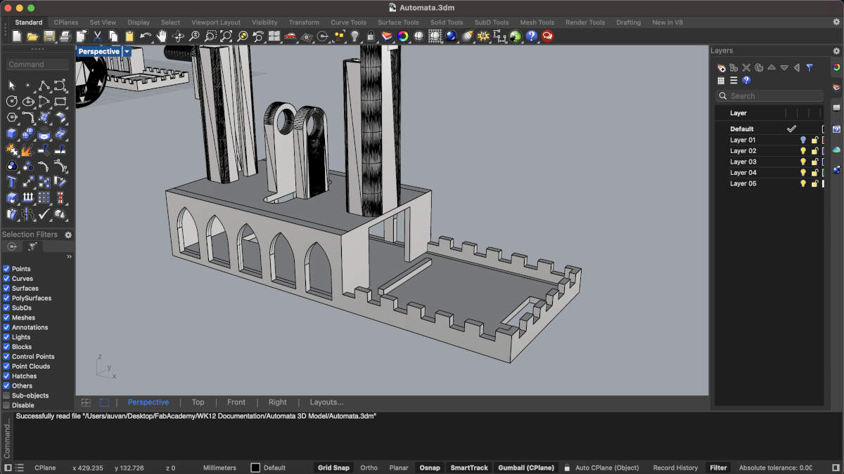
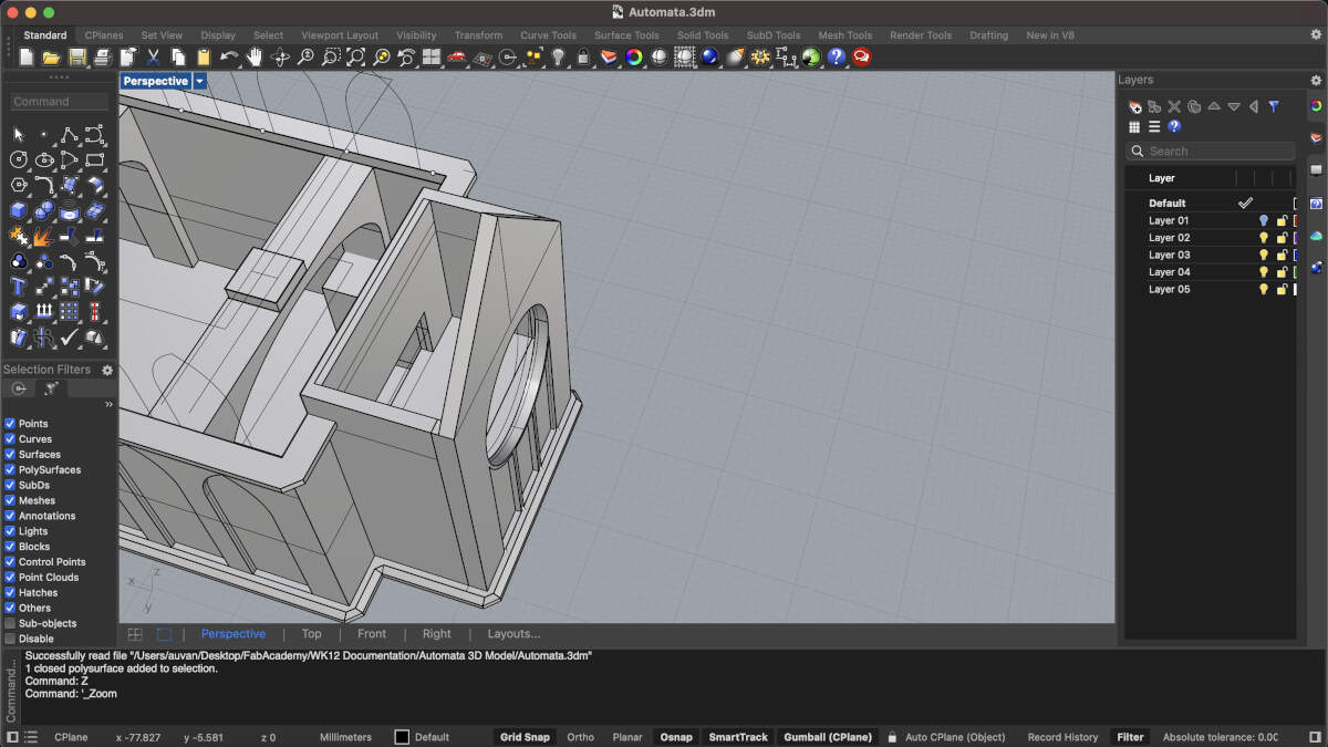
To redesign the base and mechanism of the automata, Augusto decided to import the most relevant aspects of the model into Rhino3D. With the relevant pieces on display it became easier to see how Augusto could alter the model. To redesign the mechanism we essentially had to flip it so that the smallest gear responsible for moving the rest was underneath the base but still in contact with the other gears. To ensure this gear would always have the same function, the entire base was copied and flipped on its head using the holes holding all the big gears in line as a central rotating axis. That way the smallest gear would have the same distance it has on top as it would then have on the bottom.
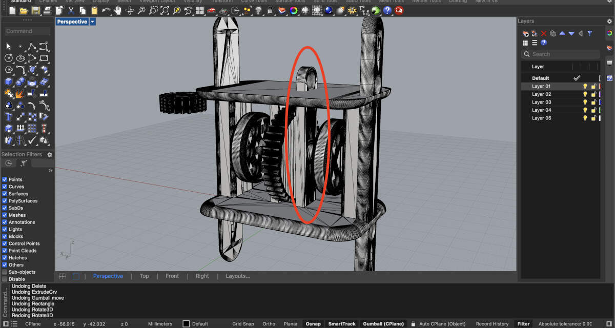
This circled piece is the affected, edited, and mirrored bit of the model.
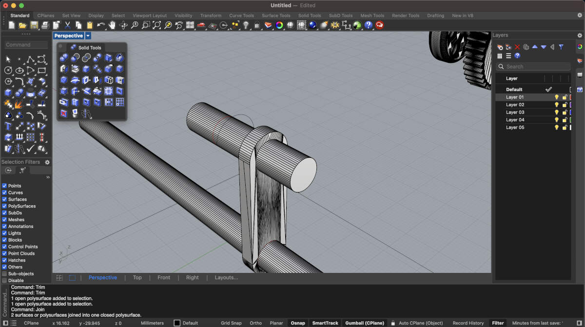
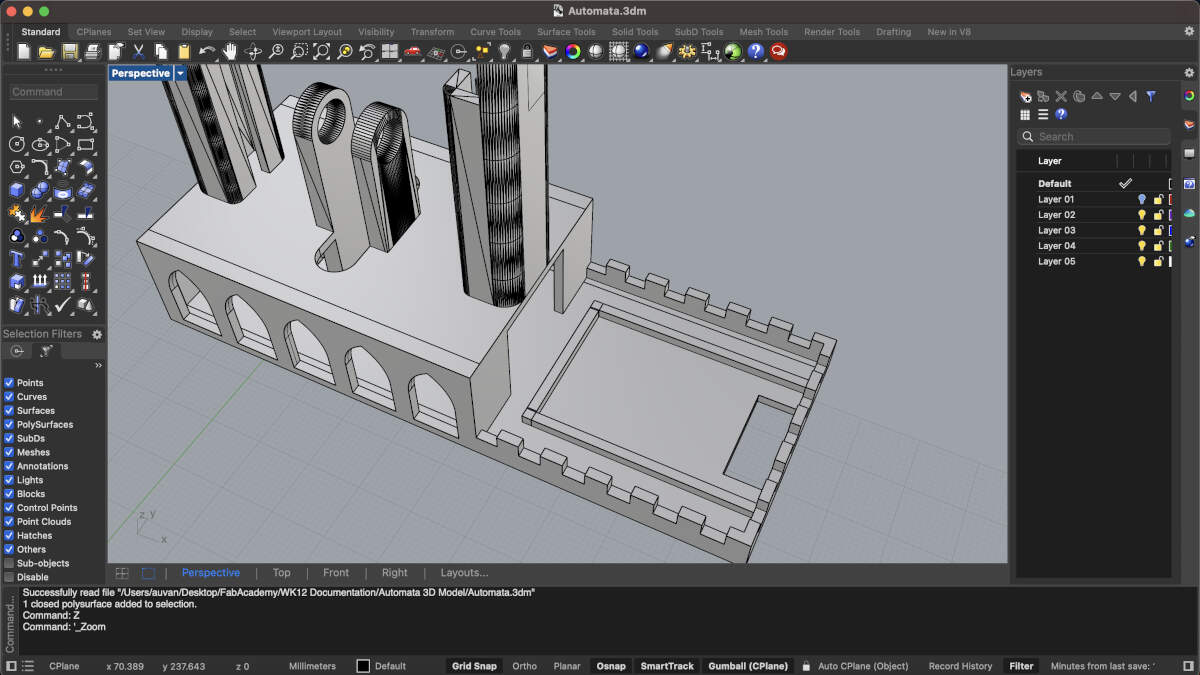
The rod here displays using that portion of the model where the gears were formerly at as the central rotating axis.
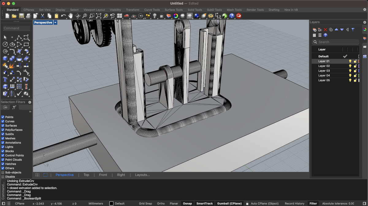
The base is being reduced to accommodate the smaller gear that will now be located at the bottom.
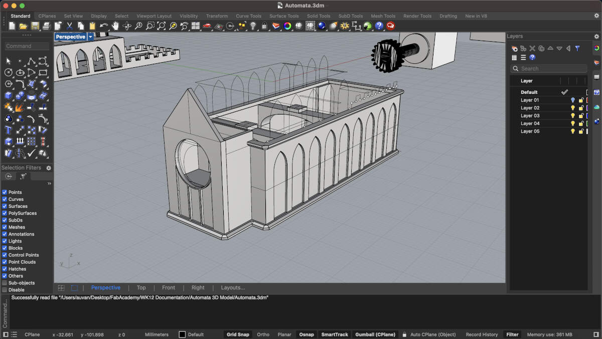
This is the end result for the flipped piece.
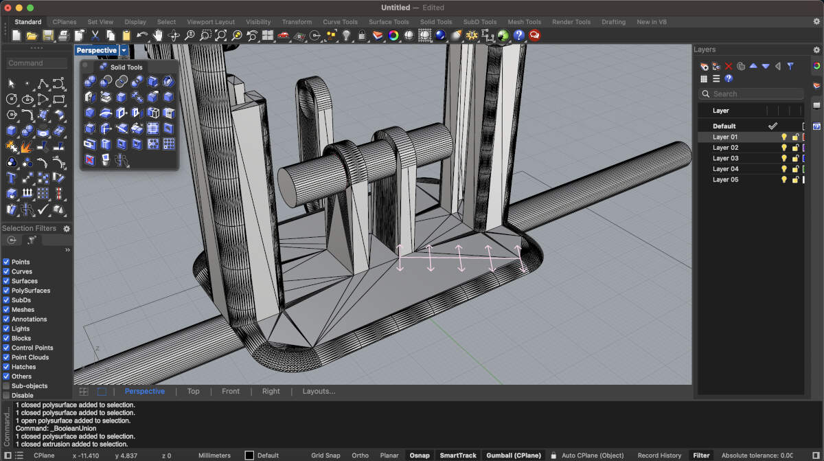
This altered version of the base is nearly complete.
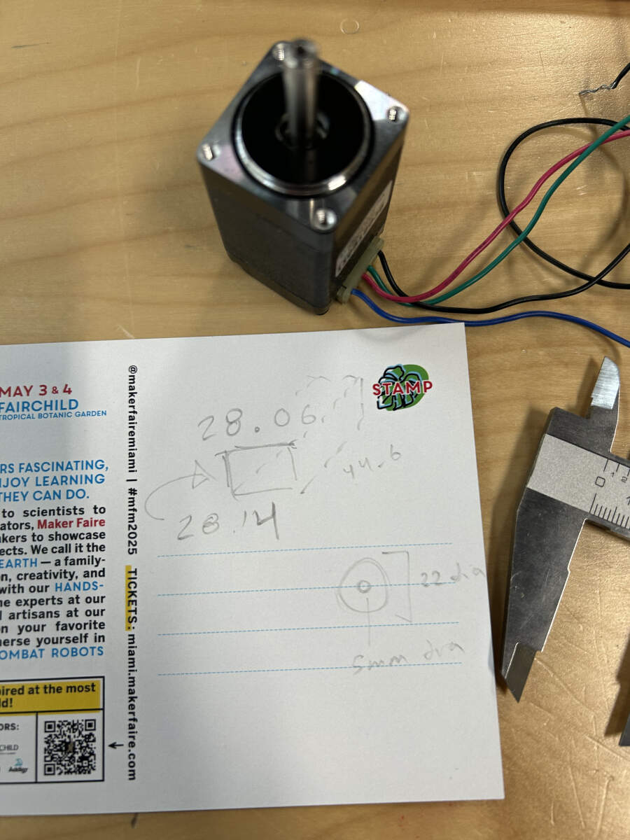
The stepper motor chosen was measured using a pair of calipers.
With its dimensions established a digital copy was made to easily visualize its place in the model.
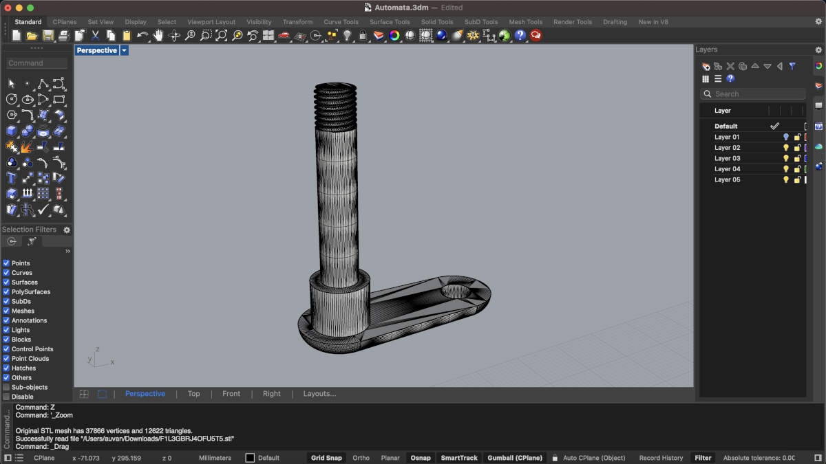
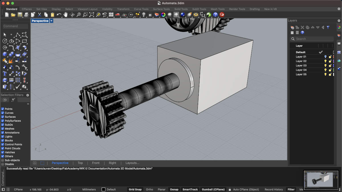
We altered the original handle and modified it so that it could be press-fit onto the stepper motor. The handle’s screw was sliced off, hollowed out using an internal extrusion and then slid onto our motor. Playing with the tolerances was a must given that our first few prints did not fit onto the motor but at least it worked in some sense.
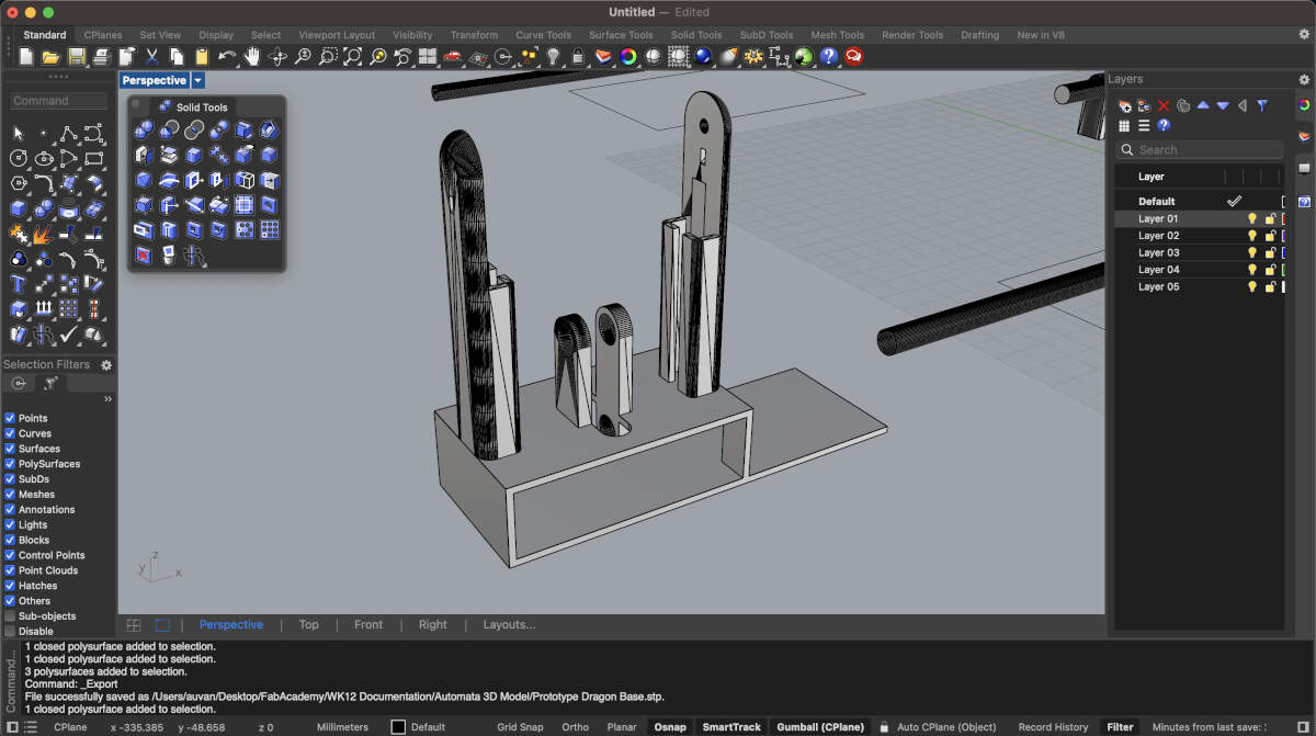
With the mechanism modified, I quickly put together an easy first draft or prototype of the base to test the modified mechanism with the stepper motor. With our connections and electronics already having worked it was no surprise seeing it work perfect with the modified base/mechanism. From that point forward it was easy to create the rest of the model.
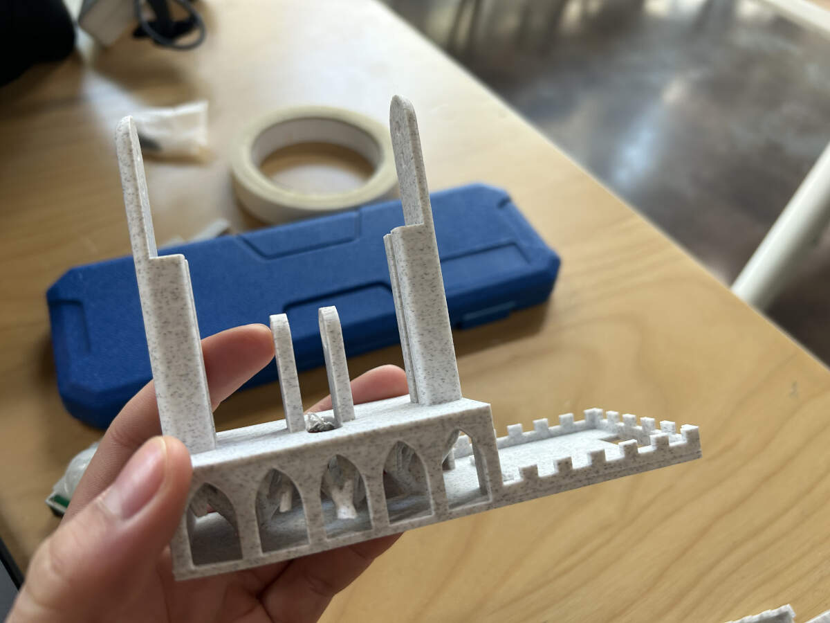
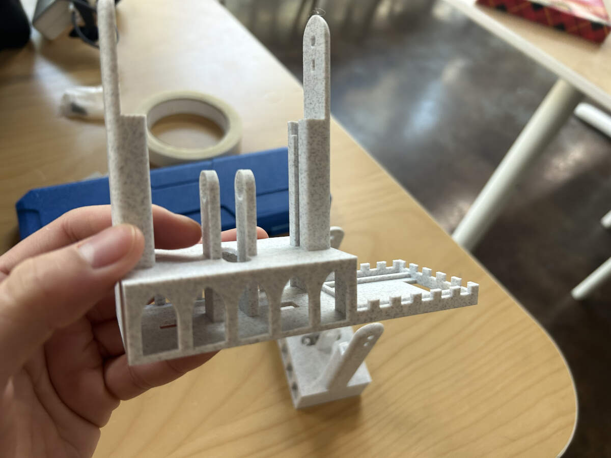
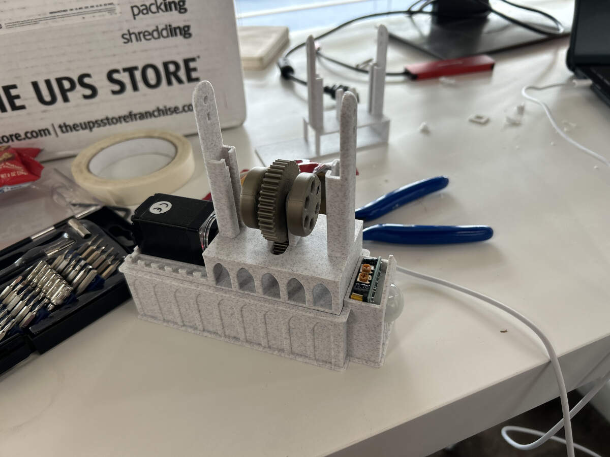
Arches and crenellations were added. Since we were going with dragon imagery and this is typically tied to medieval imagery, we decided to move forward with modifying the base and electronics housing to make them look like a gothic cathedral.
Extruded lines added around the area where the stepper motor will be located. These will hold it in place.

The center of the base features two smaller “pillars” that go through the first floor of the base. These pillars were extended to now reach the second floor of the base so that way they did not require any support.
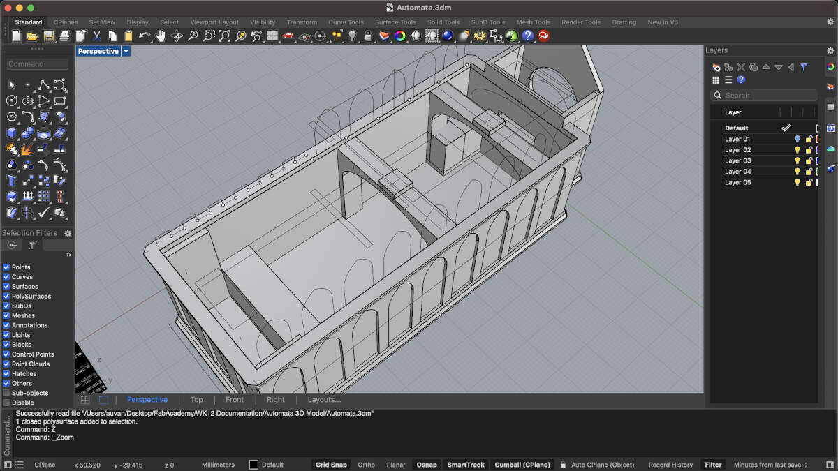
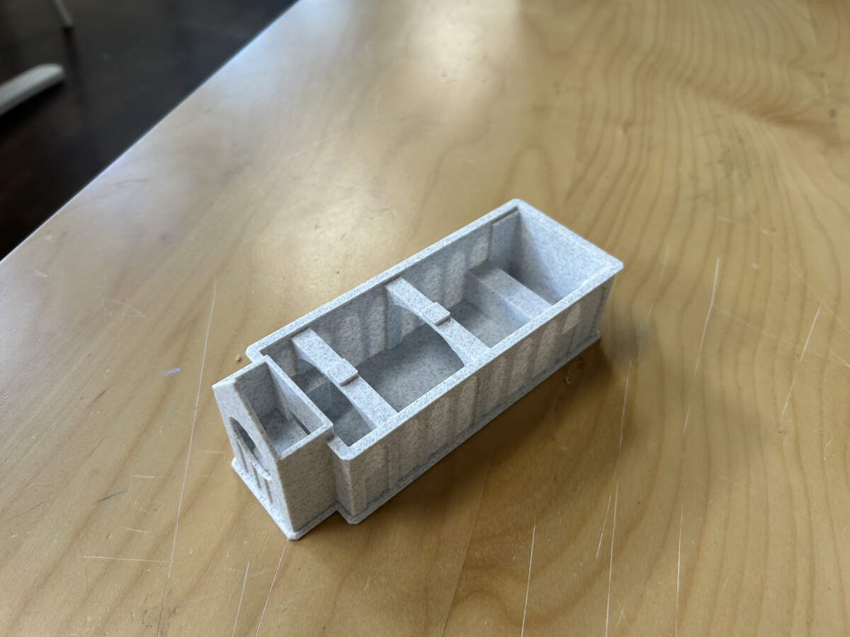
An enclosure was made for the custom electronics board. There is a makeshift rose window that will house the PIR sensor. The arches have an extrusion that will slot into a further modified base. The arches will also allow the board to slide through.
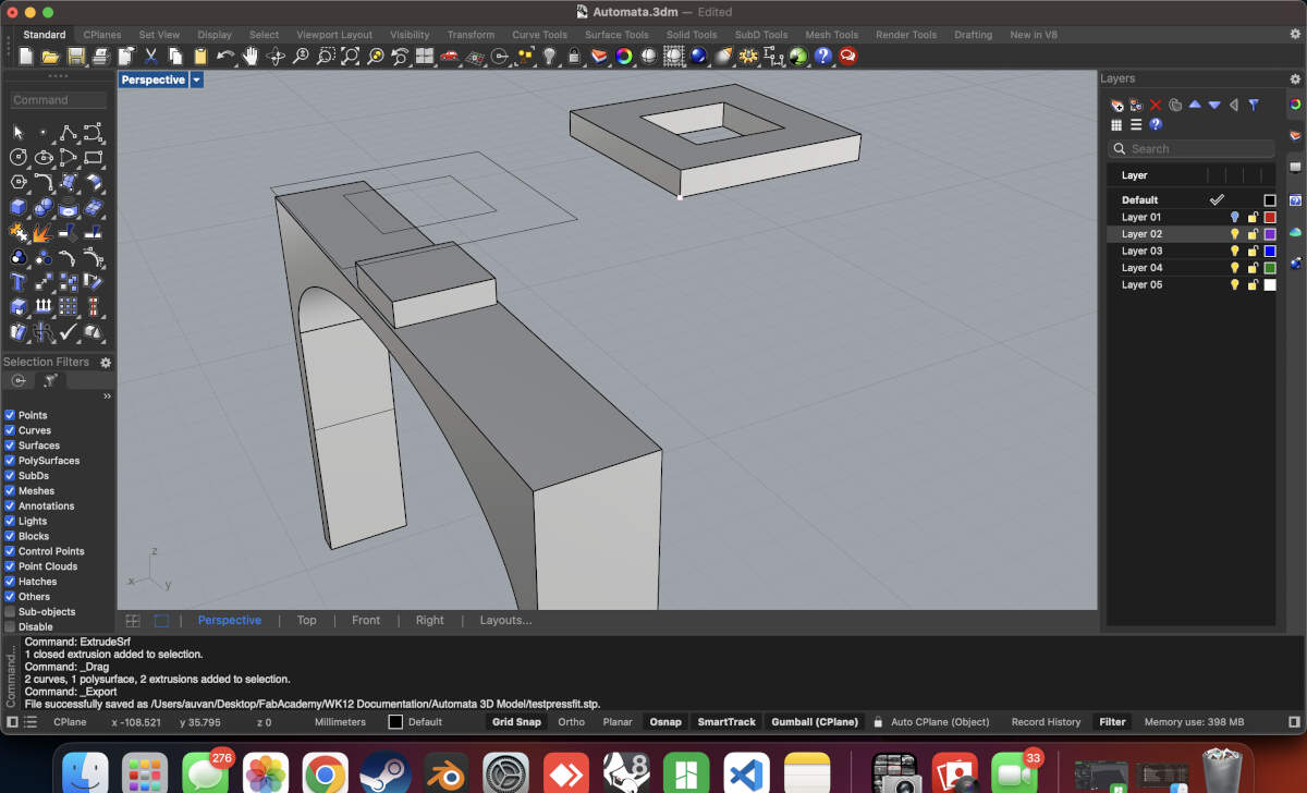
Tolerance tests were created to ensure that the slots worked perfectly before printing the full model. These tolerances were also used to modify the base so that it fit onto the electronics enclosure as well.
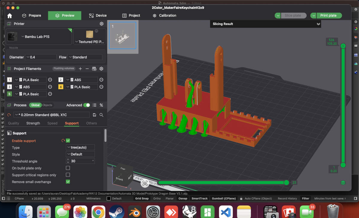
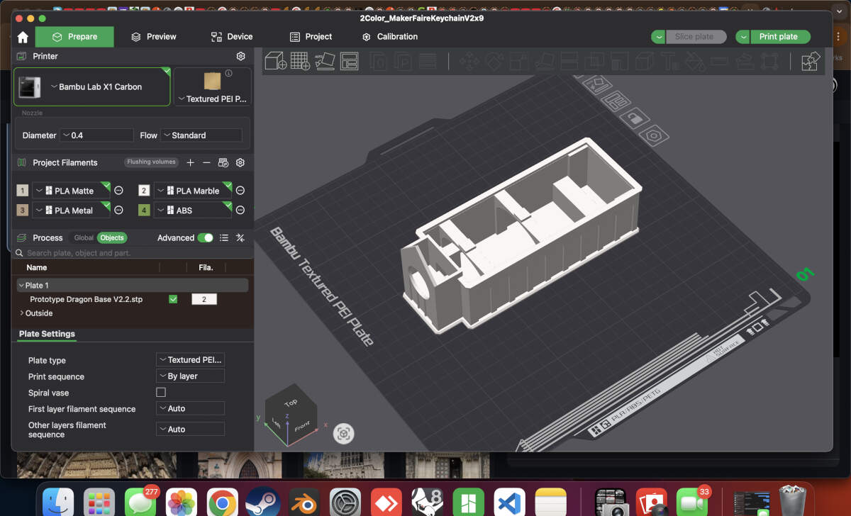
When both models were ready, they were sent to print.
The Build
Base and enclosure print successful. Only required some post processing to remove supports.
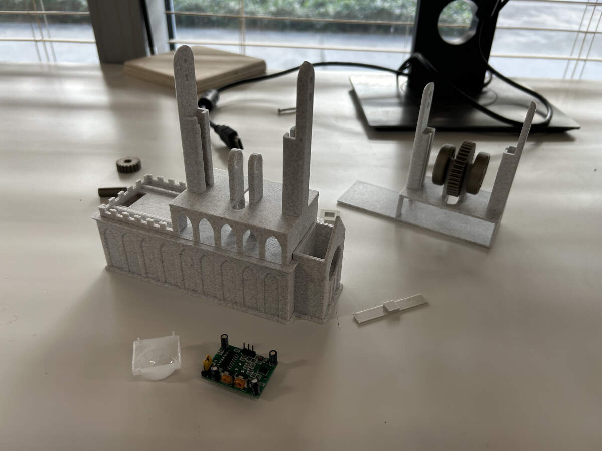
Both prints slot into one another just fine.
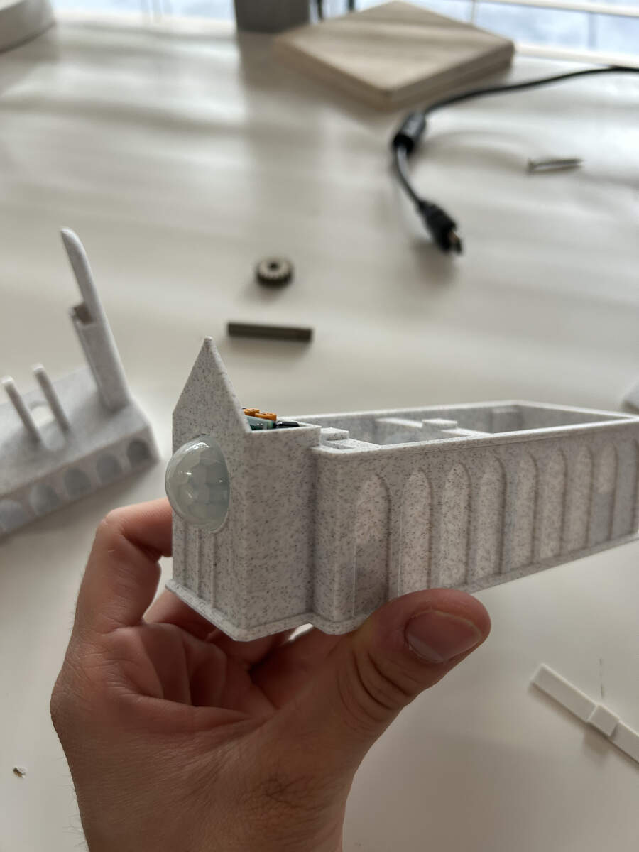
The PIR Sensor fits into place.
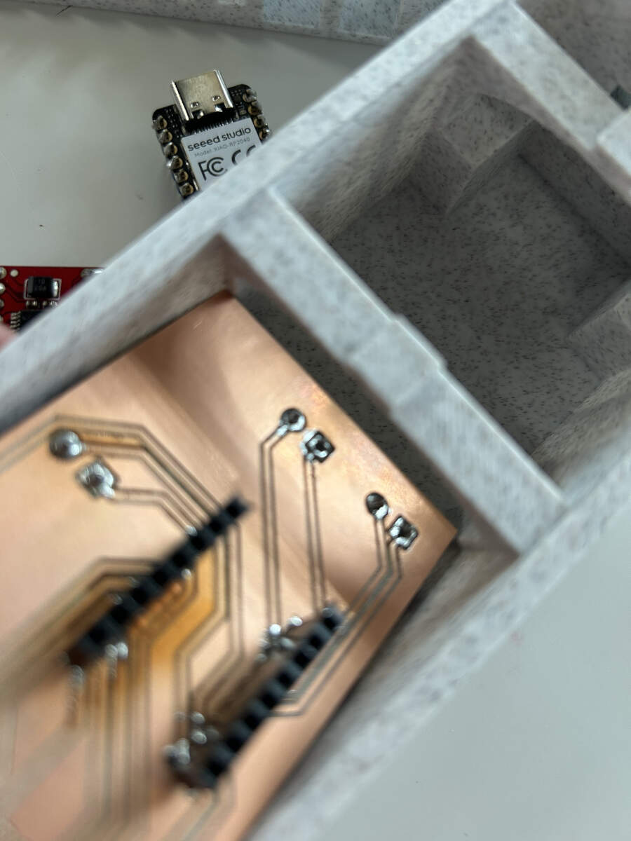
Board put together. There was an attempt to place it inside the enclosure but it was far too large. Even though the board was milled to fit inside the enclosure, Augusto forgot to account for the arches that were put in place so he had to sand them down using a belt sander in the shop.
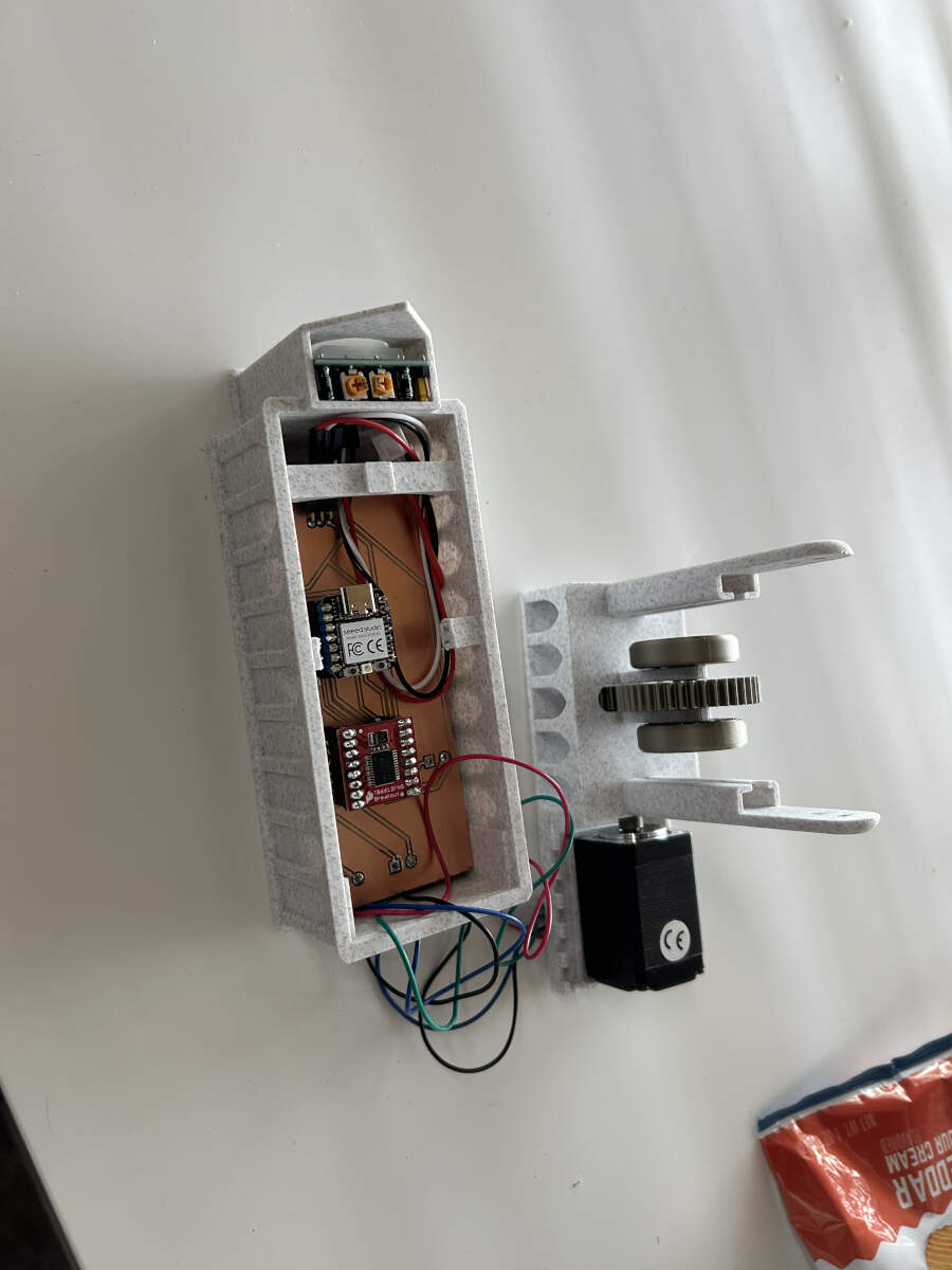
There were a few other hiccups encountered when trying to put the build together. While the board now fit inside the enclosure, there was a realization that the microcontroller would not fit inside because the arch was blocking it from entering its stands. This was a design flaw that was overlooked by Augusto so to quickly resolve the problem and submit the assignment on time, he used a pair of flush cutters to remove that arch allowing for clear entry. Additionally, it was realized that the microcontroller would require power of its own. This was another design flaw overlooked when designing the 3D model so Augusto drilled a hole in the side of the model all for the sake of testing the prototype.
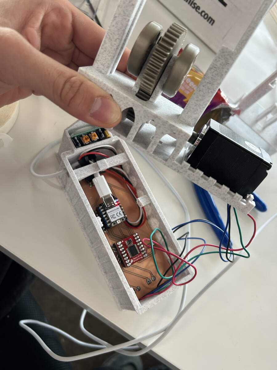
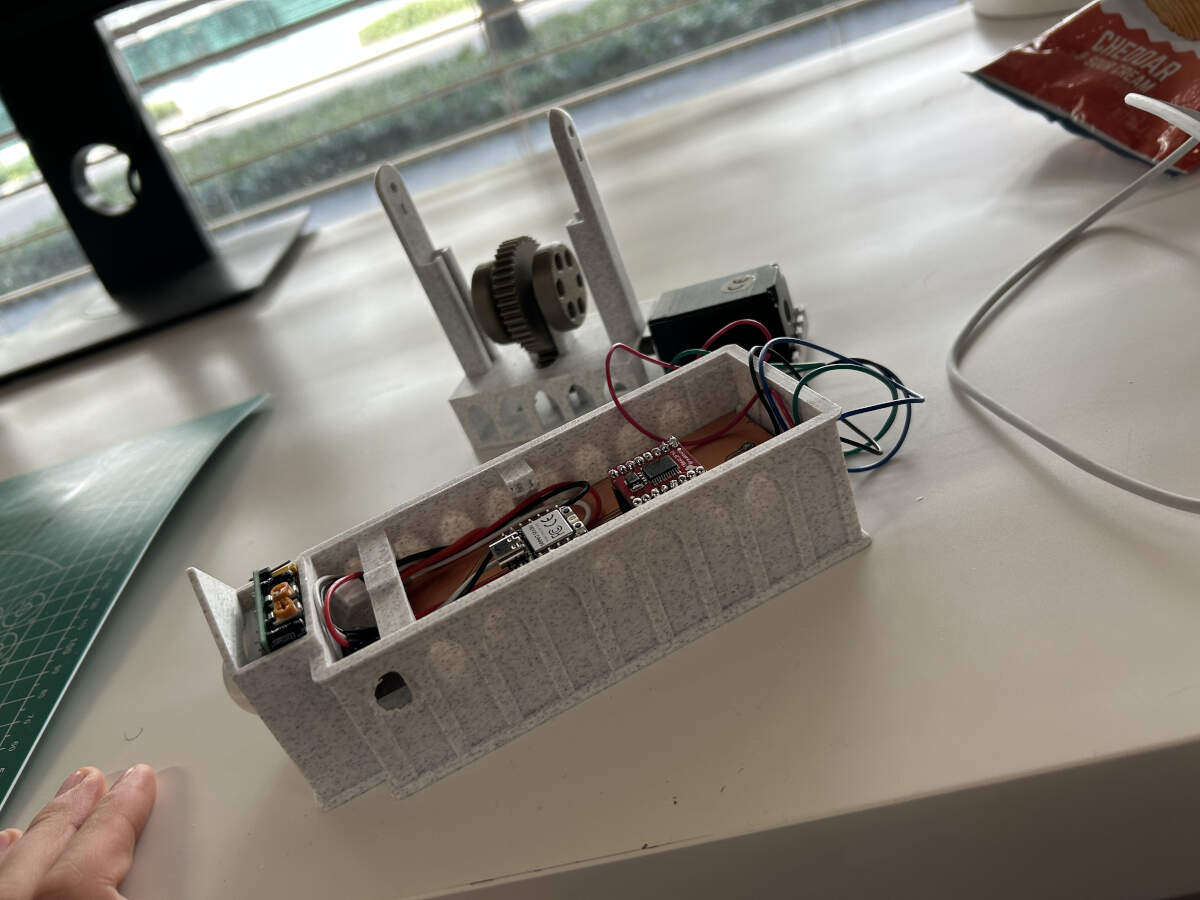
Augusto was able to put all the necessary components and cables in place, especially after the last minute alterations.
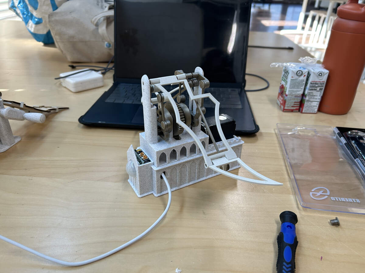
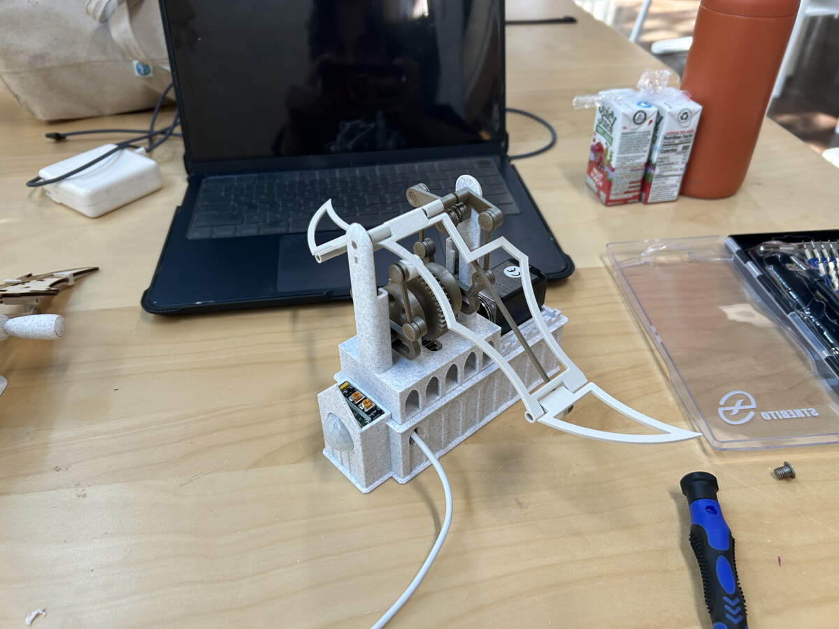
The build was completed albeit with a few hiccups here and there. With it working and in order all that was missing now was to transfer the dragon wings and clips from the earliest print to the newer model in addition to adding the dragon body to the top of the model. All of these later additions can be seen in the video below and in final presentation video at the top of this entry.
Future Improvements to Consider
- Smaller PCB Design
- Larger Enclosure for PCB ensuring easier access or no clipping.
- No clips for wings, fasteners or bolts or alternative instead. Hopefully without appearance of traditional hardware, instead designed to fit aesthetic of machine.
- Not drilling hole in model. Instead design the PCB in manner that places microcontroller on the side of the base for easy external access.