Embedded Systems Assignment
Group Assignment
Demonstrate and compare the toolchains and development workflows for available embedded architectures.
Document your work to the group work page and reflect on your individual page what you learned.
Individual Assignment
Browse through the datasheet for your microcontroller.
Write a program for a microcontroller, and simulate its operation, to interact (with local input and/or output devices) and communicate (with remote wired or wireless connection).
Group Assignment - Comprehensive Analysis of Microcontrollers: Arduino Uno vs ESP32-CAM
Introduction
This project compares Arduino Uno and ESP32-CAM in terms of specifications, functionalities, applications, and performance.
Microcontroller Pinouts
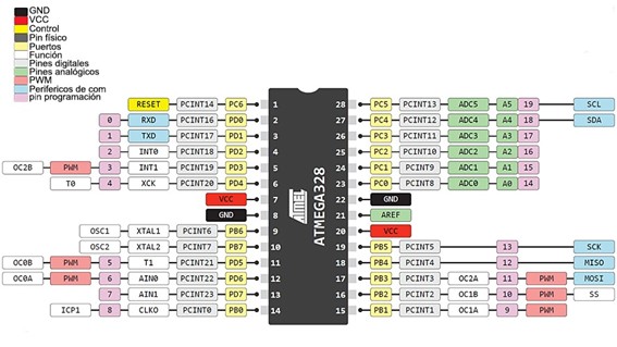
Arduino Uno
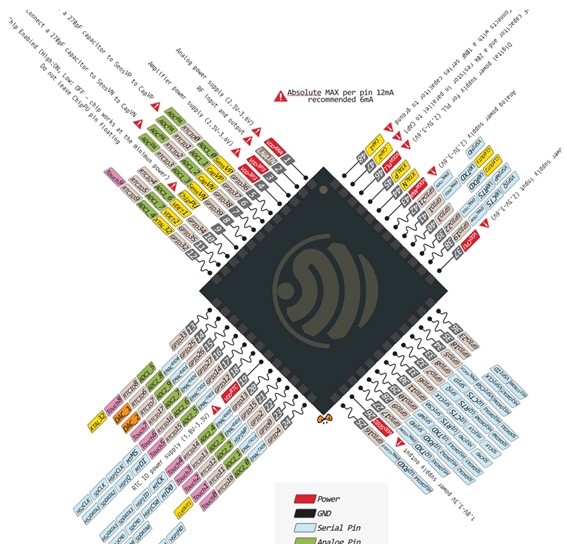
ESP32-CAM
Comparative Table
| Feature | Arduino Uno | ESP32-CAM |
|---|---|---|
| Microcontroller | ATmega328P | Tensilica Xtensa LX6 |
| Clock Speed | 16 MHz | 160-240 MHz |
| WiFi Connectivity | No | Yes |
| Camera Support | No | Yes (2MP) |
| Price | $12.00 | $17.00 |
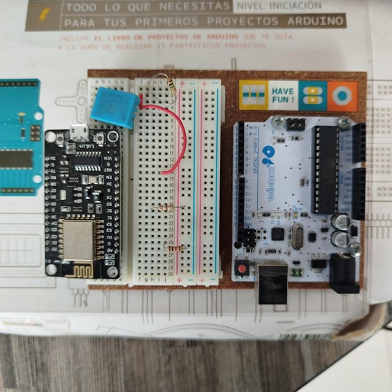
Practical Experiment
Testing Arduino Uno and ESP32-CAM for LED control and image capture via WiFi.
Step-by-Step Guide to Replicate the Group Assignment
Step 1: Gather Required Materials
- Arduino Uno board
- ESP32-CAM module
- Breadboard and jumper wires
- LEDs, resistors, and electronic components
- Power supply (5V for Arduino Uno, 3.3V for ESP32-CAM)
- MicroSD card (for ESP32-CAM image capture test)
Step 2: Understand Microcontroller Pinouts
Review the Arduino Uno and ESP32-CAM pinout diagrams to identify available GPIO pins.
Step 3: Compare Specifications
| Feature | Arduino Uno | ESP32-CAM |
|---|---|---|
| Microcontroller | ATmega328P | Tensilica Xtensa LX6 |
| Clock Speed | 16 MHz | 160-240 MHz |
| WiFi Connectivity | No | Yes |
| Camera Support | No | Yes (2MP) |
Step 4: Build the Test Circuit
Connect the components according to the pinout:
- Arduino Uno: Connect an LED with a 220Ω resistor to a digital pin.
- ESP32-CAM: Connect the OV2640 camera module and a power source (3.3V).
Step 5: Implement & Upload Code
Arduino Uno LED Blinking Code:
void setup() {
    pinMode(13, OUTPUT);
}
void loop() {
    digitalWrite(13, HIGH);
    delay(1000);
    digitalWrite(13, LOW);
    delay(1000);
}
ESP32-CAM Image Capture Code:
Upload the Camera Web Server example in the Arduino IDE and set WiFi credentials.
Step 6: Conduct Practical Experiment
Test LED blinking on Arduino Uno and image capture via WiFi on ESP32-CAM.
Conclusion
For basic projects, Arduino Uno is ideal, while ESP32-CAM is better for IoT and image processing applications.
Comparison of Toolchains and Workflows
Step-by-step guide to setting up and working with different embedded architectures on Windows.
1. AVR (ATtiny and ATmega)
Installing Tools
- Download and install WinAVR
https://sourceforge.net/projects/winavr/C:\WinAVR\bin to the system PATH.Compiling and Programming AVR
Write C code in a file main.c:
#define F_CPU 1000000UL
#include <avr/io.h>
#include <util/delay.h>

int main(void) {
    DDRB |= (1 << PB0);
    while (1) {
        PORTB ^= (1 << PB0);
        _delay_ms(500);
    }
}
Compile with AVR-GCC
avr-gcc -mmcu=atmega328p -Os -o main.elf main.c
avr-objcopy -O ihex main.elf main.hex
Upload the Code with avrdude
avrdude -c usbasp -p m328p -U flash:w:main.hex:i2. ARM Cortex-M (STM32 and SAMD)
Installing Tools
- Download and install GCC ARM Embedded from
https://developer.arm.com/downloads/-/gnu-rm - Install OpenOCD from
http://gnutoolchains.com/arm-eabi/openocd/
Compile with arm-none-eabi-gcc
arm-none-eabi-gcc -mcpu=cortex-m4 -mthumb -o main.elf main.c
arm-none-eabi-objcopy -O binary main.elf main.bin
Upload the Code with OpenOCD
openocd -f board/stm32f4discovery.cfg -c "program main.bin verify reset exit"3. ESP32 (Xtensa and RISC-V)
Installing Tools
- Download and install ESP-IDF from
https://github.com/espressif/esp-idf
Compile with idf.py
idf.py buildFlash the Code
idf.py flash4. Raspberry Pi RP2040
Installing Tools
- Download and install Pico SDK from
https://github.com/raspberrypi/pico-sdk - Install CMake from
https://cmake.org/download/ - Install Ninja from
https://github.com/ninja-build/ninja/releases
Compile with CMake and Ninja
mkdir build && cd build
cmake ..
ninja
Upload the Code
Connect the RP2040 in bootloader mode and copy the .uf2 file to the device.
Conclusion
This guide provides a structured approach to setting up and working with various embedded architectures, covering AVR, ARM Cortex-M, ESP32, and Raspberry Pi RP2040. Each toolchain has its specific workflow, but all share common steps: installing the required tools, writing and compiling code, and flashing the compiled binary onto the target hardware. Understanding these processes helps developers choose the right platform for their embedded system projects.
Individual Assignment - Servo Motor Control with ESP32
Introduction
This project demonstrates how to control a servo motor using an ESP32 microcontroller. We utilize the ESP32Servo.h library to interface with the servo.
Objective
The goal is to program an ESP32 to control a servo motor, moving it from 0° to 180° in increments of 10° and resetting to 0°.
Materials Required
- ESP32 development board
- Servo motor (SG90 or similar)
- Breadboard and jumper wires
- Power supply (5V from ESP32 or external source)
- Wokwi simulation
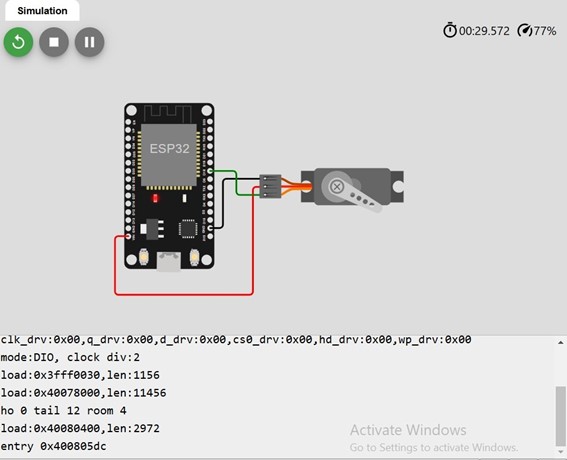
Circuit Diagram
The following wiring scheme is used:
- Servo signal (orange) → ESP32 GPIO18
- Servo VCC (red) → 5V
- Servo GND (black) → GND
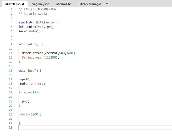
Code Implementation
#include <ESP32Servo.h>

int control = 18, p = 0;
Servo motor;

void setup() {
    motor.attach(control, 500, 2400);
    Serial.begin(115200);
}

void loop() {
    p = p + 10;
    motor.write(p);

    if (p == 180) {
        p = 0;
    }

    delay(1000);
}
Simulation & Testing
The circuit was tested on Wokwi. The servo motor successfully moves in 10° increments until reaching 180°, then resets.
Observations
- Current implementation does not return smoothly to 0°.
- External power may be needed to avoid jitter.
Conclusion
This project showcases basic servo control with ESP32, which can be further expanded for robotics and automation.