Group Assignment - Mechanical Design (part 1 of 2)
Design a machine that includes mechanism + actuation + automation + application
Build the mechanical parts and operate it manually
Document the group project
Individual Assignment
Document your individual contribution
Group Assignment - Mechanical Design (part 2 of 2)
Actuate and automate your machine
Document the group project
Individual Assignment
Document your individual contribution
Manuel Ayala-Chauvin Institution: Fablab - Universidad Tecnológica Indoamérica Year: 2025
Low-Cost CNC Milling Machine with Continuity Sensor
Team: Manuel Ayala-Chauvin, Sandra Nuñez-Torres Institution: Fablab - Universidad Tecnológica Indoamérica Year: 2025
Project Overview
This project aimed to design, build, and automate a low-cost CNC milling machine equipped with a
continuity sensor to map surface profiles on copper plates.
By applying a concurrent engineering approach, the team simultaneously developed the mechanical,
electronic, and software systems to achieve a modular, affordable, and replicable machine for
educational and research environments.
Mechanical Design (Part 1) — Group Assignment
Machine Concept
The machine was conceived as a three-axis Cartesian CNC with a leadscrew drive system, capable of
manual and automated operation.
The design prioritized low-cost materials, ease of fabrication, modularity for future upgrades, and
sufficient precision for contour line generation.
Mechanical Design and Manual Testing
The frame was built using aluminum profiles and AISI 1020 steel reinforcements. Movement was guided
by linear rails (12 mm) and driven by 8 mm leadscrews with a 2 mm pitch.
Before installing electronics, the machine was manually operated via hand cranks to validate
mechanical alignment, smoothness of motion, and structural rigidity.
FEA simulations predicted a maximum displacement of 0.0236 mm under load, which manual testing later
confirmed as acceptable.
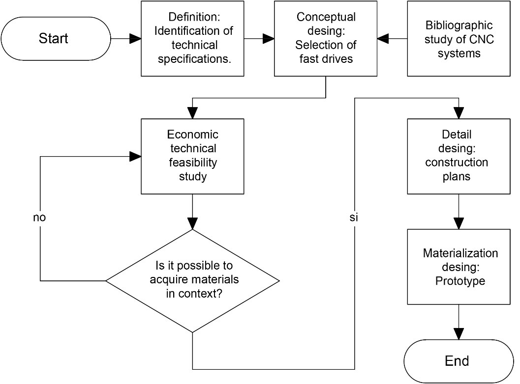
Methodology
The mechanical design was based on a four-stage method:
Requirements: Define specifications based on cost, flexibility, modularity, and
precision.
Conceptual Design: Modeled in SolidWorks; determined structure, actuation, and
materials.
Detailed Design: Generated CAD files, FEA simulations to validate structure.
Prototype Fabrication: Built physical structure with aluminum profiles and AISI
1020 steel reinforcements.
The diagram presents the systematic design process used for the low-cost CNC milling machine
project. It begins with the identification of technical specifications, which define the project's
fundamental requirements such as work area dimensions, desired precision, and operational capacity.
The next step involves conceptual design, focusing on selecting suitable motion systems like
leadscrews and motors. A bibliographic study of existing CNC technologies is conducted in parallel
to enrich the conceptual framework. Once the preliminary design is ready, a technical and economic
feasibility study is carried out to evaluate material availability and budget constraints. If
materials are not obtainable within the project’s context, the process loops back to redefine
specifications and adjust the design accordingly. When feasibility is confirmed, the project
advances to the detailed design phase, generating complete CAD models, technical drawings, and part
lists. The final stage is the materialization phase, where the prototype is constructed based on the
finalized plans. This iterative and feedback-driven process ensures the CNC machine is not only
functional and efficient but also economically viable and adaptable to local fabrication
capabilities.
Group Collaboration
Manuel focused on mechanical design, material selection, and manual assembly.
Sandra designed the usability aspects, including form factor, accessibility, and ergonomic
considerations.
Developed full SolidWorks CAD models for frame, motion, and assembly systems.
Performed mechanical dynamic calculations to select actuators.
Manually fabricated and assembled mechanical systems, aligning and calibrating axes.
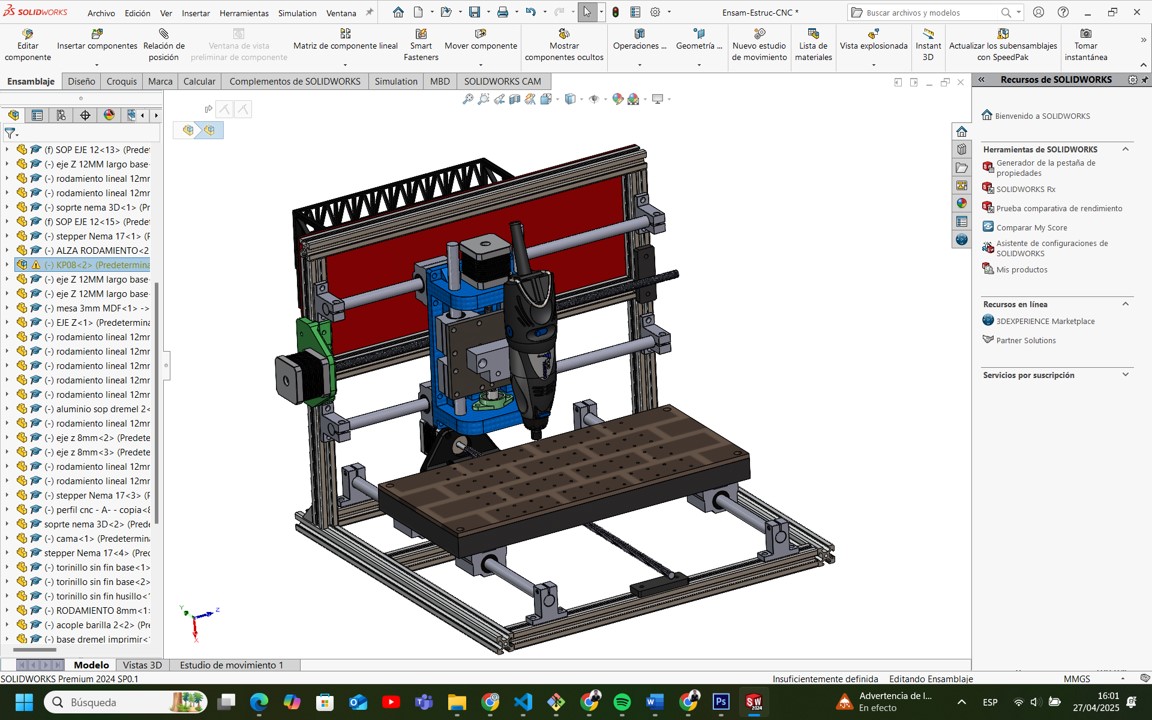
1. Development of Full SolidWorks CAD Models for Frame, Motion, and Assembly Systems
As the mechanical design leader, Manuel was responsible for creating detailed three-dimensional CAD
models of the entire CNC milling machine using SolidWorks. This work included modeling the primary
structure (frames and supports), the motion transmission system (leadscrews, couplings, linear
guides), and the mechanical subassemblies (motor mounts, sensor holders, spindle supports). Each
component was designed parametrically to allow for easy adjustments and scalability. The modeling
process ensured that interferences were minimized, tolerances were respected, and that future
modifications, such as enlarging the working area or integrating new actuators, could be
accomplished efficiently. Additionally, the CAD models served as the basis for generating technical
drawings for fabrication and assembly documentation.
This screenshot shows the complete CAD model of the machine developed in
SolidWorks.
The left sidebar lists each component and subassembly, such as motors, rods, and bearings.
It demonstrates that the project followed good parametric modeling practices, ensuring easy
modifications or scaling of the machine.
The final 3D design confirms that all motion systems are correctly aligned and mechanically
feasible.
2. Performance of Mechanical Dynamic Calculations to Select Actuators
Manuel conducted comprehensive mechanical analyses to determine the necessary force and torque
requirements for each axis movement. Using basic dynamic and static formulas, he calculated the load
requirements based on the weight of moving elements, friction coefficients, and desired acceleration
values. Based on these calculations:
The maximum required force to move the system was estimated at 12.45 N.
The corresponding required torque was calculated at 0.00396 Nm.
Given these results, he selected NEMA 17 stepper motors (rated at 0.3 Nm torque) to provide a
safety margin greater than 6 times the calculated needs. This approach ensured that the motors could
handle not only the operational forces but also unexpected resistance during prolonged usage, enhancing
the machine’s reliability and operational lifetime.
3. Manual Fabrication and Assembly of Mechanical Systems, Alignment and Calibration of Axes
After the fabrication of individual parts, Manuel personally led the mechanical assembly of the CNC
machine. This process required careful squaring and alignment of the frame, precision positioning of
the linear rails, and exact installation of leadscrews and bearings. Mechanical calibration was
critical: each axis was manually moved and adjusted to eliminate excessive friction, misalignment,
or backlash. Dial indicators, calipers, and alignment jigs were used to validate and correct the
mechanical setup, ensuring smooth and accurate movement across all three axes (X, Y, and Z). These
manual efforts directly contributed to the machine’s final precision during both manual and
automated operations.
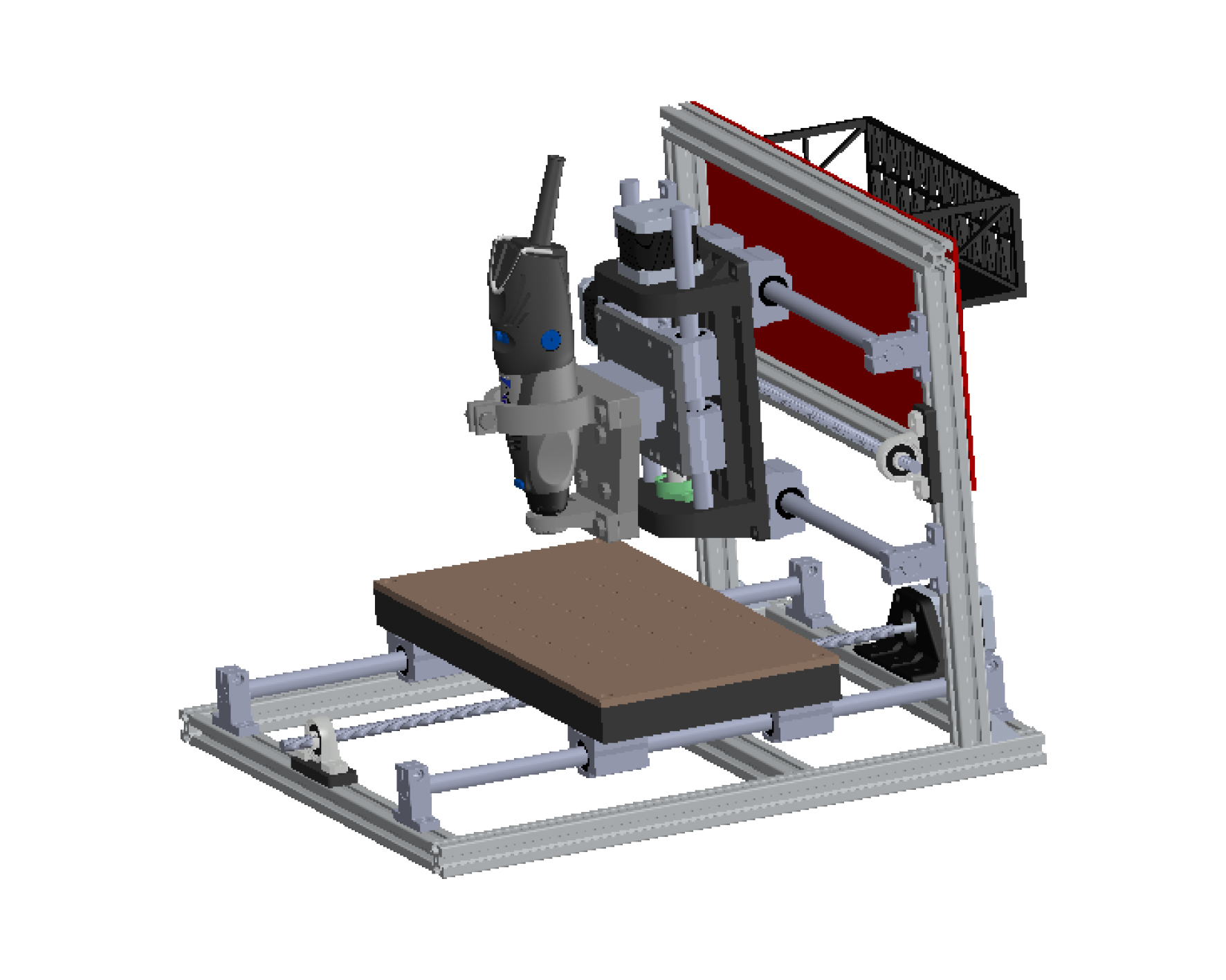
This image displays the fully assembled CNC milling machine ready for operation.
It highlights the Dremel spindle mounted correctly, the bed aligned with X and Y axis movement, and
the general structural stability of the design.
The aluminum and steel frame ensures a balance between weight and rigidity, vital for precision
scanning and machining tasks.
Sandra Nuñez Torres
Designed the outer shell, operator interfaces, and panel arrangements.
Validated user access to key components during manual operation.
Documented usability testing during early mechanical validation phases.
1. Design of the Outer Shell, Operator Interfaces, and Panel Arrangements
One of the fundamental contributions was the design of the external structural elements that house
and protect the CNC milling machine’s functional components. This included the development of an
ergonomic and protective outer shell that minimizes external particle ingress, improves user safety,
and optimizes aesthetics. Operator interfaces, such as emergency stop locations, manual access
points for tool changes, and the positioning of control buttons, were carefully analyzed and
incorporated. Additionally, the red rear protection panel was strategically designed not only to
shield sensitive components but also to serve as a mounting platform for cable management and future
electronics (controllers, sensors). The entire layout was modeled in SolidWorks to ensure seamless
integration with the mechanical motion system without causing interferences.
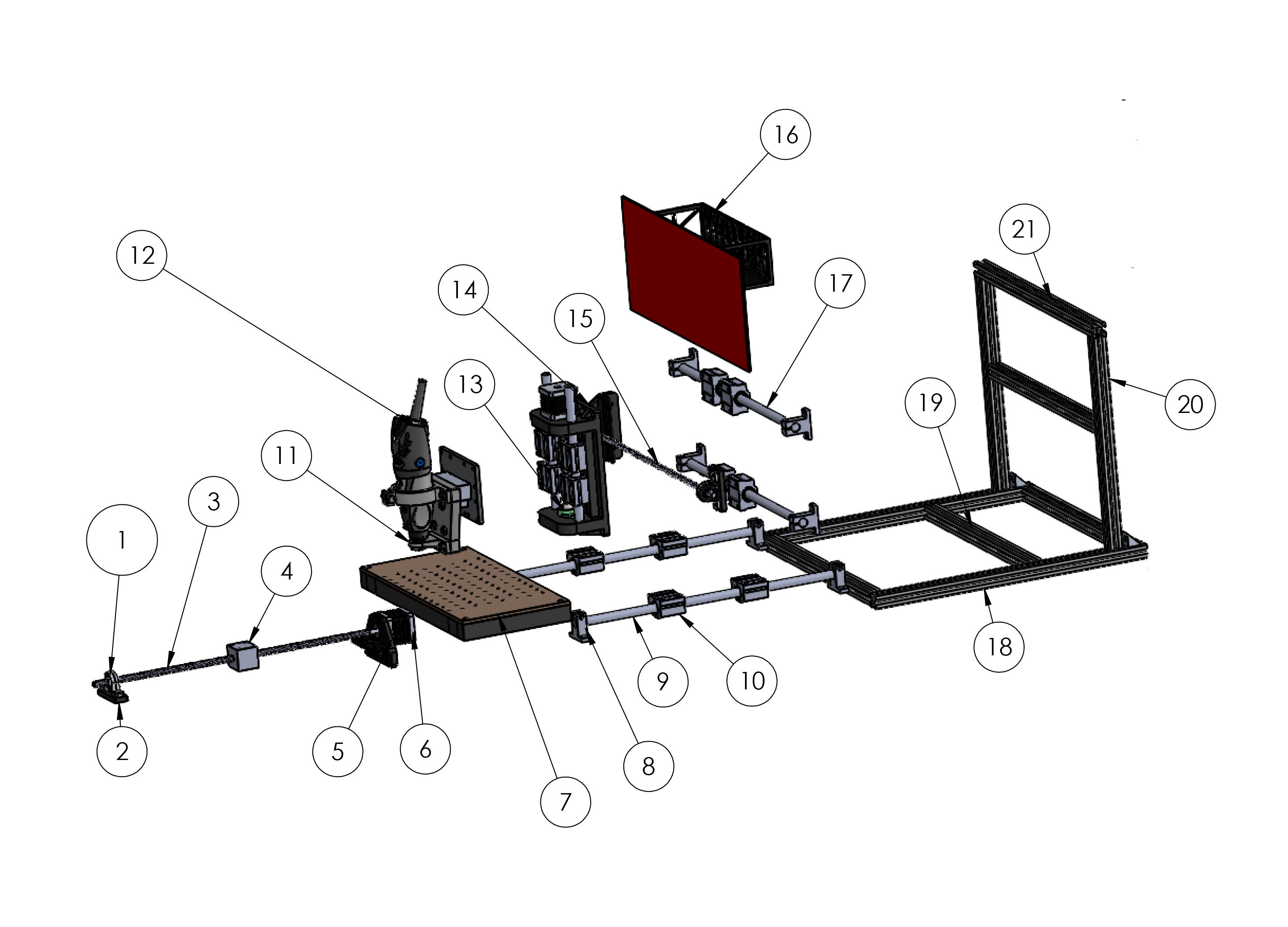
This image shows an exploded view of the CNC milling machine, where each component
is separated to visualize its positioning and assembly order.
Key elements include the linear rails (8 and 9), leadscrews (1 and 5), spindle mount (11), rear
frame (20 and 21), and the protective electronics panel (16).
This view is essential to understand how parts fit together and how to proceed during assembly or
maintenance.
2. Validation of User Access to Key Components During Manual Operation
Prior to the automation phase, manual validation of the CNC machine was critical. Sandra conducted a
series of usability inspections to confirm that operators could comfortably access critical areas
such as: - The spindle head (for tool attachment and maintenance), - The bed surface (for part
loading and securing), - Leadscrew supports and guide rails (for maintenance and alignment
verification). Adjustments were proposed and implemented, such as slight repositioning of the bed
relative to the frame and additional clearances in the Z-axis structure, to enhance ease of use
without compromising mechanical performance. These actions directly contributed to reducing setup
and maintenance times, improving the overall machine usability.
3. Documentation of Usability Testing During Early Mechanical Validation
A systematic usability testing protocol was developed, involving practical walkthroughs of typical
machine operations in a manual mode. Sandra documented ergonomic bottlenecks, safety hazards, and
operator fatigue risks. Recommendations arising from this testing included: - The placement of cable
routing away from operator access paths, - The suggestion of installing a transparent protective
screen for moving parts, - Guidelines for labeling manual control interfaces clearly. These
improvements were integrated into the second mechanical validation cycle and contributed
substantially to enhancing the machine’s operational experience, particularly for new or non-expert
users. All findings were archived in the project’s design documentation to inform future iterations
or scalability projects.
Machine Design (Part 2) — Group Assignment
Actuation and Automation
The machine was automated by integrating three NEMA 17 stepper motors driven by DRV8825 drivers,
controlled through an Arduino UNO with a CNC Shield.
A fine-contact continuity sensor was connected to detect surface variations along the Z-axis.
Toolpaths were generated using Vectric Aspire and executed with Universal G-Code Sender.
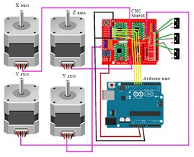
The image illustrates the electronic control system architecture implemented for the low-cost CNC
milling machine. At the center of the system is an Arduino UNO, which serves as the main
microcontroller, responsible for interpreting G-code commands and translating them into precise
motion instructions. Mounted on top of the Arduino is a CNC Shield, which organizes and routes the
electrical connections to the stepper motor drivers and limit switches. Four NEMA 17 stepper motors
are connected: one motor controls the X-axis movement, one controls the Z-axis vertical movement,
and two motors are connected to the Y-axis to ensure synchronized and stable motion of the machine
bed. Each motor is powered and driven independently through the CNC Shield, allowing fine control
over direction and steps. This modular setup ensures that the CNC machine can achieve high precision
while maintaining a low-cost, open-source hardware base. The use of a CNC Shield simplifies wiring
complexity and enhances system maintainability, making the machine more accessible to students,
researchers, and DIY makers. Furthermore, the dual-motor configuration on the Y-axis significantly
improves structural stability and alignment during fast movements, which is critical for maintaining
milling accuracy. Overall, this configuration represents an efficient, scalable, and easily
replicable solution for educational and small-scale manufacturing environments.
Testing after Automation
The automated system was tested over copper plates to verify contour mapping accuracy.
Calibration of stepper motor steps/mm and sensor response ensured consistent scanning performance.
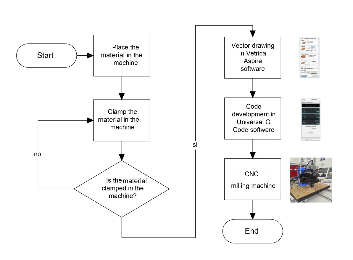
The figure shows the workflow used to machine any type of material on the low-cost CNC milling
machine. The process begins by placing the material inside the machine and securely clamping it
using holding systems. If the material is not properly fixed, adjustments must be made to ensure a
firm hold, essential to prevent displacement during machining. Once secure clamping is verified, the
toolpath is designed using Vectric Aspire software, where the cutting paths are defined.
Subsequently, the vector design is converted into G-code using Universal G-Code Sender software,
setting the movement parameters for the axes. Finally, the CNC machine automatically performs the
machining operation on the secured material. This workflow ensures that all steps, from material
preparation to final machining, are performed in a controlled and precise manner, guaranteeing
high-quality results.
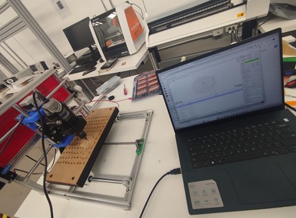
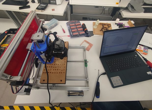
The image shows the CNC milling machine connected to a laptop controlling the machining process via
CAM software. The CNC setup is ready to execute the loaded machining program.
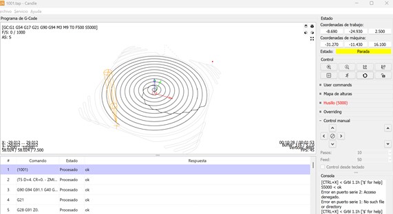
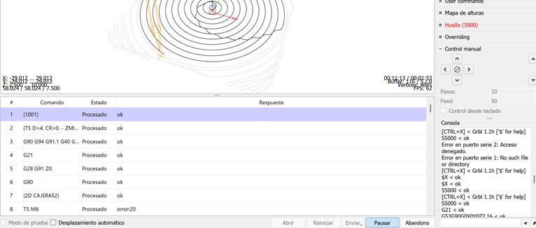
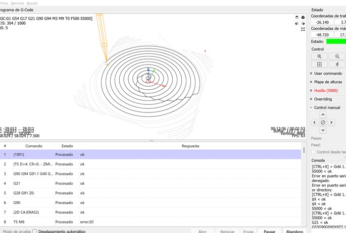
This screenshot displays the programmed toolpaths in a spiral pattern. G-code commands are
successfully processed, with X, Y, and Z axes settings visible, ensuring that the machine is ready
for precise operation.
A detailed view of the G-code console shows each processed command. While most commands are
confirmed as "ok", some errors such as error20 (tool change) are noted, demonstrating real-time
system feedback.
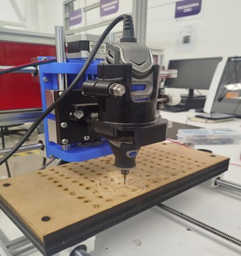
A close-up image of the milling machine engraving a circular path onto an MDF sheet. The tool is
visibly executing the programmed path, confirming correct translation from digital to physical.
This image shows the active execution of the machining process with live tracking of tool movements
and processed commands, confirming real-time system monitoring.
A top view of the complete CNC workstation, including the machine, laptop, tools, and materials.
This setup highlights the comprehensive preparation for digital fabrication operations.
Group Collaboration
Manuel integrated electronics, programmed the Arduino, and developed G-code sequences.
Sandra focused on usability and safety during automated operations, including layout
optimizations for cables and user interface design.
Machine Design (Part 2) — Individual Assignment
Manuel Ayala-Chauvin
Firmware Development: Programmed the Arduino firmware responsible for CNC
motion control, integrating routines for the precise management of stepper motors and sensor
feedback.
Component Calibration: Calibrated stepper motors to ensure accurate
displacements and adjusted the continuity sensor to guarantee precise surface detection during
scanning processes.
Testing and Optimization: Conducted complete testing cycles using G-code files,
validating the correct interpretation of programmed paths. Subsequently optimized
feedrate and acceleration parameters, achieving smoother performance and
reducing mechanical wear on the machine.
Sandra Nuñez Torres
Usability Documentation: Conducted detailed documentation of usability
observations after automation implementation. Suggested ergonomic improvements aimed at
facilitating operator interaction with the CNC, focusing on comfort and reducing fatigue risks.
Participation in Automated Testing: Participated in automated system testing
sessions, verifying both operator safety and workflow efficiency, ensuring that operational
protocols met basic ergonomics and industrial safety standards.
Results and Analysis
Experimental Testing
100 surface scans were performed on copper plates (100x100 mm).
This project successfully demonstrated the viability of designing and constructing a low-cost
CNC
milling machine for contour mapping applications.
Through meticulous mechanical design, careful component selection, and synchronized software
development, a highly functional and accessible machine was built.
The collaboration between mechanical design and usability specialists ensured that both
technical
performance and user experience were addressed from the earliest stages.
Future improvements will explore higher resolution sensing, faster scanning speeds, and extended
machining capabilities.
Week 12: Conclusion
During Week 12, we successfully applied the complete cycle of mechanical and machine design
principles to create a functional, low-cost CNC milling machine capable of surface scanning and
material machining. The collaborative effort between mechanical structure development,
electronics integration, and usability validation allowed us to build a robust and replicable
system. By following concurrent engineering practices, we shortened development time, reduced
iteration errors, and achieved a high level of integration across mechanical and electronic
subsystems. The experience emphasized the critical importance of interdisciplinary
collaboration, early validation through manual operation, and structured design methodologies.
This project not only strengthened our technical skills in CAD modeling, dynamics calculations,
electronics programming, and CNC automation but also reinforced key soft skills such as
teamwork, documentation, and project planning. Moving forward, we aim to refine the system with
higher precision sensors, improved control interfaces, and expanded machining capabilities for
broader applications.
Resource Download
Click the button below to access and download all available materials.