Document your work to the group work page and reflect on your individual page what
you learned
Individual Assignment
design, build and connect wired or wireless node(s) with network or bus addresses
and a local input and/or output devices
Manuel Ayala-Chauvin Institution: Fablab - Universidad Tecnológica Indoamérica Year: 2025
Group Assignment Networking and Communication
Team: Manuel Ayala-Chauvin, Sandra Nuñez-Torres Institution: Fablab - Universidad Tecnológica Indoamérica Year: 2025
1. Objective
The goal of this project was to design, build, and connect wired or wireless nodes with network or
bus addresses, integrating local input and/or output devices to simulate a basic Internet of Things
(IoT) interaction between two embedded systems.
2. Introduction
For this assignment, we implemented a communication system using two ESP32-CAM
modules. Each device was independently powered and equipped with WiFi capabilities, allowing them to
interact through a local wireless network. A crucial feature of the ESP32-CAM is the onboard LED
connected to GPIO4, which was leveraged to visually confirm the successful transmission and
reception of commands between devices.
3. Materials Used
2 ESP32-CAM development boards
Independent 5V power supplies for each board
WiFi network (created using a router or mobile hotspot)
Arduino IDE installed with WiFi.h and HTTPClient.h libraries
USB-to-Serial adapters for flashing the ESP32-CAM boards
Push button (for the client device)
Resistors (for button pull-down configuration)
Jumper wires and prototyping breadboard
4. Development Process
4.1. Hardware Overview and Initial Setup
Each ESP32-CAM module was mounted on a breadboard and connected to its respective power source. Basic
pin configurations were completed, including preparing a push button circuit for the client device
to trigger HTTP requests.
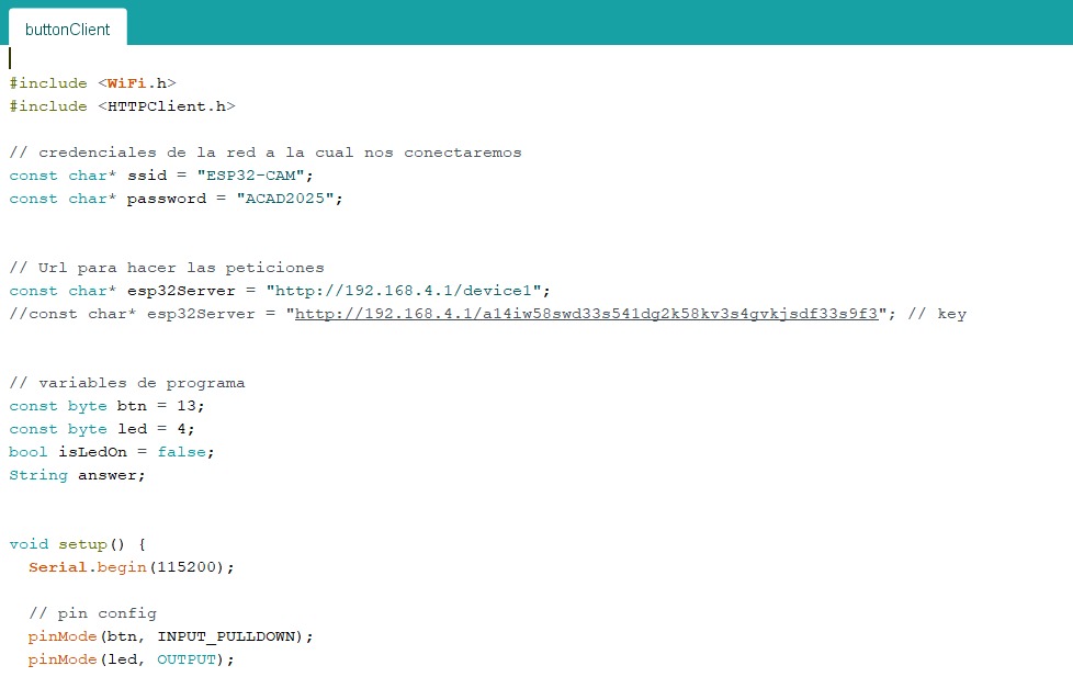
					#include
#include

// credenciales de la red a la cual nos conectaremos
const char* ssid = "ESP32-CAM";
const char* password = "ACAD2025";

// Url para hacer las peticiones
const char* esp32Server = "http://192.168.4.1/device1";
//const char* esp32Server = "http://192.168.4.1/a14iw58swd33s541dq2k58kx3s4qvkj..."; // key

// variables de programa
const byte btn = 13;
const byte led = 4;
bool isLedOn = false;
String answer;

void setup() {
  Serial.begin(115200);

  // pin config
  pinMode(btn, INPUT_PULLDOWN);
  pinMode(led, OUTPUT);
4.2. Network Creation
We configured a local WiFi network using a mobile hotspot or router. One ESP32-CAM was programmed to
operate as a server, constantly listening for HTTP requests, while the other functioned as a client
capable of sending HTTP requests to the server's IP address whenever the button was pressed.
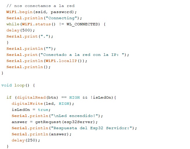
4.3. Establishing WiFi Connection
Both ESP32-CAM boards were programmed with the WiFi credentials of the newly created network. The
server board printed its local IP address upon successful connection, which was noted and programmed
into the client board for precise targeting of HTTP requests.
 // nos conectamos a la red
  WiFi.begin(ssid, password);
  Serial.println("Connecting");
  while (WiFi.status() != WL_CONNECTED) {
    delay(500);
    Serial.print(".");
  }
  Serial.println("");
  Serial.print("Conectado a la red con la IP: ");
  Serial.println(WiFi.localIP());
  Serial.println();
}

void loop() {
  if (digitalRead(btn) == HIGH && !isLedOn) {
    digitalWrite(led, HIGH);
    isLedOn = true;
    Serial.println("\nLed encendido!");
    answer = getRequest(esp32Server);
    Serial.println("Respuesta del Esp32 Servidor:");
    Serial.println(answer);
    delay(250);
  }
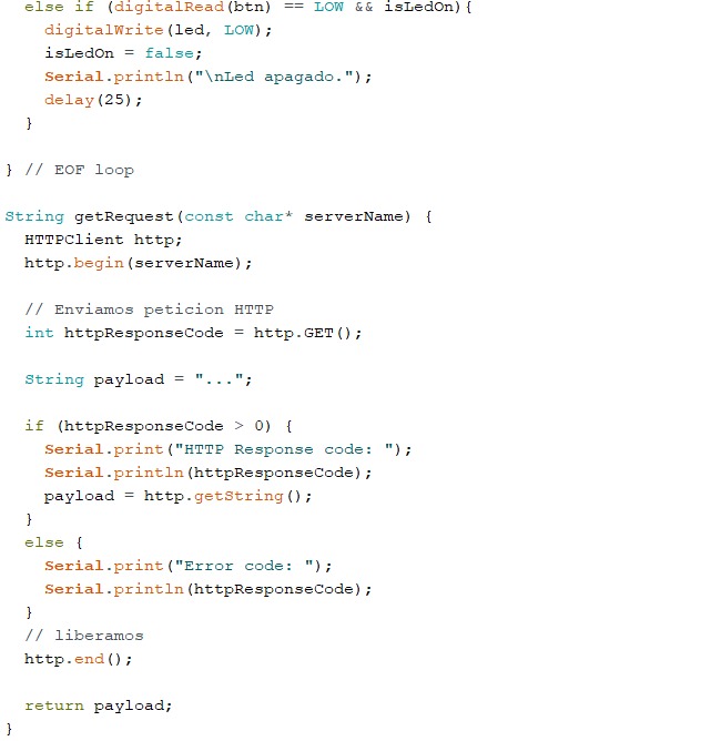
4.4. Device Communication and Interaction
After successful network connection, the client ESP32-CAM continuously monitored the state of the
push button. When the button was pressed, it sent an HTTP GET request to the server ESP32-CAM. Upon
receiving a request, the server toggled its onboard LED state (turning it ON or OFF) depending on
the instruction received, providing immediate visual feedback of communication success.
Care was taken to implement debounce delays in the button reading to ensure accurate and reliable
operation. Additionally, the HTTP response code and payload were printed on the serial monitor for
debugging and verification purposes.
Server-side: Listened for incoming HTTP GET requests and toggled the LED
accordingly. The server also responded with an acknowledgment message back to the client.
Client-side: Continuously monitored the push button. Upon detecting a press, it sent
a GET request to the server and processed the server's response, printing it to the serial monitor
for confirmation.
6. Challenges and Solutions
WiFi Connection Stability: Ensured the network signal strength was adequate and
added reconnection logic if disconnected.
Button Debouncing: Implemented software delay techniques to avoid false
triggering.
HTTP Request Handling: Verified correct URL formats and HTTP status code checks
for robust communication.
7. Conclusion
This group project offered an invaluable opportunity to delve into basic IoT communication between
two embedded devices using WiFi. By building both the server and client logic, we gained a practical
understanding of wireless networking protocols, HTTP communication, and microcontroller programming.
The real-time LED response upon request provided immediate feedback that not only confirmed the
success of our setup but also reinforced the importance of careful configuration and debugging in
networked systems. This foundational exercise prepares us for more complex interconnected systems in
future smart device applications.
Individual Assignment Networking and Communication
1.Objective
The objective of this assignment was to design, build, and connect wired or wireless nodes with
network or bus addresses, integrating local input and/or output devices.
2. Introduction
For this challenge, I decided to create a system that moves a servo motor from a mobile phone using a
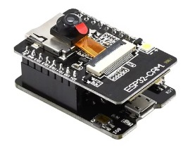
WiFi connection. To accomplish this, I used the versatile ESP32-CAM development
board, known for its built-in WiFi and Bluetooth capabilities, along with an integrated camera.
3. Materials Used
ESP32-CAM development board
SG90 servo motor
Connection wires
Power supply (if needed)
Arduino IDE with WiFi.h and ESP32Servo.h libraries installed
4. Step-by-Step Development
4.1. ESP32-CAM Overview
The ESP32-CAM board provides the connectivity backbone. With its compact design, it is ideal for IoT
projects requiring wireless control.
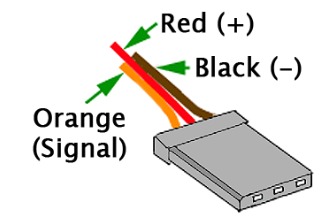
4.2. Wiring the Servo Motor
The servo motor has three wires:
Red: Positive (+5V)
Black/Brown: Ground (GND)
Orange: Signal (PWM)
I connected the orange wire to GPIO4 on the ESP32-CAM, red to 5V, and black to GND.
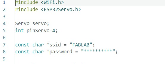
4.3. Setting Up the Code
First, I included the necessary libraries and configured the WiFi credentials:
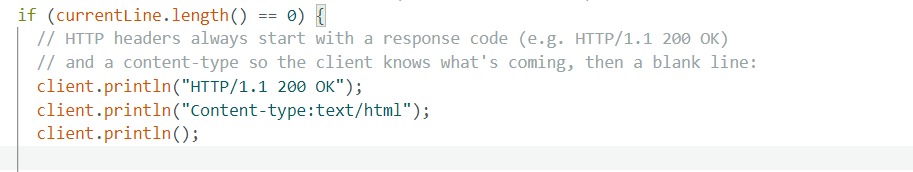
4.4. Building the Web Server
Using simple HTTP responses, I created a lightweight web server to interact with the servo:
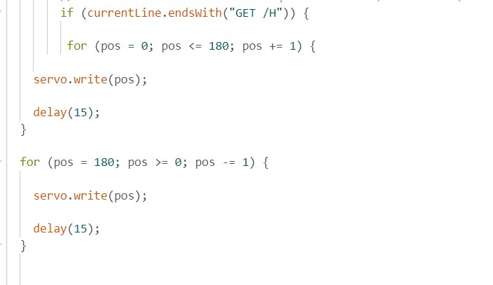
4.5. Moving the Servo
When the server detects a request ending with GET /H, it commands the servo to sweep
from 0 to 180 degrees and back to 0.
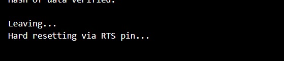
4.6. Successful Programming
Once the code was uploaded, the ESP32-CAM automatically reset, indicating that it was ready for
action.
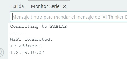
4.7. Connecting to WiFi
The monitor displayed successful connection to the WiFi network, along with the assigned IP address.
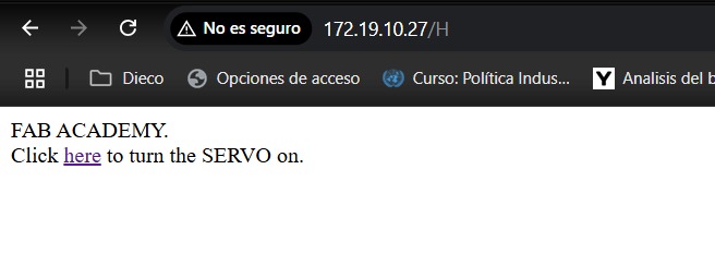
4.8. Accessing the Web Interface
Entering the provided IP address into a web browser displayed a simple webpage with a clickable link
to move the servo motor.
This experience was incredibly rewarding. I was able to wirelessly control a servo motor from my
smartphone through a simple web interface, demonstrating the power and flexibility of the ESP32-CAM.
Setting up the server and seeing the servo respond in real-time was both exciting and motivating,
showcasing how IoT devices can easily interact with the physical world.
Week 11: Conclusion
During Week 11, we successfully explored the fundamentals of networking and communications
applied to embedded systems. Through the group assignment, we learned to design a reliable
wireless communication channel between two ESP32-CAM devices, managing network creation,
server-client architecture, and real-time command exchange using HTTP protocols. Individually,
we expanded our understanding by controlling physical devices remotely, integrating input and
output nodes via WiFi with intuitive web-based interfaces.
This week's experience strengthened our competencies in configuring WiFi-enabled
microcontrollers, building and troubleshooting local networks, and implementing lightweight
communication protocols. It emphasized the importance of stability, latency management, and
feedback validation in interconnected environments. Overall, this foundational work sets the
stage for developing more sophisticated IoT systems and applications, fostering a deeper
technical and practical mastery of device-to-device communication.
Resource Download
Click the button below to access and download all available materials.