
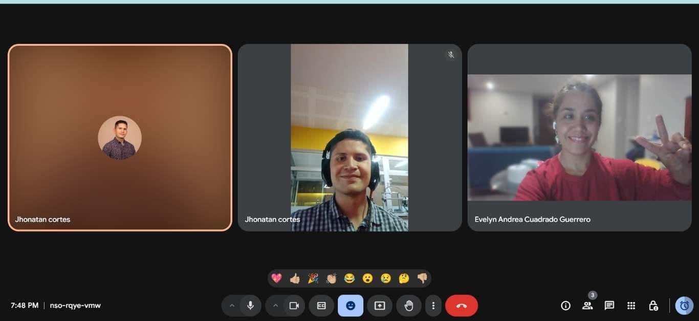
In this project, I teamed up with my partner Jonathan, he from Colombia and I from Peru. Sometimes, the distance seemed like a challenge, but we were able to work efficiently. Especially in this assignment on MQTT, it was very helpful. The technology allowed us to overcome the distance barrier and collaborate seamlessly. This project taught us a lot and showed us how remote connectivity can be used to accomplish complex tasks.
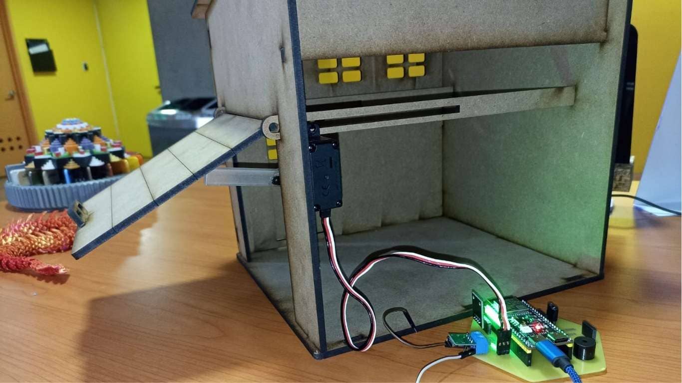
Initially, to avoid simply making a connection between boards, I decided to create a mini project using laser cutting on MDF. In this case, Jhonatan designed a small garage where we installed a servomotor. We had doubts about whether a microservo would be sufficient to lift the structure, so we opted for a 25 kg servomotor to have better control. Additionally, Jhonatan had already planned to control the servomotor from his PCB, so he connected everything from Colombia.
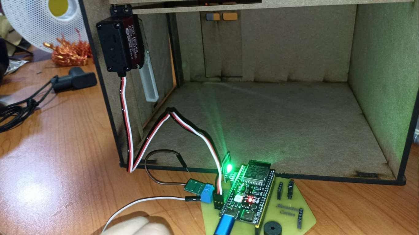
Here we can see more closely the PCB and the circuit Jhonatan has, as it includes several output devices with which we interacted in this exercise, such as the buzzer, the RGB LED, and the servomotor.
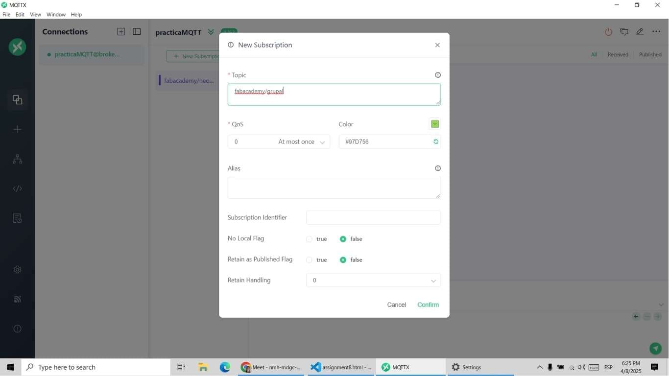
Since we are in different countries, one of the best ways to interconnect was through the Internet. In this case, we used MQTT as a communication tool. So, we created the subscriber Link in MQTTX. To understand how to install, configure, and create it, we reviewed the documentation Evelyn shared with us.
From this program, we validated the correct creation of the topic through which the messages would be sent. We performed some tests by sending messages from each home and verified that they were received correctly. For example, Evelyn sent data from Peru, and in Colombia, it was received without problems.
#include <WiFi.h>           // Include WiFi library (preinstalled for ESP32)
#include <PubSubClient.h>   // Include MQTT client library (install required)

// Wi-Fi credentials
const char* ssid = "CHAYITOS";              // Wi-Fi network name (SSID)
const char* password = "CHIHUAY123";        // Wi-Fi password

// MQTT broker configuration
const char* mqttServer = "broker.emqx.io";  // MQTT broker address
const char* mqttClient = "evkusi";          // MQTT client ID
const char* mqttTopicPub = "fabacademy/grupal"; // MQTT topic to publish messages to

WiFiClient espClient;           // Create a WiFi client
PubSubClient client(espClient); // Create MQTT client using the WiFi client

// Variables for timing and process control
float varNum = 0;
long nowTime, lastTime;

void setup() {
  Serial.begin(115200);               // Start serial communication
  Serial.print("Connecting to ");
  Serial.println(ssid);               // Print SSID being connected to

  WiFi.begin(ssid, password);         // Connect to Wi-Fi

  // Wait until the connection is established
  while (WiFi.status() != WL_CONNECTED) {
    delay(500);
    Serial.print(".");
  }

  Serial.println("");
  Serial.println("Connected with IP ");
  Serial.println(WiFi.localIP());     // Print local IP address

  // Set MQTT server and connect
  client.setServer(mqttServer, 1883); // Set MQTT broker and port
  connectMQTT();                      // Attempt to connect to MQTT broker
}

void connectMQTT() {
  Serial.print("Connecting to MQTT Server ... ");

  if (client.connect(mqttClient)) {
    Serial.println("Connected");      // Successfully connected to MQTT
  } else {
    Serial.print("failed, rc=");
    Serial.print(client.state());     // Print MQTT connection error code
    Serial.println(" try again in 5 seconds");
    delay(5000);                      // Wait before retrying
  }
}

void loop() {
  // Reconnect to MQTT if disconnected
  if (!client.connected()) {
    connectMQTT();
  }

  client.loop();                      // Maintain MQTT connection and handle callbacks

  // Publish "open" to the topic
  client.publish(mqttTopicPub, "open");
  delay(5000);                        // Wait 5 seconds

  // Publish "closed" to the topic
  client.publish(mqttTopicPub, "closed");
  delay(5000);                        // Wait 5 seconds
}
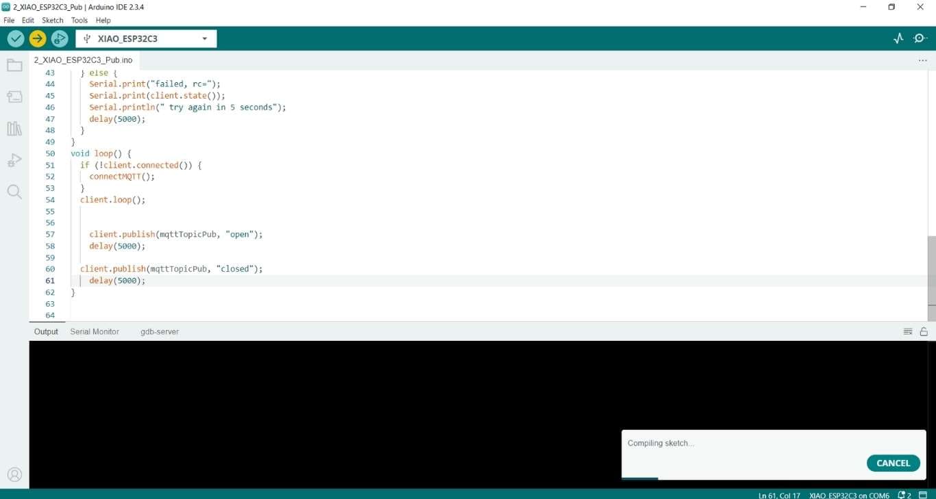
The publisher has a simpler code, with less complexity, as it subscribes to the MQTT topic and, using a millis() process to avoid blocking the board’s execution, sends an "open" or "closed" message every 5 seconds.
Getting into more detail, this publisher was uploaded to a Seeed XIAO ESP32-C3 board, and we can see the Wi-Fi configuration in the first lines of the code.
In the loop part, we used the MQTT function to publish. It is important to note that only text characters can be sent, as it does not accept numbers. After sending the messages, we wait for some time before continuing.
The process is repeated to send the "closed" message and allow the project in Colombia to open or close the garage door.
In the image below, we can see that the code was uploaded to both the ESP32 S3 and the XIAO ESP32-C3, located in different countries. After uploading the code, we proceeded to view the project’s execution on the screen.
                            #include <WiFi.h>         // No install, it's ready
                            #include <PubSubClient.h> // Install library PubSubClient
                            #include <ESP32Servo.h>   // Librería compatible con ESP32 para controlar el servo

                            // Setup your WIFI with SSID/Password
                            const char* ssid = "tatanc";
                            const char* password = "87654321";

                            // Setup your MQTT Protocol
                            const char* mqttServer = "broker.emqx.io";
                            const char* mqttClient = "ESP32C3FacAcademyean007";
                            const char* mqttTopicSub = "fabacademy/grupal";
                            const char* mqttTopicSub2 = "fabacademy/led";
                            WiFiClient espClient;
                            PubSubClient client(espClient);

                            // Setup your process
                            const int servoPin = 14;   // Pin del servo
                            const int buzzerPin = 19;  // Pin del buzzer
                            const int redPin = 5;      // Pin del LED rojo
                            const int greenPin = 4;    // Pin del LED verde
                            const int bluePin = 6;     // Pin del LED azul

                            Servo myServo;  // Crea un objeto servo

                            void setup() {
                              Serial.begin(115200);
                              // Connecting to Wi-Fi
                              Serial.print("Connecting to ");
                              Serial.println(ssid);
                              WiFi.begin(ssid, password);
                              while (WiFi.status() != WL_CONNECTED) {
                                delay(500);
                                Serial.print(".");
                              }
                              Serial.println("");
                              Serial.println("Connected with IP ");
                              Serial.println(WiFi.localIP());

                              // Connecting to MQTT
                              client.setServer(mqttServer, 1883);
                              client.setCallback(callback);
                              connectMQTT();

                              // Setup ESP32 pins
                              pinMode(buzzerPin, OUTPUT);
                              pinMode(redPin, OUTPUT);
                              pinMode(greenPin, OUTPUT);
                              pinMode(bluePin, OUTPUT);

                              // Conectar el servo al pin
                              myServo.attach(servoPin);
                              // Inicializa el LED RGB en azul mientras espera
                              digitalWrite(bluePin, HIGH);
                              digitalWrite(redPin, LOW);  // Apaga el LED rojo
                              digitalWrite(greenPin, LOW); // Apaga el LED verde
                              myServo.write(0);           // Inicia el servo en 0°
                            }

                            void callback(char* topic, byte* message, unsigned int length) {
                              Serial.print("Arrived on ");
                              Serial.print(topic);
                              Serial.print(" with message ");
                              String messageTemp;
                              for (int i = 0; i < length; i++) {
                                Serial.print((char)message[i]);
                                messageTemp += (char)message[i];
                              }
                              Serial.println();

                              if (String(topic) == mqttTopicSub) {
                                if (messageTemp == "closed") {
                                  closedAction();
                                }
                                else if (messageTemp == "open") {
                                  openAction();
                                }
                              }
                            }

                            void openAction() {
                              // Mover el servo gradualmente a 75 grados
                              for (int pos = 0; pos <= 75; pos++) {
                                myServo.write(pos);   // Mueve el servo a la posición 'pos'
                                delay(50);            // Retraso para movimiento gradual
                              }

                              // Emitir un beep gradualmente
                              beepGradual(5);

                              // Encender el LED verde
                              digitalWrite(greenPin, HIGH);
                              digitalWrite(redPin, LOW);  // Apagar el LED rojo
                              digitalWrite(bluePin, LOW); // Apagar el LED azul
                            }

                            void closedAction() {
                              // Emitir un beep continuo
                             for (int i = 0; i < (7*2); i++) {
                                digitalWrite(buzzerPin, HIGH); // Enciende el buzzer
                                delay(100);                    // Beep por 300ms
                                digitalWrite(buzzerPin, LOW);  // Apaga el buzzer
                                delay(100);                    // Espera entre beeps
                              }

                              // Encender el LED rojo
                              digitalWrite(redPin, HIGH);
                              digitalWrite(greenPin, LOW);  // Apagar el LED verde
                              digitalWrite(bluePin, LOW);   // Apagar el LED azul

                              // Mover el servo de vuelta a 0 grados
                              for (int pos = 75; pos >= 0; pos--) {
                                myServo.write(pos);   // Mueve el servo a la posición 'pos'
                                delay(50);            // Retraso para movimiento gradual
                              }
                            }

                            void beepGradual(int times) {
                              for (int i = 0; i < times; i++) {
                                digitalWrite(buzzerPin, HIGH); // Enciende el buzzer
                                delay(300);                    // Beep por 300ms
                                digitalWrite(buzzerPin, LOW);  // Apaga el buzzer
                                delay(300);                    // Espera entre beeps
                              }
                            }

                            void connectMQTT() {
                              Serial.print("Connecting to MQTT Server ... ");
                              if (client.connect(mqttClient)) {
                                Serial.println("Connected");
                                client.subscribe(mqttTopicSub);  // Subscribe to the topic
                              } else {
                                Serial.print("failed, rc=");
                                Serial.print(client.state());
                                Serial.println(" try again in 5 seconds");
                                delay(5000);
                              }
                            }

                            void loop() {
                              if (!client.connected()) {
                                connectMQTT();
                              }
                              client.loop();
                            }
Now, we move on to the process of implementing it on the boards. In this exercise, the publisher is located in Peru, and the subscriber is in Colombia. Below, we can see the code used in more detail. It includes the necessary libraries, first configuring the Wi-Fi network to which the board connects, then the MQTT protocol, and finally defining the pins. What the code really does is simple: it reads what is published on the topic. If the message is "open", it opens the door, emits a sound, and turns on the green light. If it is "closed", it lowers the servomotor. In this case, "open" corresponds to a 75° angle, so it will move to 0°, emit a different beep, and turn on another light.
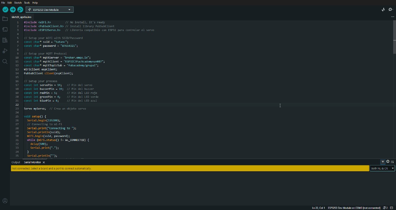
With the code ready, it was uploaded to an ESP32 S3 Devkit located in Bogotá, Colombia.
From Colombia's point of view, we can see on the screen when the "open" message arrives, which opens the door and changes the light, with the same happening for the "closed" message. In both cases, the buzzer emits a completely different beep.
In the next video, we can observe that the actual emitter is a XIAO from another country, sending the instructions. The instructions stop being sent when Evelyn removes the power from the board.
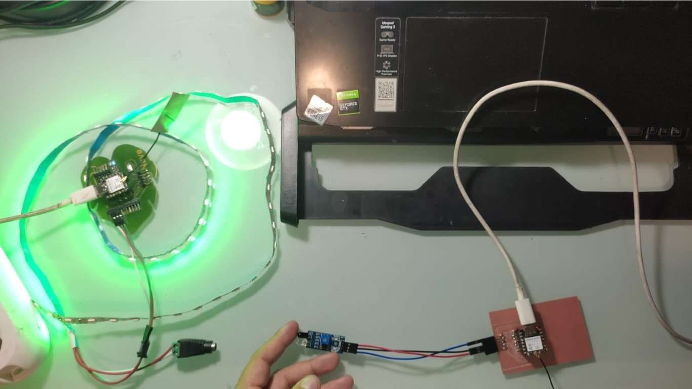
For this project, we will use a Neopixel (or a Neopixel strip), which is a type of addressable LED, meaning each LED on the strip can be controlled independently. We will use a board such as the ESP8266 or ESP32 to connect the Neopixel to a WiFi network, allowing it to be controlled remotely over a wireless connection.
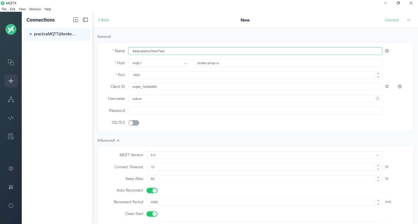
To connect, it is necessary to fill in the general data that are essential for establishing a connection via MQTT. One of the most important parameters is the port, which in this case is 1883. This port is crucial, as it allows communication between devices and ensures that both parties can connect properly. It is important that this data remains consistent so that other users can also connect without issues.
Additionally, by generating a username, we are creating a unique identifier for each user. This username will be used to recognize and authenticate each client that connects to the MQTT server. It is essential that the username is unique and well-managed to avoid connection conflicts.
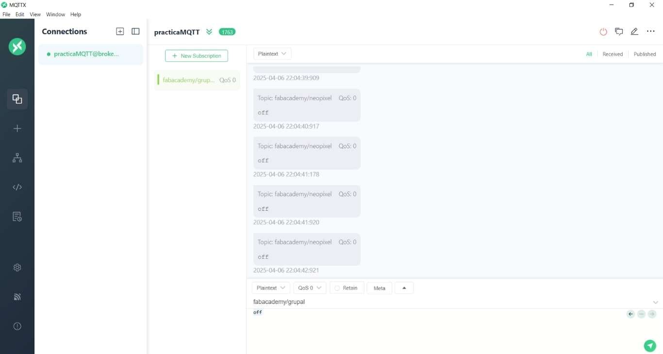
Now, we will subscribe to the topic fabacademy/neopixel. It is crucial that the topic is written correctly, as in MQTT (the messaging protocol), subscribing to the topic is case-sensitive. This means that if we write the topic incorrectly, such as FabAcademy/NeoPixel or FABACADEMY/NEOPIXEL, it will not work properly because the MQTT server expects the topic to be written exactly as it is defined. Therefore, we need to ensure the topic is written correctly: fabacademy/neopixel.
#include <WiFi.h>          // Librería WiFi
#include <PubSubClient.h>  // Librería para el protocolo MQTT

// Configuración WiFi
const char* ssid = "tatanc";
const char* password = "87654321";

// Configuración MQTT
const char* mqttServer = "broker.emqx.io";
const char* mqttClient = "ESP32C3FacAcademyean007";
const char* mqttTopicPub = "fabacademy/neopixel"; // Tema de publicación
WiFiClient espClient;
PubSubClient client(espClient);

// Variables para el control de tiempo y estados
int varNum = 0;
long nowTime, lastTime;
String status = "off";  // Estado inicial del LED
bool lastTouchState = LOW; // Estado anterior del sensor táctil
bool currentTouchState = LOW; // Estado actual del sensor táctil

void setup() {
  Serial.begin(115200);

  // Conectar a WiFi
  Serial.print("Conectando a WiFi ");
  WiFi.begin(ssid, password);
  while (WiFi.status() != WL_CONNECTED) {
    delay(500);
    Serial.print(".");
  }
  Serial.println(" Conectado");
  Serial.println("IP: " + WiFi.localIP().toString());

  // Conectar a MQTT
  client.setServer(mqttServer, 1883);
  connectMQTT();

  // Configurar pin del sensor táctil
  pinMode(2, INPUT);  // Suponiendo que el pin 2 es el sensor táctil
}

void connectMQTT() {
  Serial.print("Conectando a servidor MQTT ... ");
  while (!client.connected()) {
    if (client.connect(mqttClient)) {
      Serial.println("Conectado");
    } else {
      Serial.print("fallo, rc=");
      Serial.print(client.state());
      Serial.println(" Reintentando en 5 segundos");
      delay(5000);
    }
  }
  client.subscribe(mqttTopicPub); // Suscribirse al tema (si es necesario)
}

void loop() {
  if (!client.connected()) {
    connectMQTT();
  }
  client.loop();

  // Leer el valor del sensor táctil
  currentTouchState = digitalRead(2); // Se usa el pin 2 para el sensor táctil

  // Detectar si el sensor táctil ha cambiado de estado
  if (currentTouchState == HIGH && lastTouchState == LOW) {
    // Si el sensor táctil fue presionado
    if (status == "off") {
      // Si el LED está apagado, encenderlo
      Serial.println("LED ON");
      client.publish(mqttTopicPub, "on");  // Publicar estado "on"
      status = "on";  // Cambiar el estado a "on"
    } else {
      // Si el LED está encendido, apagarlo
      Serial.println("LED OFF");
      client.publish(mqttTopicPub, "off");  // Publicar estado "off"
      status = "off";  // Cambiar el estado a "off"
    }
    delay(500);  // Esperar medio segundo para evitar lecturas múltiples por un solo toque
  }

  lastTouchState = currentTouchState;  // Guardar el estado actual del sensor táctil

  delay(100);  // Espera de 100 ms para el siguiente ciclo
}
Now, for the publisher, a similar configuration was done as for the subscriber, with the difference that key parameters, such as the WiFi settings and the MQTT client, were modified. These changes are essential for the device to publish messages instead of receiving them via MQTT.
#include <WiFi.h>         // No installation needed, it’s ready for ESP32
#include <PubSubClient.h> // Install PubSubClient library for MQTT
#include <Adafruit_NeoPixel.h> // Install Adafruit NeoPixel library

// Setup your WIFI with SSID/Password
const char* ssid = "CHAYITOPOWER";        // Wi-Fi network name (SSID)
const char* password = "CHIHUAY123";      // Wi-Fi network password

// Setup your MQTT Protocol
const char* mqttServer = "broker.emqx.io";  // MQTT broker address
const char* mqttClient = "evkusi";          // MQTT client ID
const char* mqttTopicSub = "fabacademy/neopixel"; // MQTT topic for subscribing
WiFiClient espClient;
PubSubClient client(espClient);

// Setup NeoPixel Pin
#define PIN            A0  // Data pin to which the NeoPixel strip is connected
#define NUM_PIXELS     30 // Number of LEDs in the strip (adjust to your needs)
#define BRIGHTNESS     255 // Maximum brightness (you can adjust this value)
Adafruit_NeoPixel strip(NUM_PIXELS, PIN, NEO_GRB + NEO_KHZ800);

// Variable to handle MQTT messages
String mqttMessage = "";

void setup() {
  Serial.begin(115200);

  // Connecting to Wifi
  Serial.print("Connecting to ");
  Serial.println(ssid);
  WiFi.begin(ssid, password);
  while (WiFi.status() != WL_CONNECTED) {
    delay(500);
    Serial.print(".");
  }
  Serial.println("");
  Serial.println("Connected with IP ");
  Serial.println(WiFi.localIP());

  // Setup MQTT
  client.setServer(mqttServer, 1883);
  client.setCallback(callback);

  // Initial connection to MQTT
  connectMQTT();

  // Setup NeoPixel
  strip.begin();
  strip.show();  // Turn off all LEDs initially
}

void callback(char* topic, byte* message, unsigned int length) {
  String messageTemp = "";
  for (int i = 0; i < length; i++) {
    messageTemp += (char)message[i];
  }

  // Print the received MQTT message
  Serial.print("Arrived on ");
  Serial.print(topic);
  Serial.print(" the message ");
  Serial.println(messageTemp);

  // Store the message to process in the loop
  mqttMessage = messageTemp;

  // Control the LEDs based on the received MQTT message
  if (String(topic) == mqttTopicSub) {
    if (mqttMessage == "on") {
      strip.fill(strip.Color(0, 255, 0)); // Green
      strip.show();
    }
    else if (mqttMessage == "off") {
      strip.fill(strip.Color(0, 0, 0));  // Turn off
      strip.show();
    }
    else if (mqttMessage == "random") {
      setRandomColor(); // Set random color
    }
  }
}

void connectMQTT() {
  // Keep trying to connect to the MQTT server if not connected
  while (!client.connected()) {
    Serial.print("Connecting to MQTT Server... ");
    if (client.connect(mqttClient)) {
      Serial.println("Connected");
      // Subscribe to the MQTT topic
      client.subscribe(mqttTopicSub);
    } else {
      Serial.print("Failed, rc=");
      Serial.print(client.state());
      Serial.println(" Try again in 5 seconds");
      delay(5000);
    }
  }
}

void loop() {
  if (!client.connected()) {
    connectMQTT(); // Ensure we're connected to MQTT
  }
  client.loop();  // Process incoming messages and maintain the connection
}

// Function to set a random color to all NeoPixels
void setRandomColor() {
  for (int i = 0; i < strip.numPixels(); i++) {
    // Generate random values for red, green, and blue (from 0 to 255)
    int red = random(0, 256);
    int green = random(0, 256);
    int blue = random(0, 256);

    // Set the color of each LED with the random values
    strip.setPixelColor(i, strip.Color(red, green, blue));
  }
  strip.show(); // Update the strip with the new colors
}
As a subscriber, you need to have a code that allows you to connect to the MQTT server and receive messages from the desired topic. A crucial aspect of this process is the connection to the local network, as we need to be connected to a WiFi network in order to interact with the MQTT server. To do this, you must provide the network password to gain access.
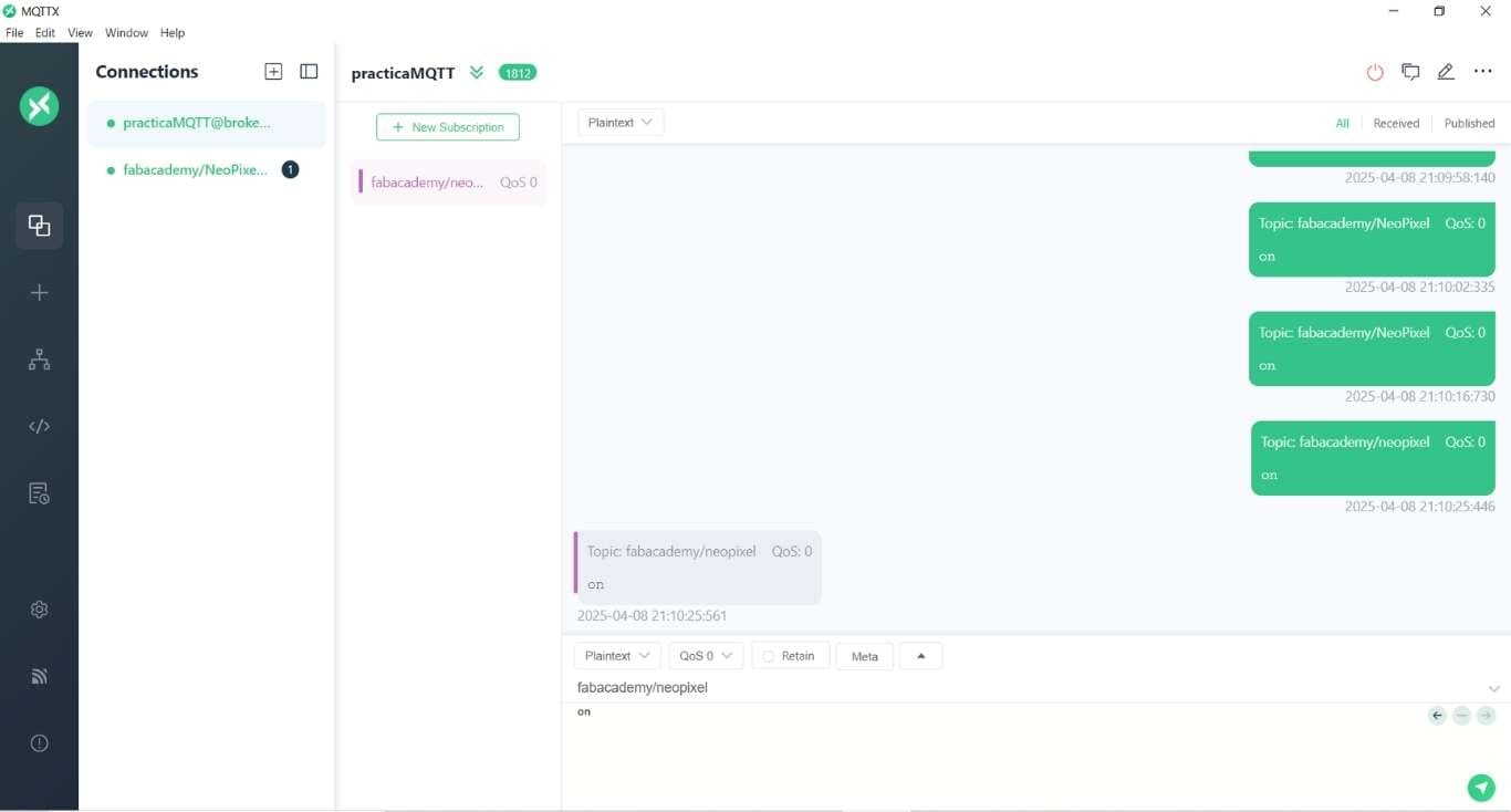
As an MQTT client, the device (in this case, the EVKUSI) will connect to the server with the necessary credentials (such as username and password), and then subscribe to the specific topic, in this case, fablab/neopixel. By subscribing to this topic, the client will be able to receive messages published under that topic.
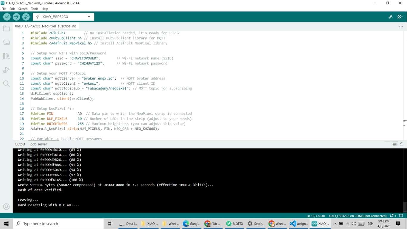
In the Arduino IDE, after preparing the code to connect the device to the MQTT server, you need to perform key configurations:
In the results, we can see the successful connection via MQTT, even though my partner is kilometers away, specifically in Colombia, while I am in Peru. However, this challenge can be carried out without complications. As a publisher, he can send his sensor data and control the turning on and off of the LED remotely.
In this result, another function of the NeoPixel can be verified, which allows the colors of the LED strip to change dynamically. By using the random keyword, the colors were generated randomly. Every time the random function was called again, the colors would change unpredictably, creating surprising visual effects.
The objective of this group assignment for Week 11 was to demonstrate communication between two separate projects using networking protocols. Specifically, we were required to send a message from one board to another and document the process and results as a team.
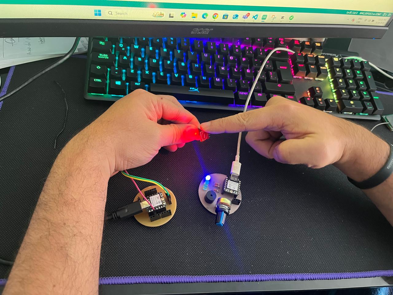
For our project, we used two XIAO ESP32 C3 boards. The first board, managed by Andru, acts as the sender: every time a touch sensor connected to pin D2 is activated, it sends a message over WiFi using the MQTT protocol. The second board, managed by Michael, serves as the receiver: it listens for incoming messages and controls three LEDs (blue on D2, yellow on D3, and green on D4), lighting them up in sequence for each received message and resetting after three.
This collaborative task allowed us to explore MQTT-based communication, practical networking, and teamwork in an embedded systems context. Below, we document our process, results, and reflections.
The following materials and hardware components were used to build and test the group assignment:
| Component | Quantity | Details |
|---|---|---|
| XIAO ESP32 C3 board | 2 | Microcontroller board for both sender and receiver |
| Touch sensor | 1 | Connected to D2 on the sender board (Andru) |
| LED (Blue) | 1 | Connected to D2 on the receiver board (Michael) |
| LED (Yellow) | 1 | Connected to D3 on the receiver board (Michael) |
| LED (Green) | 1 | Connected to D4 on the receiver board (Michael) |
| Resistors (220Ω) | 3 | For limiting current to LEDs |
The communication between both boards was established using WiFi and the MQTT protocol. Below are the key network settings and parameters used for the assignment:
FabAcademy/week11FabAcademy_Colombia_ANDRU (Sender)FabAcademy_Colombia_MICHAEL (Receiver)
Both boards were configured with these settings to ensure reliable communication throughout the testing
process. The broker broker.emqx.io was chosen for its ease of use and availability for public
MQTT testing.
The sender board uses a XIAO ESP32 C3 connected to a capacitive touch sensor on pin D2. Each time the sensor
detects a touch event, the board sends a "TOUCH" message to the MQTT topic FabAcademy/week11
via WiFi.
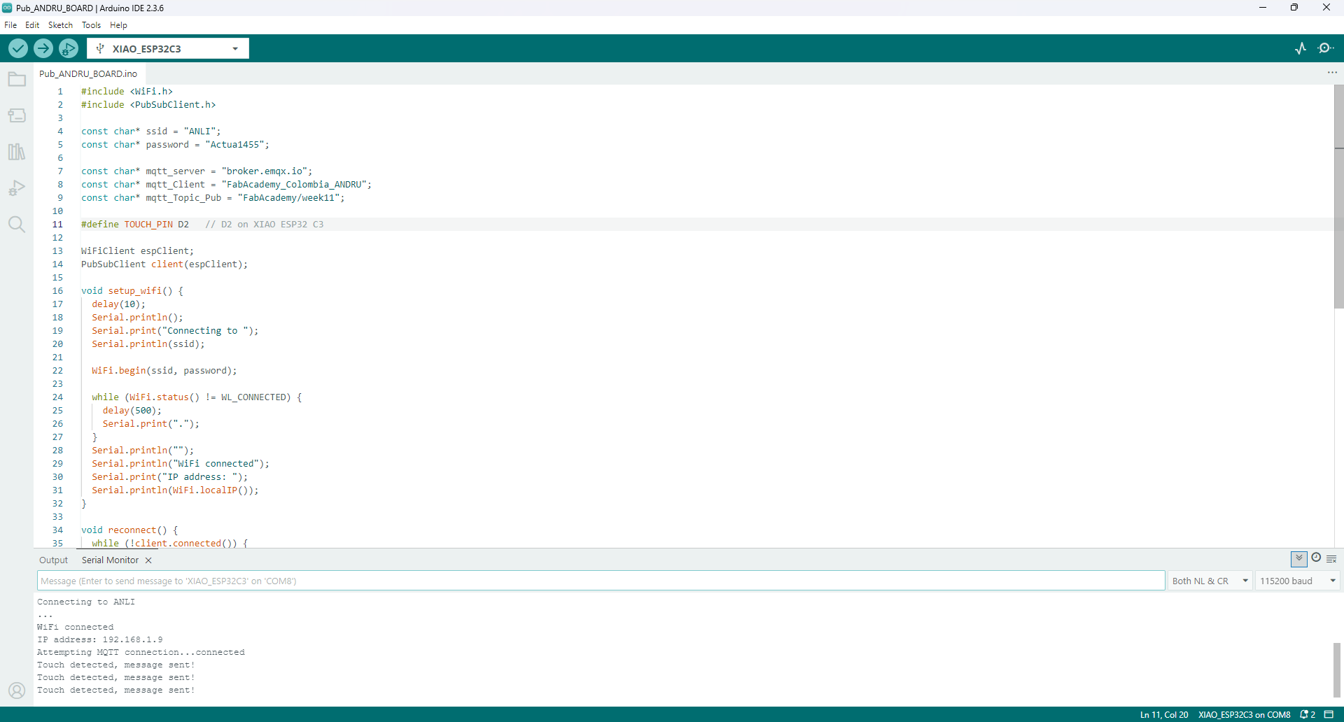
The following Arduino code was used on the sender board:
            #include <WiFi.h>
            #include <PubSubClient.h>

            const char* ssid = "ANLI";
            const char* password = "Actua1455";

            const char* mqtt_server = "broker.emqx.io";
            const char* mqtt_Client = "FabAcademy_Colombia_ANDRU";
            const char* mqtt_Topic_Pub = "FabAcademy/week11";

            #define TOUCH_PIN D2   // D2 on XIAO ESP32 C3

            WiFiClient espClient;
            PubSubClient client(espClient);

            void setup_wifi() {
            delay(10);
            Serial.println();
            Serial.print("Connecting to ");
            Serial.println(ssid);

            WiFi.begin(ssid, password);

            while (WiFi.status() != WL_CONNECTED) {
                delay(500);
                Serial.print(".");
            }
            Serial.println("");
            Serial.println("WiFi connected");
            Serial.print("IP address: ");
            Serial.println(WiFi.localIP());
            }

            void reconnect() {
            while (!client.connected()) {
                Serial.print("Attempting MQTT connection...");
                if (client.connect(mqtt_Client)) {
                Serial.println("connected");
                } else {
                Serial.print("failed, rc=");
                Serial.print(client.state());
                Serial.println(" try again in 5 seconds");
                delay(5000);
                }
            }
            }

            void setup() {
            Serial.begin(115200);
            pinMode(TOUCH_PIN, INPUT);
            setup_wifi();
            client.setServer(mqtt_server, 1883);
            }

            void loop() {
            if (!client.connected()) {
                reconnect();
            }
            client.loop();

            int touchValue = digitalRead(TOUCH_PIN);
            static bool lastTouch = false;

            if (touchValue == HIGH && !lastTouch) {
                client.publish(mqtt_Topic_Pub, "TOUCH");
                Serial.println("Touch detected, message sent!");
                lastTouch = true;
                delay(300); // debounce
            } else if (touchValue == LOW) {
                lastTouch = false;
            }
            }
The receiver board is also a XIAO ESP32 C3, with three LEDs connected to pins D2 (blue), D3 (yellow), and D4 (green). This board subscribes to the same MQTT topic and listens for incoming "TOUCH" messages.
FabAcademy/week11For each received message, the board lights up the corresponding LED in sequence (blue → yellow → green), and after the third message, the cycle restarts by turning all LEDs off and beginning again.
            #include <WiFi.h>
            #include <PubSubClient.h>

            const char* ssid = "ANLI";
            const char* password = "Actua1455";

            const char* mqtt_server = "broker.emqx.io";
            const char* mqtt_Client = "FabAcademy_Colombia_MICHAEL";
            const char* mqtt_Topic_Sub = "FabAcademy/week11";

            #define LED_BLUE D2     // D2 on XIAO ESP32 C3
            #define LED_YELLOW D3   // D3
            #define LED_GREEN D4    // D4

            WiFiClient espClient;
            PubSubClient client(espClient);

            int counter = 0;

            void setup_wifi() {
            delay(10);
            Serial.println();
            Serial.print("Connecting to ");
            Serial.println(ssid);

            WiFi.begin(ssid, password);

            while (WiFi.status() != WL_CONNECTED) {
                delay(500);
                Serial.print(".");
            }
            Serial.println("");
            Serial.println("WiFi connected");
            Serial.print("IP address: ");
            Serial.println(WiFi.localIP());
            }

            void turnOffAll() {
            digitalWrite(LED_BLUE, LOW);
            digitalWrite(LED_YELLOW, LOW);
            digitalWrite(LED_GREEN, LOW);
            }

            void showLED(int count) {
            turnOffAll();
            if (count == 1) digitalWrite(LED_BLUE, HIGH);
            else if (count == 2) digitalWrite(LED_YELLOW, HIGH);
            else if (count == 3) digitalWrite(LED_GREEN, HIGH);
            }

            void callback(char* topic, byte* payload, unsigned int length) {
            String msg;
            for (unsigned int i = 0; i < length; i++) {
                msg += (char)payload[i];
            }
            if (msg == "TOUCH") {
                counter++;
                if (counter > 3) counter = 1;
                showLED(counter);
                Serial.print("TOUCH message received. LED: ");
                Serial.println(counter);
            }
            }

            void reconnect() {
            while (!client.connected()) {
                Serial.print("Attempting MQTT connection...");
                if (client.connect(mqtt_Client)) {
                Serial.println("connected");
                client.subscribe(mqtt_Topic_Sub);
                } else {
                Serial.print("failed, rc=");
                Serial.print(client.state());
                Serial.println(" try again in 5 seconds");
                delay(5000);
                }
            }
            }

            void setup() {
            Serial.begin(115200);
            pinMode(LED_BLUE, OUTPUT);
            pinMode(LED_YELLOW, OUTPUT);
            pinMode(LED_GREEN, OUTPUT);
            turnOffAll();
            setup_wifi();
            client.setServer(mqtt_server, 1883);
            client.setCallback(callback);
            }

            void loop() {
            if (!client.connected()) {
                reconnect();
            }
            client.loop();
            }
Complete source codes are also available for download in the Downloads section.
To verify the correct operation of the system, we performed several tests involving both the sender (Andru’s board) and receiver (Michael’s board). The process consisted of activating the touch sensor and observing the LED sequence on the receiver.
The MQTT subscription and communication channel were configured in advance to ensure smooth interaction between the two boards. Full details of the broker setup, topic selection, and testing process are documented on Andrés Felipe Guarnizo’s individual Week 11 assignment page.
To verify message delivery, we monitored the MQTT broker dashboard. The image below shows the broker successfully receiving the word "TOUCH" each time the touch sensor was activated.
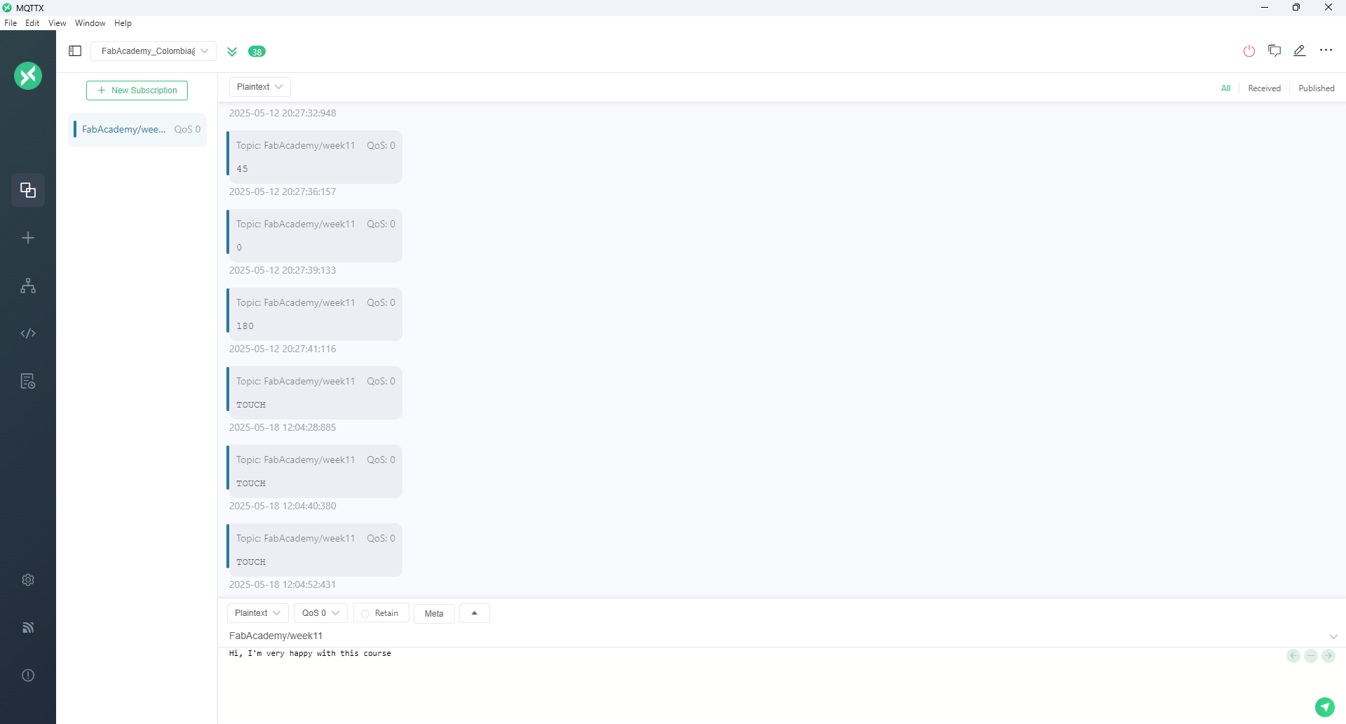
This successful test demonstrates reliable networking between embedded devices using MQTT and validates our design approach for real-world IoT scenarios.
All resources required to replicate this group assignment are available for download below:
Please feel free to use and adapt these resources for educational purposes. For more details, refer to the individual documentation pages of the team members.
Team: Manuel Ayala-Chauvin, Sandra Nuñez-Torres
Institution: Fablab - Universidad Tecnológica Indoamérica
Year: 2025
The goal of this project was to design, build, and connect wired or wireless nodes with network or bus addresses, integrating local input and/or output devices to simulate a basic Internet of Things (IoT) interaction between two embedded systems.
For this assignment, we implemented a communication system using two ESP32-CAM modules. Each device was independently powered and equipped with WiFi capabilities, allowing them to interact through a local wireless network. A crucial feature of the ESP32-CAM is the onboard LED connected to GPIO4, which was leveraged to visually confirm the successful transmission and reception of commands between devices.
Each ESP32-CAM module was mounted on a breadboard and connected to its respective power source. Basic pin configurations were completed, including preparing a push button circuit for the client device to trigger HTTP requests.
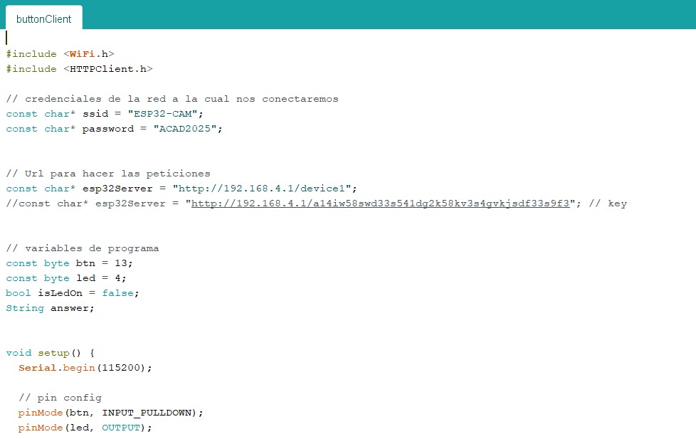
					#include
#include

// credenciales de la red a la cual nos conectaremos
const char* ssid = "ESP32-CAM";
const char* password = "ACAD2025";

// Url para hacer las peticiones
const char* esp32Server = "http://192.168.4.1/device1";
//const char* esp32Server = "http://192.168.4.1/a14iw58swd33s541dq2k58kx3s4qvkj..."; // key

// variables de programa
const byte btn = 13;
const byte led = 4;
bool isLedOn = false;
String answer;

void setup() {
  Serial.begin(115200);

  // pin config
  pinMode(btn, INPUT_PULLDOWN);
  pinMode(led, OUTPUT);
We configured a local WiFi network using a mobile hotspot or router. One ESP32-CAM was programmed to operate as a server, constantly listening for HTTP requests, while the other functioned as a client capable of sending HTTP requests to the server's IP address whenever the button was pressed.

Both ESP32-CAM boards were programmed with the WiFi credentials of the newly created network. The server board printed its local IP address upon successful connection, which was noted and programmed into the client board for precise targeting of HTTP requests.
// nos conectamos a la red
WiFi.begin(ssid, password);
Serial.println("Connecting");
while (WiFi.status() != WL_CONNECTED) {
delay(500);
Serial.print(".");
}
Serial.println("");
Serial.print("Conectado a la red con la IP: ");
Serial.println(WiFi.localIP());
Serial.println();
}
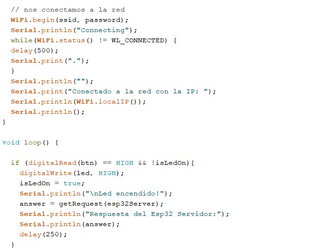
void loop() {
if (digitalRead(btn) == HIGH && !isLedOn) {
digitalWrite(led, HIGH);
isLedOn = true;
Serial.println("\nLed encendido!");
answer = getRequest(esp32Server);
Serial.println("Respuesta del Esp32 Servidor:");
Serial.println(answer);
delay(250);
}
After successful network connection, the client ESP32-CAM continuously monitored the state of the push button. When the button was pressed, it sent an HTTP GET request to the server ESP32-CAM. Upon receiving a request, the server toggled its onboard LED state (turning it ON or OFF) depending on the instruction received, providing immediate visual feedback of communication success.
Care was taken to implement debounce delays in the button reading to ensure accurate and reliable operation. Additionally, the HTTP response code and payload were printed on the serial monitor for debugging and verification purposes.
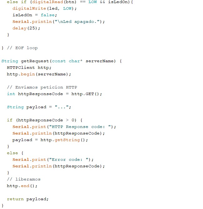
					  else if (digitalRead(btn) == LOW && isLedOn) {
    digitalWrite(led, LOW);
    isLedOn = false;
    Serial.println("\nLed apagado.");
    delay(25);
  }
} // EOF loop

String getRequest(const char* serverName) {
  HTTPClient http;
  http.begin(serverName);

  // Enviamos peticion HTTP
  int httpResponseCode = http.GET();

  String payload = "...";

  if (httpResponseCode > 0) {
    Serial.print("HTTP Response code: ");
    Serial.println(httpResponseCode);
    payload = http.getString();
  }
  else {
    Serial.print("Error code: ");
    Serial.println(httpResponseCode);
  }

  // liberamos
  http.end();

  return payload;
}
Server-side: Listened for incoming HTTP GET requests and toggled the LED accordingly. The server also responded with an acknowledgment message back to the client.
Client-side: Continuously monitored the push button. Upon detecting a press, it sent a GET request to the server and processed the server's response, printing it to the serial monitor for confirmation.
This group project offered an invaluable opportunity to delve into basic IoT communication between two embedded devices using WiFi. By building both the server and client logic, we gained a practical understanding of wireless networking protocols, HTTP communication, and microcontroller programming. The real-time LED response upon request provided immediate feedback that not only confirmed the success of our setup but also reinforced the importance of careful configuration and debugging in networked systems. This foundational exercise prepares us for more complex interconnected systems in future smart device applications.
The objective of this task was to establish MQTT communication between two independent microcontroller systems in order to control a DC motor based on sensor readings. The system uses an ESP32 DevKit v1 to publish messages from an ultrasonic distance sensor, and an ESP32-C3 Xiao to subscribe and control a DC motor accordingly.
broker.emqx.io
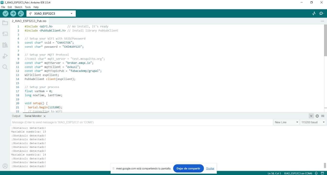
The ESP32 DevKit v1 was connected to an HC-SR04 ultrasonic sensor. It continuously measures the distance to nearby objects. When an object is detected within 20 cm, it publishes a message "adelante" (forward) to the MQTT topic motor/control. If the area is clear, it publishes "stop".
The ESP32-C3 Xiao subscribes to the same topic. Upon receiving a message, it interprets the command and actuates the DC motor:
Both codes were uploaded using the Arduino IDE. After connecting both boards to the same Wi-Fi network, the communication was established through the MQTT broker. The system was tested by placing objects in front of the sensor and observing the motor behavior in response. It responded correctly to each command. One initial issue encountered was related to power stability on the motor side, which was resolved by providing a separate power source for the motor driver.
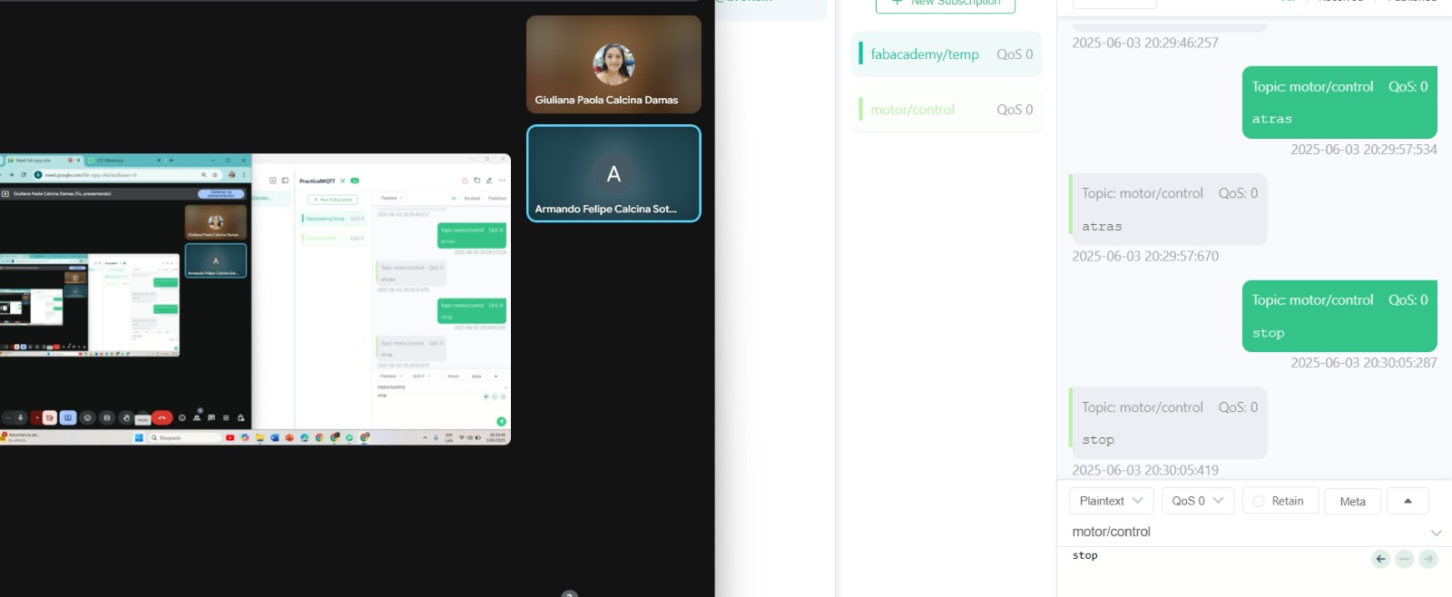
To develop this exercise, I enlisted the help of another person who sent the messages from a different device. The messages were successfully received through the MQTT platform, allowing the corresponding actions to be executed in the engine based on each command.
#include <WiFi.h>
#include <PubSubClient.h>

const char* ssid = "ALBER 2.4G";
const char* password = "asrael2050";

const char* mqtt_server = "broker.emqx.io";
const int mqtt_port = 1883;
const char* topic = "motor/control";

WiFiClient espClient;
PubSubClient client(espClient);

// Pines del sensor
const int trigPin = 5;
const int echoPin = 18;

void setup_wifi() {
  WiFi.begin(ssid, password);
  while (WiFi.status() != WL_CONNECTED) {
    delay(500);
  }
}

void setup() {
  Serial.begin(115200);
  pinMode(trigPin, OUTPUT);
  pinMode(echoPin, INPUT);

  setup_wifi();
  client.setServer(mqtt_server, mqtt_port);
}

void loop() {
  if (!client.connected()) {
    while (!client.connected()) {
      client.connect("ESP32-Sensor");
    }
  }

  client.loop();

  // Medir distancia
  digitalWrite(trigPin, LOW);
  delayMicroseconds(2);
  digitalWrite(trigPin, HIGH);
  delayMicroseconds(10);
  digitalWrite(trigPin, LOW);

  long duration = pulseIn(echoPin, HIGH);
  float distance = duration * 0.034 / 2;

  Serial.print("Distancia: ");
  Serial.println(distance);

  if (distance < 20.0) {
    client.publish(topic, "adelante");
  } else {
    client.publish(topic, "stop");
  }

  delay(1000);
}
#include <WiFi.h>
#include <PubSubClient.h>

const int IN1 = 2;
const int IN2 = 4;

const char* ssid = "ALBER 2.4G";
const char* password = "asrael2050";

const char* mqtt_server = "broker.emqx.io";
const int mqtt_port = 1883;
const char* topic = "motor/control";

WiFiClient espClient;
PubSubClient client(espClient);

void callback(char* topic, byte* payload, unsigned int length) {
  String msg;
  for (int i = 0; i < length; i++) {
    msg += (char)payload[i];
  }
  msg.trim();

  if (msg == "adelante") {
    digitalWrite(IN1, HIGH);
    digitalWrite(IN2, LOW);
  } else if (msg == "stop") {
    digitalWrite(IN1, LOW);
    digitalWrite(IN2, LOW);
  }
}

void reconnect() {
  while (!client.connected()) {
    if (client.connect("ESP32-Motor")) {
      client.subscribe(topic);
    } else {
      delay(2000);
    }
  }
}

void setup() {
  Serial.begin(115200);
  pinMode(IN1, OUTPUT);
  pinMode(IN2, OUTPUT);

  WiFi.begin(ssid, password);
  while (WiFi.status() != WL_CONNECTED) {
    delay(500);
  }

  client.setServer(mqtt_server, mqtt_port);
  client.setCallback(callback);
}

void loop() {
  if (!client.connected()) {
    reconnect();
  }
  client.loop();
}
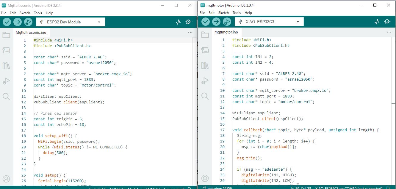
Description of the loaded codes
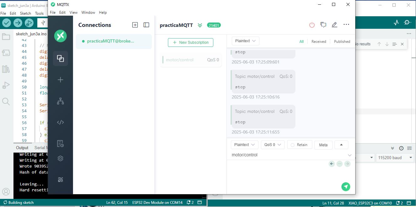
MQTT Communication Overview
This image illustrates the two ESP32 devices running their respective codes and communicating via MQTT. The ESP32 DevKit v1 reads distance data from the ultrasonic sensor and publishes control messages (“forward” or “stop”) to the MQTT broker. The ESP32-C3 Xiao subscribes to these messages and controls the DC motor accordingly, demonstrating real-time wireless communication and control.
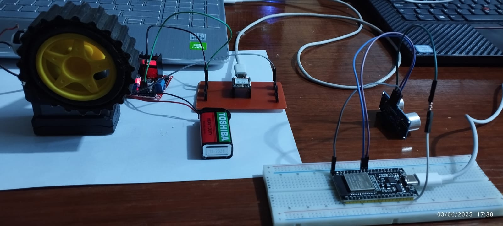
System Setup with Microcontrollers and Sensors
The image shows both microcontrollers in the project: the ESP32 DevKit v1 connected to the ultrasonic sensor, and the ESP32-C3 Xiao connected to the DC motor. Each device runs its respective code to publish and subscribe MQTT messages, enabling wireless communication and coordinated control between sensor input and motor output.
In this project, two ESP32 microcontrollers successfully communicated effectively using the MQTT protocol to control a DC motor based on readings from an ultrasonic sensor. The ESP32 DevKit v1 board acts as the publisher, sending messages based on the detected distance, while the ESP32-C3 Xiao acts as the subscriber, interpreting these messages to control the motor. This exercise provided insight into the importance of wireless communication in distributed embedded systems, the configuration and management of a public MQTT broker, and the integration of sensors and actuators in real time. It also highlighted the need for adequate power to ensure system stability. The experience strengthened practical skills in programming, networking, and hardware control, which are essential for automation and robotics projects.