Measure the power consumption of an output device.
Document your work on the group work page and reflect on your individual page what
you learned.
Individual Assignment
Add an output device to a microcontroller board you've designed and program it to do
something.
Manuel Ayala-Chauvin Institution: Fablab - Universidad Tecnológica Indoamérica Year: 2025
Group Assignment 10: Measurement of Power Consumption of an Output Device
Team: Manuel Ayala-Chauvin, Sandra Nuñez-Torres Institution: Fablab - Universidad Tecnológica Indoamérica Year: 2025
Output Device Selected
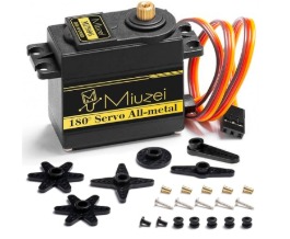
For this assignment, we selected a servo motor model MZ996. This type of servo is
commonly used in electronic projects due to its metal gears, which offer better
resistance and durability during mechanical movements.
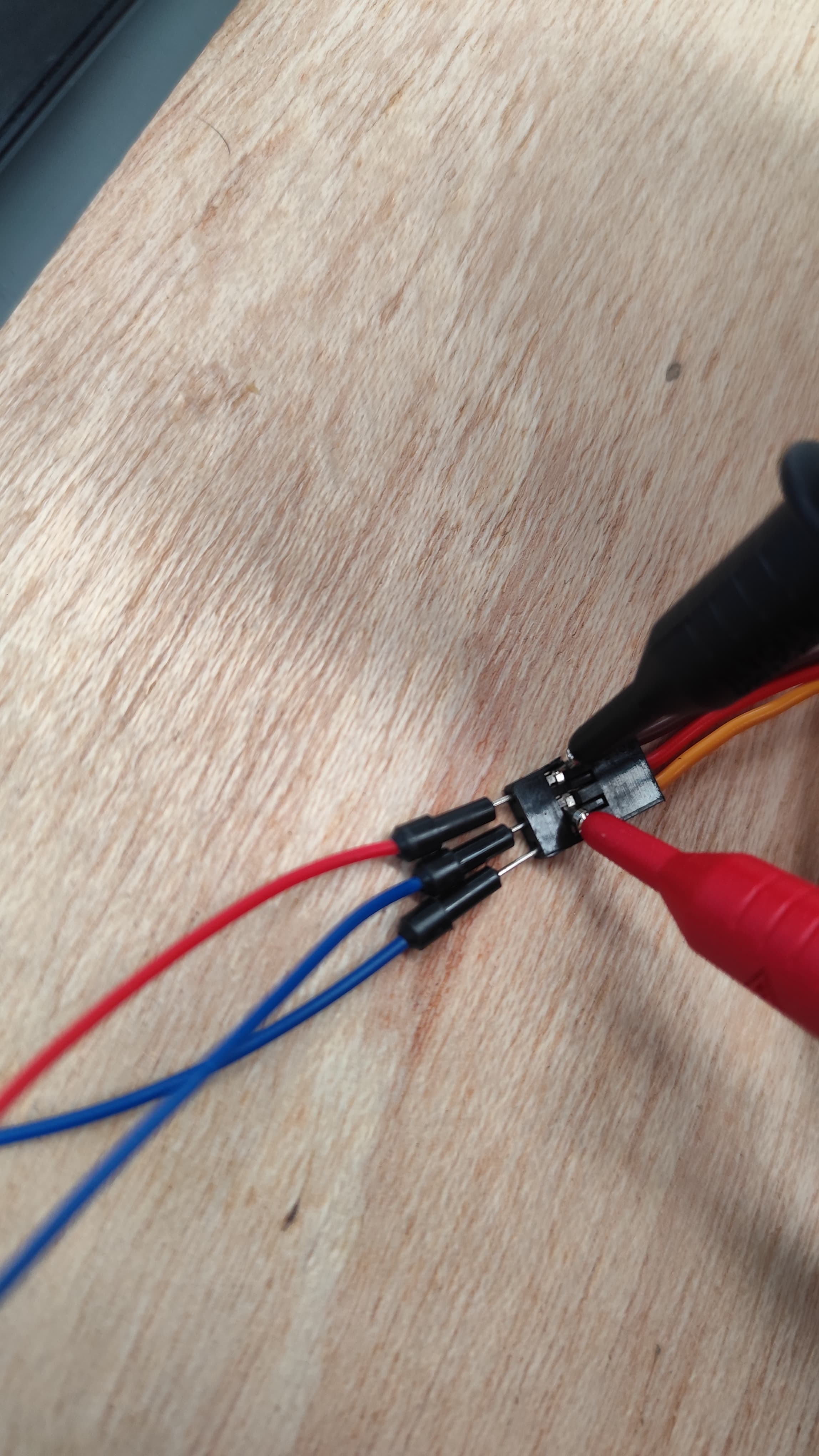
Connection Setup
The servo motor has three wires:
VCC (red) – connected to 5V DC power supply.
GND (black or brown) – connected to ground.
Signal (orange or yellow) – connected to a PWM output of the development board
(e.g., Arduino).
The servo is controlled using a PWM signal and operates at 5V DC.
Since the servo was not under load (not moving any external weight), the
current consumption remained low and stable.
Conclusion
The measurement of power consumption showed that:
The voltage remained around 5V with minor fluctuations.
The current draw was minimal, which aligns with the unloaded condition of the motor.
Proper use of the multimeter (parallel for voltage, series for current) is essential for
accurate power measurements.
In this assignment, an output device was added to a previously designed and fabricated development
board using an ATTINY412 microcontroller. The chosen output devices were two servo motors, which
were controlled through programming using the developed board.
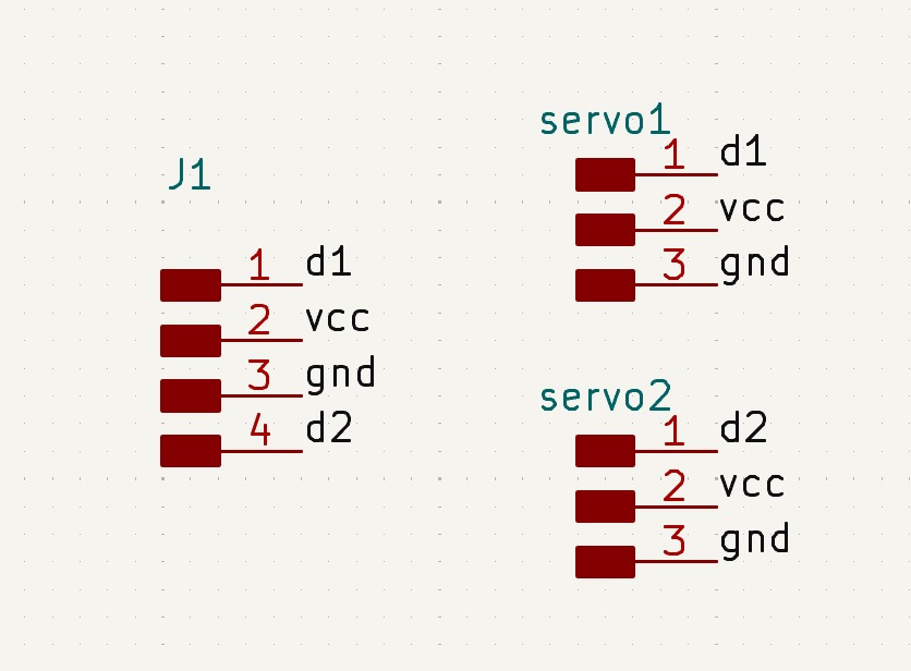
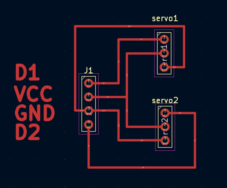
Step 1: Electronic Schematic Design
Initially, an electronic schematic was created considering the devices to be connected. Each servo
motor includes three pins: VCC (power), GND (ground), and a control signal that enables its
movement. The initial schematic diagram is shown below:
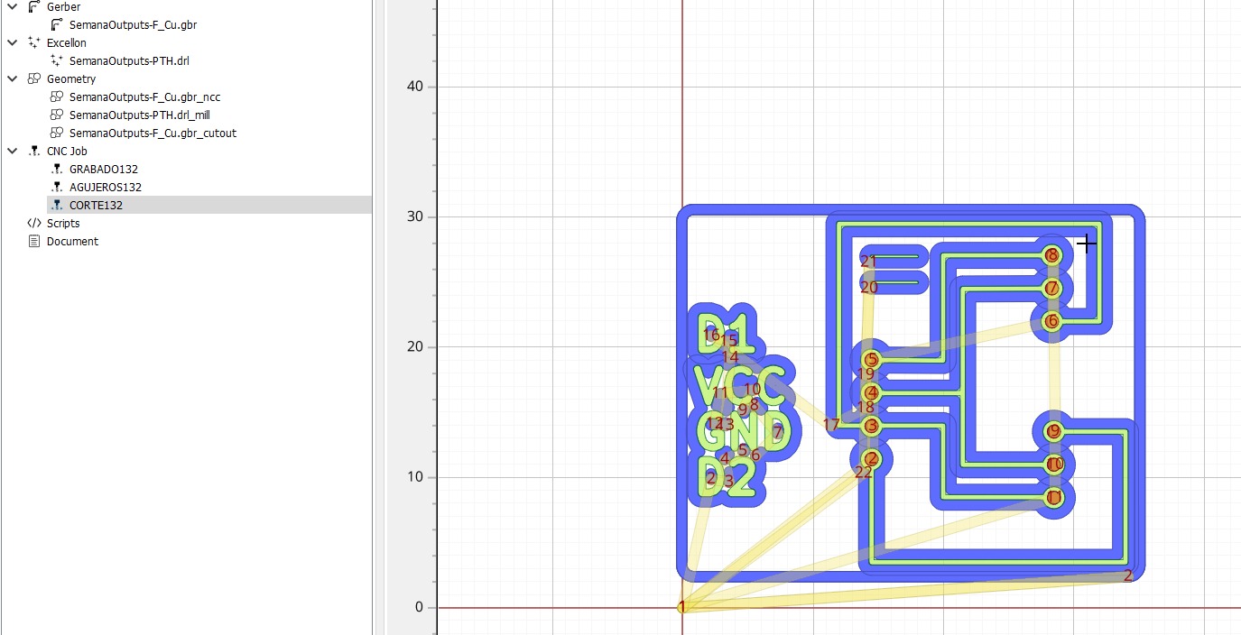
Step 2: PCB Design
After defining the schematic, the printed circuit board (PCB) was designed. This process carefully
organized connections to ensure both servo motors were powered through a single connection,
facilitating the necessary control signals from the microcontroller.
Step 3: Gerber File Generation and Configuration
From the PCB design, Gerber files detailing electrical paths and required drillings were generated.
These files were configured and subsequently converted into G-code format, ready for use on the
Monofab SRM-20 milling machine.
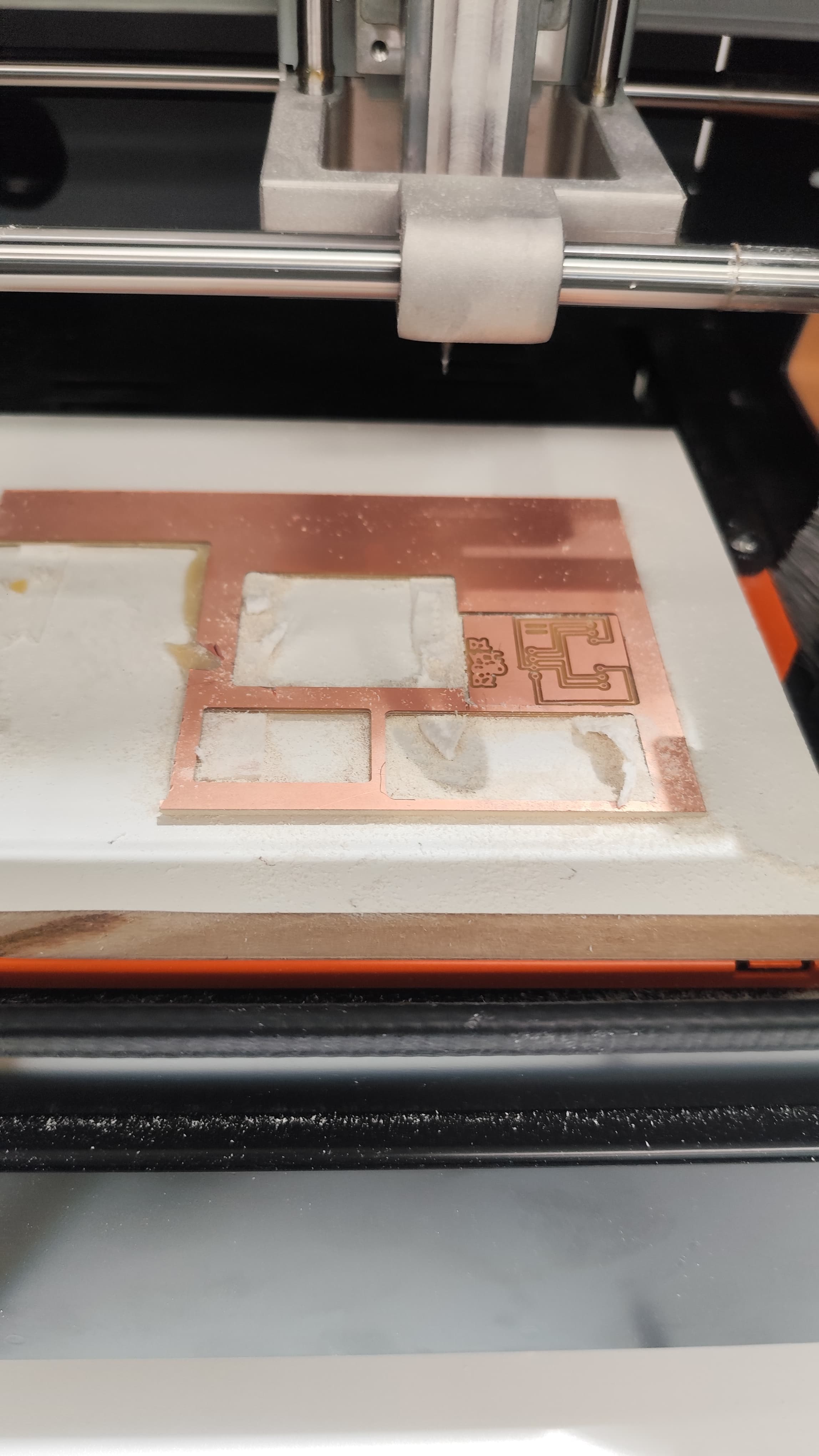
Step 4: PCB Manufacturing
The PCB manufacturing was performed using the Monofab SRM-20 milling machine, ensuring precision in
electrical connections and necessary drillings for electronic components.
Step 5: Soldering and Connections
With the PCB manufactured, necessary electronic components, including the ATTINY412 microcontroller
and specific servo motor connections, were soldered.
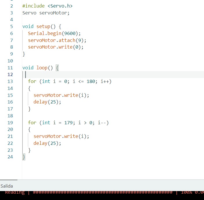
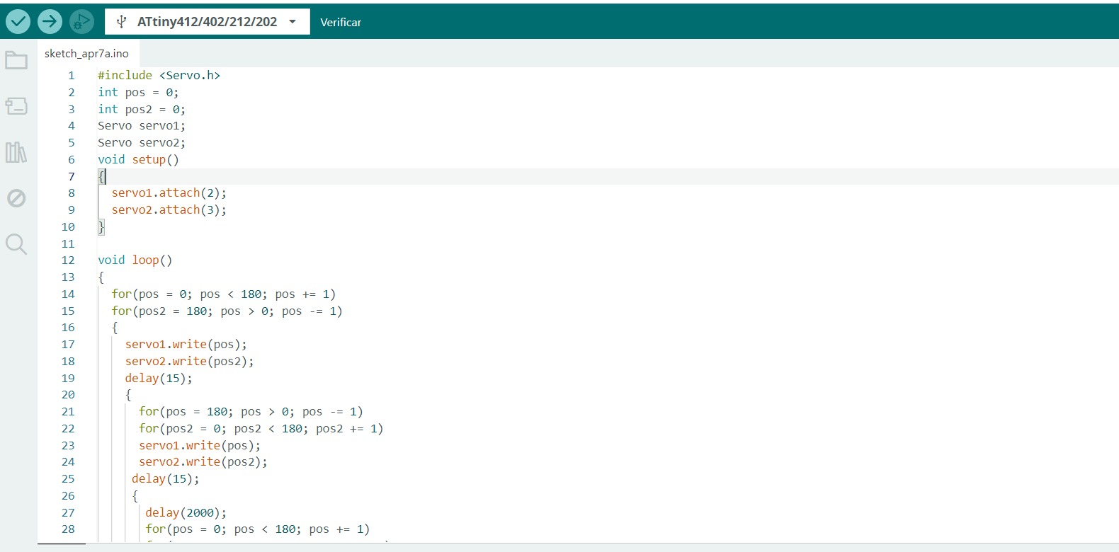
Step 6: Microcontroller Programming
Once the circuit was fully assembled, the code required to control both servo motors was developed.
The code was designed for coordinated and precise movement, showcasing the ATTINY412’s capability to
effectively manage external devices.
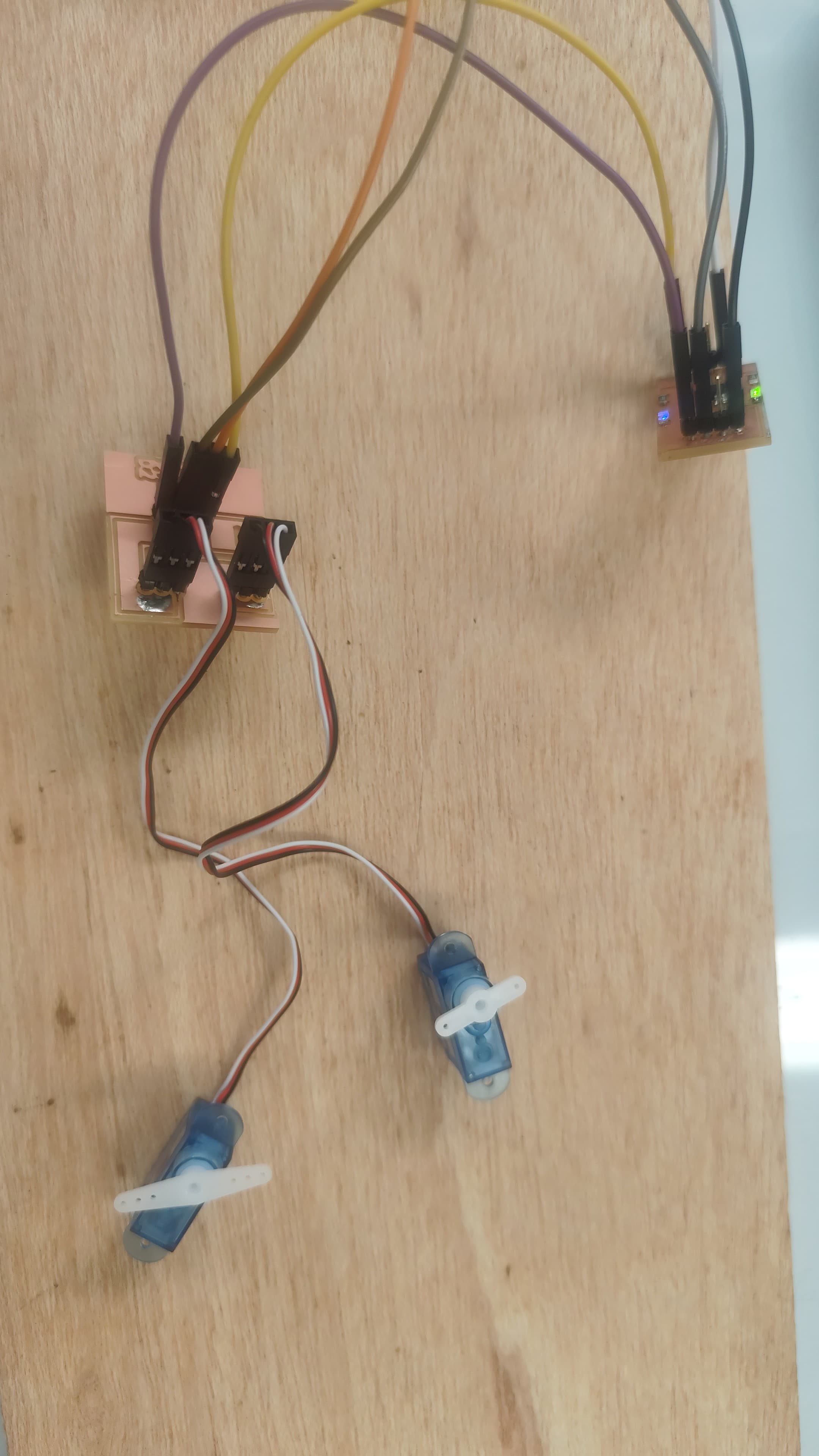
Step 7: Testing and Validation
Finally, the code was loaded onto the microcontroller, and the servo motors' functionality was
tested. The obtained results demonstrated correct operation, confirming the effectiveness of the
design and programming.
This project successfully demonstrated integrating output devices with custom electronic boards,
showcasing skills in electronic design, digital fabrication, programming, and functional validation.
This methodology can be replicated by following the detailed steps above, allowing students and
professionals to adapt the procedure according to their specific needs.
Week 10: Conclusion
This week's activities provided valuable insights into integrating and managing output devices
using custom-designed electronic boards. Through the combination of schematic design, PCB
fabrication, microcontroller programming, and rigorous testing, we reinforced essential skills
necessary for developing advanced electronic systems. The hands-on experience significantly
contributed to our understanding of electronic system design and validated our capability to
execute precise and functional solutions.
Resource Download
Click the button below to access and download all available materials.