Probe an input device(s)'s analog levels and digital signals
Document your work on the group work page and reflect on your individual page what
you learned
Individual Assignment
Measure something: add a sensor to a microcontroller board that you have designed
and read it.
Manuel Ayala-Chauvin Institution: Fablab - Universidad Tecnológica Indoamérica Year: 2025
Group assignment: Probe an input device’s analog levels and digital signals,
document the work, and write a personal reflection on the individual page.
Team: Manuel Ayala-Chauvin, Sandra Nuñez-Torres Institution: Fablab - Universidad Tecnológica Indoamérica Year: 2025
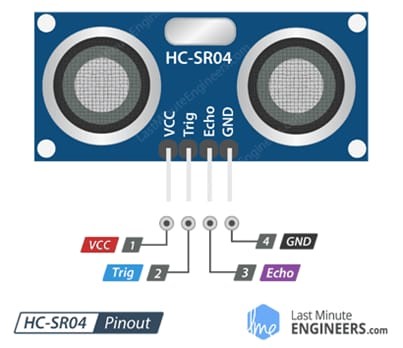
1. Connection Diagram of the HCSR04 Sensor
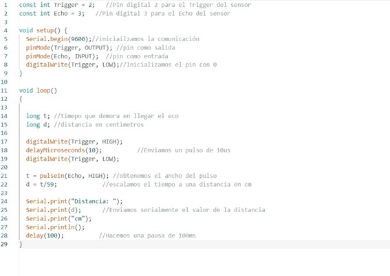
We used the HCSR04 ultrasonic sensor connected to an Arduino Uno board as follows:
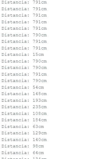
We placed different objects at various distances in front of the sensor and recorded the
measurements. The readings were consistent, with minimal error at short distances.
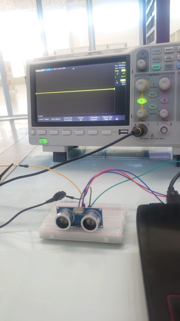
4. Oscilloscope Visualization
We connected the ECHO pin to the oscilloscope to observe the digital signals generated by the sensor.
This allowed us to analyze the pulses produced for each measurement.
5. Test Video
We recorded a short video showing the full setup and real-time signal output:
This assignment helped us understand how sensors convert physical phenomena into digital data and how
to visualize these signals using an oscilloscope. Team collaboration was key to sharing ideas,
troubleshooting, and completing the project effectively.
Individual Reflection (for personal page)
I gained a better understanding of how to capture and interpret digital signals and how sensor data
can be processed in physical computing projects. I also learned the importance of sensor response
time in accurate measurements.
Individual Assignment: Measure Something
Objective
The primary objective of this individual assignment is to implement a real-world measurement using a
sensor interfaced with a custom-designed microcontroller board. The specific task is to detect sound
using a digital sensor and to process this data for a visual and logged response. By doing so, the
project not only demonstrates the ability to capture a physical event but also showcases the
integration between hardware components and software logic. This setup can serve as a foundational
element for more complex systems that rely on environmental sensing and user interaction.
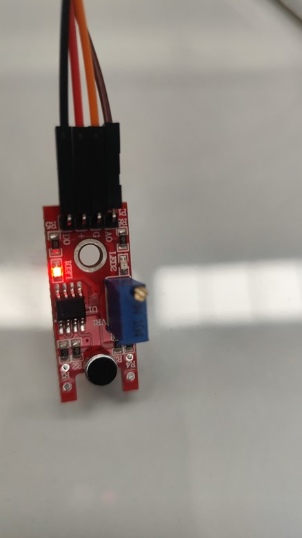
Sensor Used: KY-038
The sensor selected for this task is the KY-038, which is a sound detection module equipped with an
electret microphone. The KY-038 module is widely used in prototyping and educational electronics due
to its simplicity, affordability, and clear functionality. The module includes both analog and
digital outputs. The analog output provides a continuously variable voltage level based on sound
intensity, while the digital output emits a binary HIGH or LOW signal based on whether the detected
sound level exceeds a threshold. The threshold can be manually adjusted using the onboard
potentiometer, allowing for calibration based on ambient noise conditions or the desired sensitivity
level.
This modular sensor is well-suited for projects that involve detecting claps, knocks, or other
sudden noises in a room. Its plug-and-play design enables quick testing and integration with
Arduino-compatible microcontroller boards or custom-designed boards built around ATmega or other
microcontrollers.
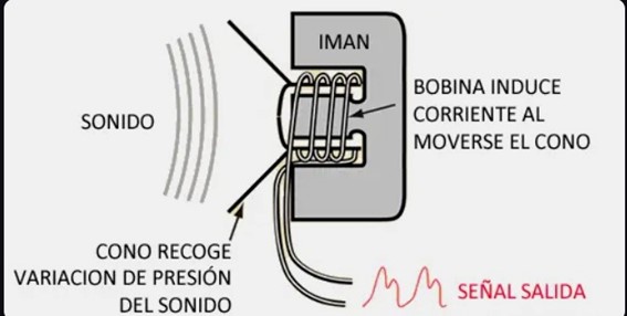
Working Principle
The KY-038 sound sensor operates on a straightforward principle. It consists of four main
components: an electret microphone, an operational amplifier, a comparator circuit, and an
adjustable potentiometer. The microphone captures ambient sound and converts it into a small analog
voltage. This signal is then amplified by the operational amplifier to make it more detectable by
the comparator.
The comparator takes the amplified signal and compares it to a reference voltage set by the
potentiometer. If the signal surpasses this reference threshold, the comparator outputs a HIGH
signal on the D0 pin, indicating that a significant sound event has occurred. This digital signal
can be used to activate devices such as LEDs, buzzers, or be logged by microcontrollers for further
processing.
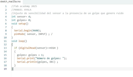
Code Implementation
The software component of this project is implemented using the Arduino programming environment. The
code is designed to initialize the digital pin connected to the KY-038 sensor as an input and the
onboard LED as an output. Within the main loop, the code reads the sensor state and determines
whether a sound has been detected. If the sensor's digital output is HIGH, indicating a loud sound
was detected, the LED is turned on and a message is sent to the serial monitor.
This process allows the user to receive both visual (via the LED) and textual (via serial
communication) feedback when a sound is detected. This kind of feedback is useful for debugging and
for verifying that the system is functioning correctly.
		  int sensorPin = 2; // KY-038 digital output connected to pin 2
		  int ledPin = 13;   // Onboard LED

		  void setup() {
			pinMode(sensorPin, INPUT);
			pinMode(ledPin, OUTPUT);
			Serial.begin(9600);
		  }

		  void loop() {
			int sensorState = digitalRead(sensorPin);
			if (sensorState == HIGH) {
			  digitalWrite(ledPin, HIGH);
			  Serial.println("Sound detected");
			} else {
			  digitalWrite(ledPin, LOW);
			}
			delay(100);
		  }
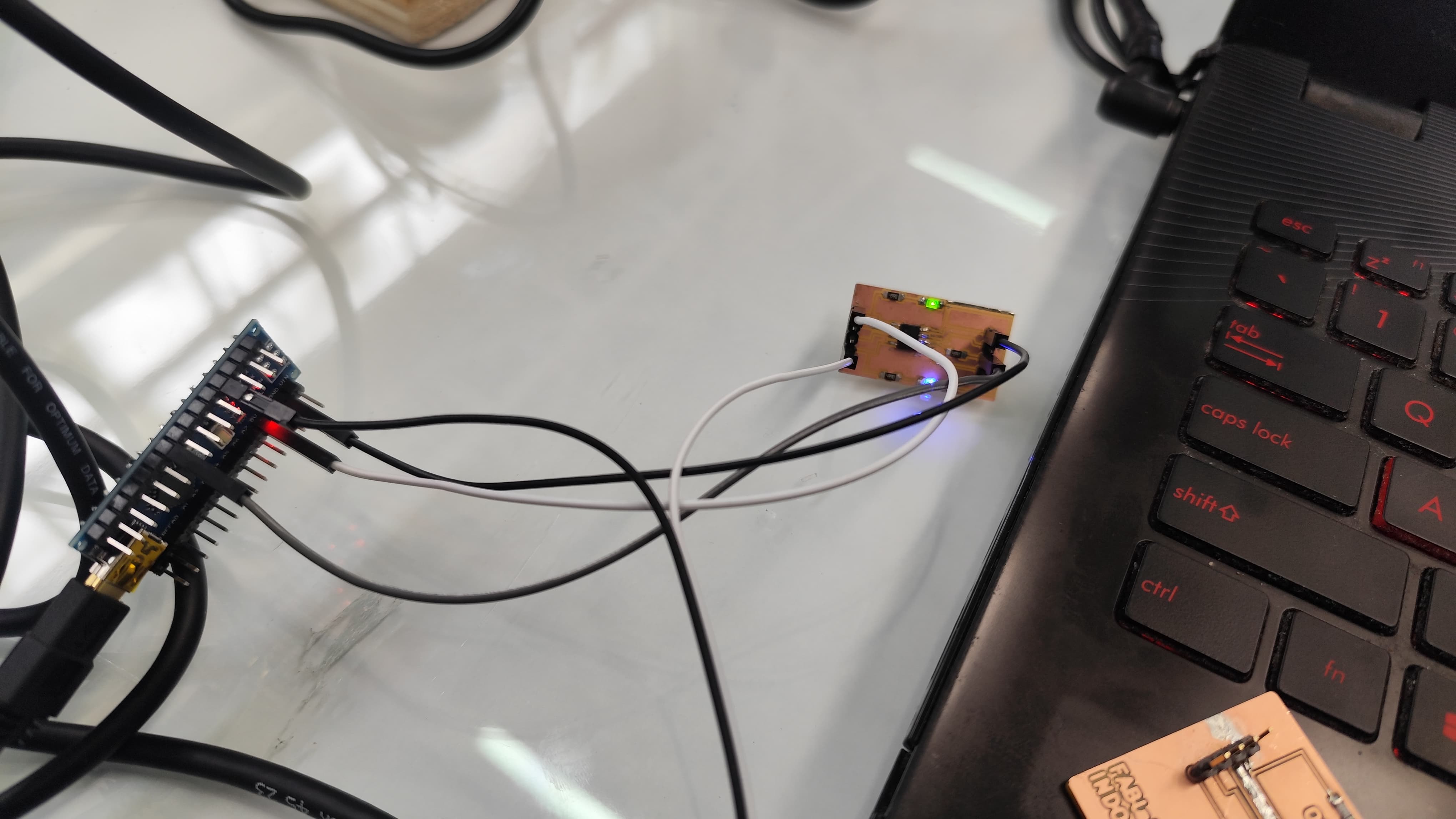
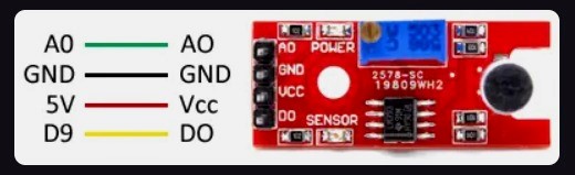
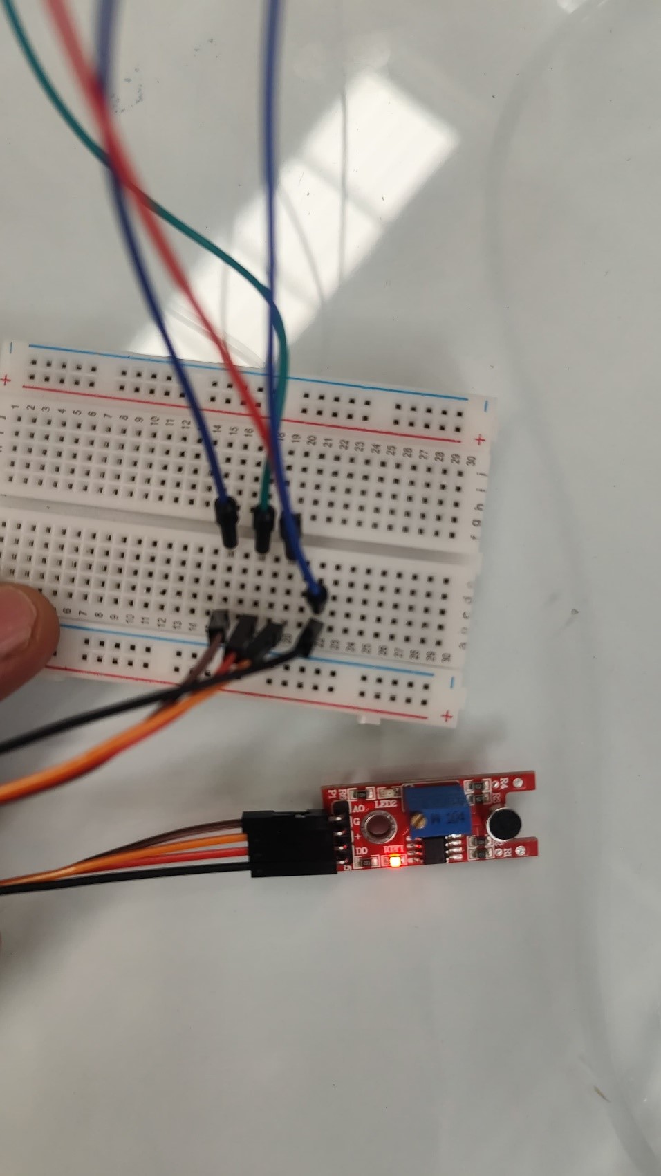
Wiring and Connections
To properly connect the KY-038 to the microcontroller board, ensure the following pin mapping is
used:
VCC should be connected to the 5V power output of the microcontroller board
GND must be connected to the ground (GND) pin
D0 should be connected to a digital input pin on the board (e.g., pin 2)
LED can be connected to digital pin 13 for visual indication
Always double-check your wiring to avoid incorrect connections which might damage the sensor or
yield incorrect readings. Use proper connectors or soldered joints if the circuit is not being
assembled on a breadboard.
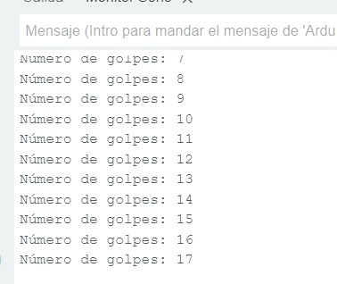
Data Reading and Observations
Once everything is set up and powered on, the KY-038 sensor actively listens for sound. When a loud
noise, such as a hand clap or a tap near the microphone, occurs, the sensor's D0 output goes HIGH.
This transition is immediately detected by the microcontroller, which responds by turning on the LED
and printing "Sound detected" to the serial monitor.
This real-time response makes the system useful for applications that require instantaneous sound
recognition. Moreover, by turning the potentiometer on the sensor, you can adjust how sensitive it
is to sound. This is particularly helpful in noisy environments where you want to filter out
background noise and focus only on specific, louder sound events.
Demonstration Video
A video demonstrating the working setup is available at the following link. This provides visual
confirmation of the behavior described above and helps users understand the sensor’s responsiveness
in real-time applications.
This project serves as an introductory exercise in the integration of sensors with custom
microcontroller platforms. It effectively demonstrates how to detect physical phenomena—specifically
sound—using electronic components. The KY-038 sound sensor proves to be a highly useful tool for
such applications due to its simplicity, adjustability, and ease of integration.
Through this assignment, we explored key engineering practices such as sensor interfacing, threshold
tuning, real-time feedback via LEDs, and debugging using serial communication. These skills are
foundational for more advanced embedded systems projects where environmental monitoring or event
detection is required. Additionally, this setup can be expanded to interact with other systems such
as alarms, data loggers, or wireless transmitters, making it a flexible base for future innovations.
Week 9: Conclusion
During this week, exploring input devices allowed us to understand how sensors can capture
physical phenomena from the environment and translate them into useful digital data for embedded
systems. Through group work with the HC-SR04 ultrasonic sensor and the individual development
with the KY-038 sound sensor, we gained hands-on experience in both sensor connections and
programming for data capture and visualization.
Using the oscilloscope was essential for observing digital signals in real time, which provided
a deeper understanding of sensor behavior and response time. We also adjusted sensitivity
levels, verified activation thresholds, and learned how to interpret signals in both the
physical and logical domains.
This experience reinforced the importance of proper integration between hardware and software,
as well as clear documentation to support future improvements or system expansions. In summary,
this week marked a key step toward developing intelligent interactive systems that respond to
real-world stimuli.
Resource Download
Click the button below to access and download all available materials.