2. Design and Fabrication of a Non-Subtractive Object
The objective was to design and manufacture a 3D object that would be impossible to create using
subtractive methods such as CNC milling, turning, or laser cutting.
To achieve this, a complex structure was designed in SolidWorks incorporating
internal cavities, intricate interlocking geometries, and enclosed voids that only additive
manufacturing can realize.
2.1. Parametric Design Approach
A parametric modeling strategy was adopted, where key dimensions such as wall
thickness, bridge length, internal clearance, and overhang angles were defined as variables.
This allowed for dynamic adjustments and fine-tuning of the model to optimize it for 3D printing
constraints.
Parametric design not only accelerates prototyping but also enables customization and iterative
refinement without redrawing the model from scratch.
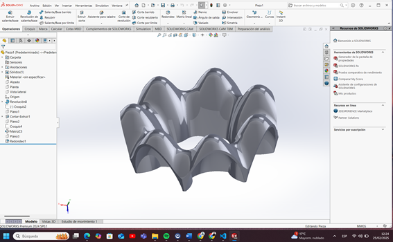
This figure shows the digital 3D model designed using parametric tools in SolidWorks.
The structure includes suspended bridges, internal channels, and closed volumes that highlight the
unique capabilities of additive manufacturing.
Adjustable features such as bridge length and cavity dimensions can be easily modified thanks to the
parametric nature of the design.
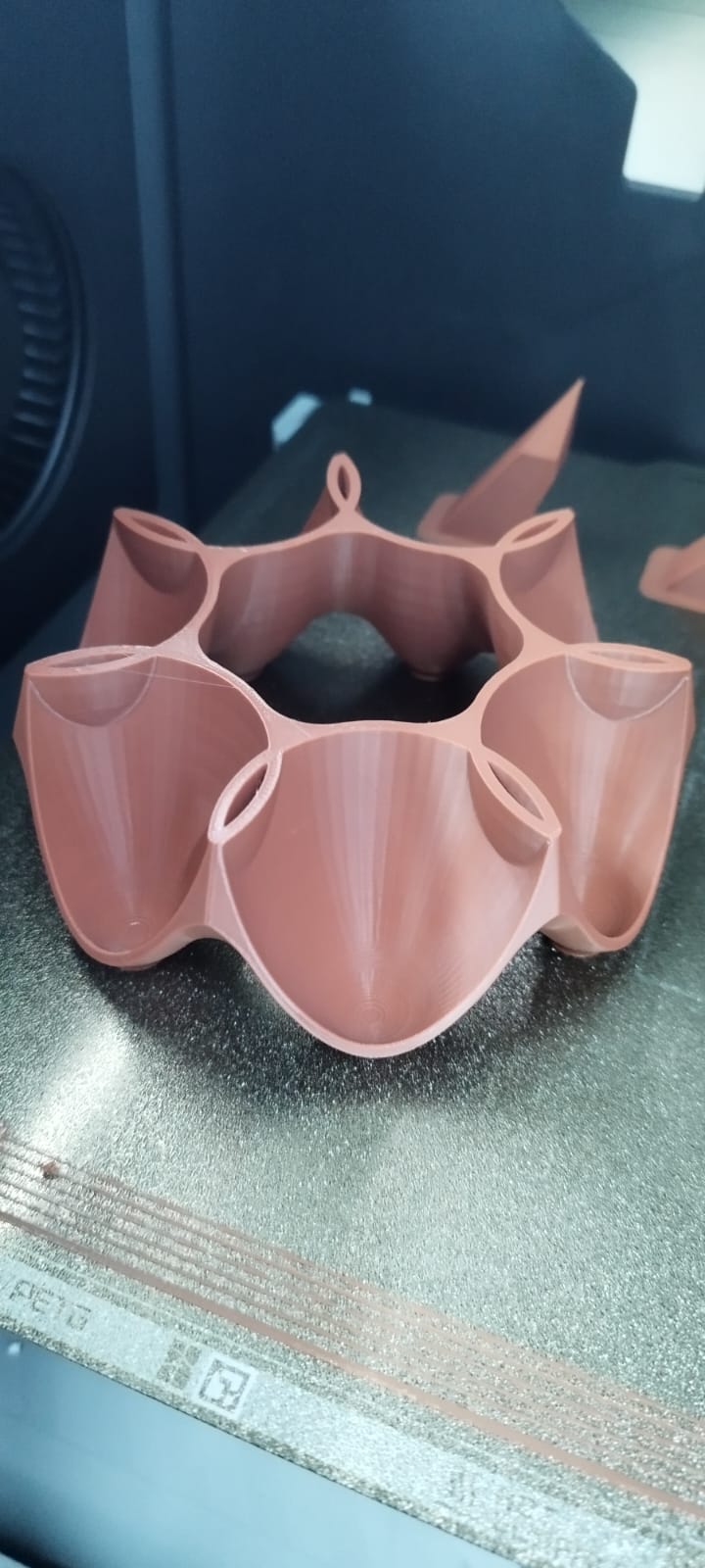
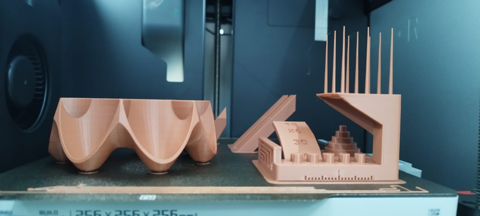
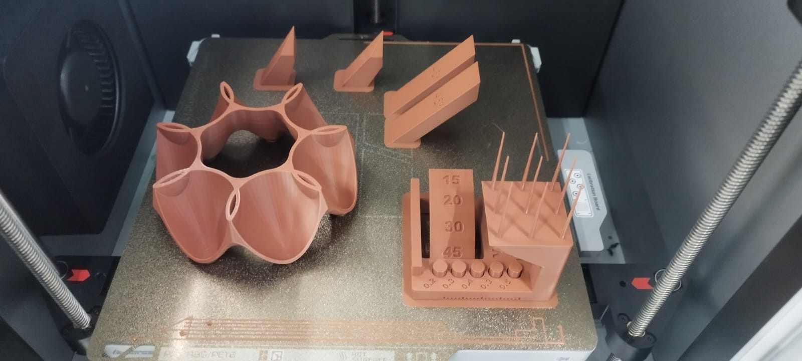
This figure presents the final physical object after 3D printing.
Critical details like unsupported bridges, enclosed cavities, and overhanging features were
successfully fabricated without post-processing or internal support removal,
demonstrating a successful application of Design for Additive Manufacturing (DfAM) principles.
2.2. Challenges Encountered
During the design and fabrication process, several challenges were identified:
- Internal Supports: Enclosed cavities required careful design to avoid the need
for internal supports that could not be removed post-printing.
- Overhang and Bridging Management: Some sections with bridges exceeding 10 mm
showed slight sagging, requiring design adjustments or printing orientation changes.
- Dimensional Accuracy: Fine clearances in interlocking parts had to account for
the typical 0.2–0.4 mm tolerance variation inherent to FDM processes.
- Print Orientation: Strategic orientation was necessary to balance surface
finish quality, minimize support material usage, and ensure mechanical strength in critical
areas.
2.3. Lessons Learned
This assignment provided a deeper understanding of how to apply Design for Additive
Manufacturing (DfAM) principles, leverage parametric modeling to
optimize designs,
and anticipate real-world fabrication constraints during the digital design phase.
It also reinforced the importance of prototyping iterations when dealing with tight tolerances or
complex geometries.
3. 3D Scanning of an Object
3.1. Scanning Methods
Two methods were applied to capture the three-dimensional geometry of a physical object:
Mobile Phone Scanning
- App used: KIRI Engine
- Procedure:
- Multiple photos were taken from various angles around the object.
- Images were processed via photogrammetry to reconstruct a 3D model.
- An STL file was generated for visualization and printing purposes.
Dedicated 3D Scanner (Optional)
Using a dedicated 3D scanner (if available) significantly improves resolution and detail, especially
for complex textures or intricate surfaces.
Practical Recommendations: Ensure diffuse lighting, avoid reflective or translucent
materials, and maintain consistent coverage of the object.
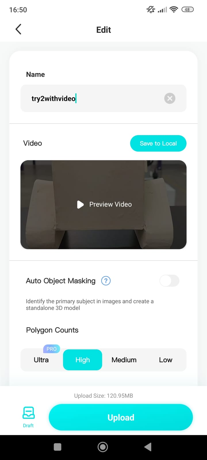
Figure 1 - Mobile 3D Scanning
Process:
The image illustrates the scanning setup using a mobile phone.
A series of photographs were systematically captured from multiple angles around the object to
ensure complete surface coverage,
an essential step for successful photogrammetry reconstruction.
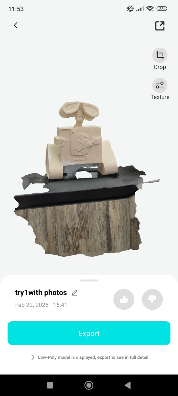
Figure 2 - Reconstructed 3D Model:
This figure shows the resulting 3D model generated after processing the captured images.
The mesh was exported in STL format, highlighting the object's main features and geometry suitable
for further use in digital applications or 3D printing.
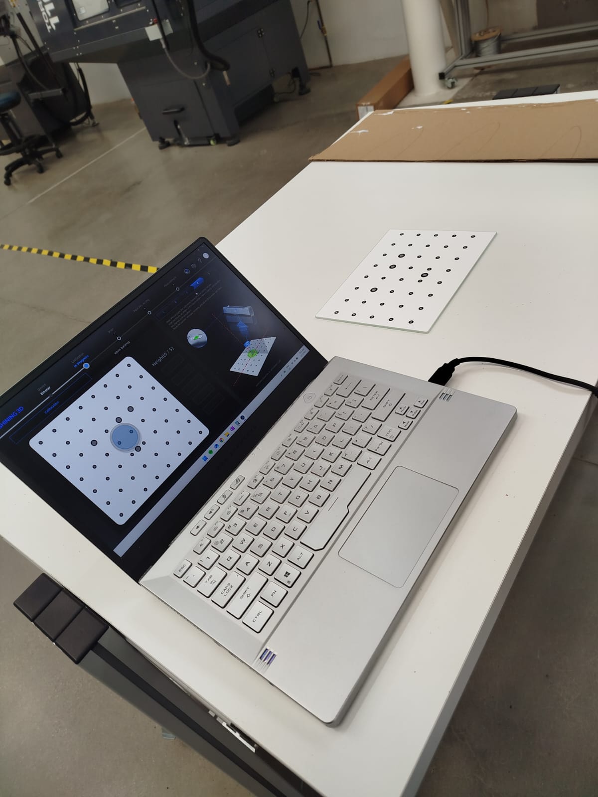
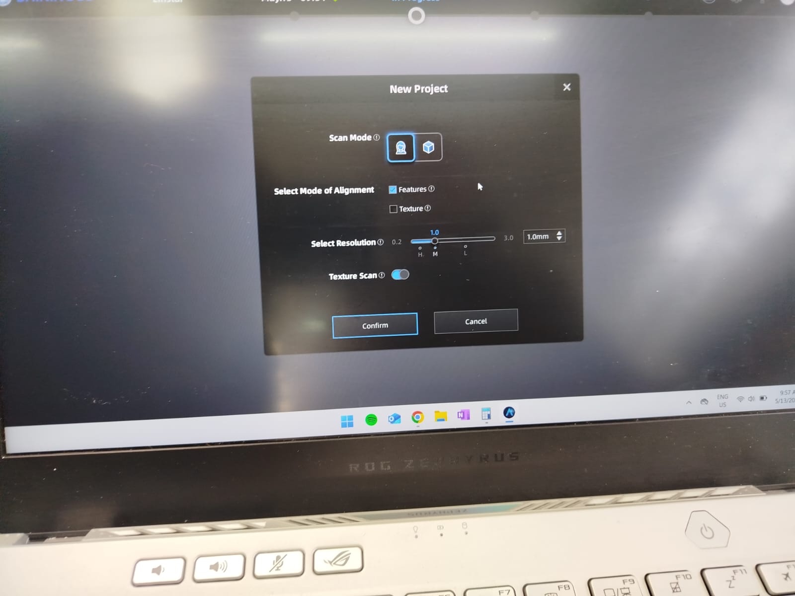
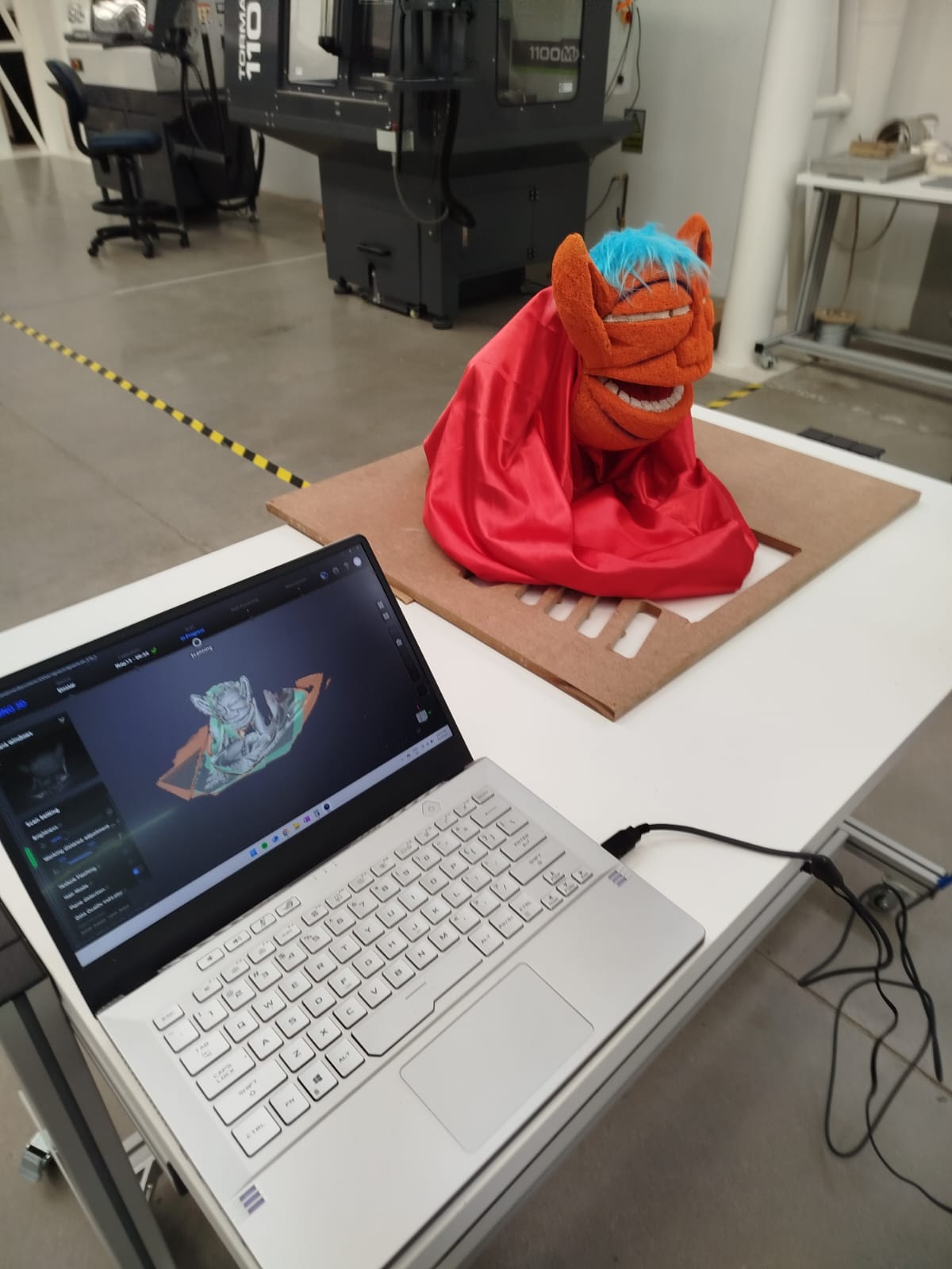
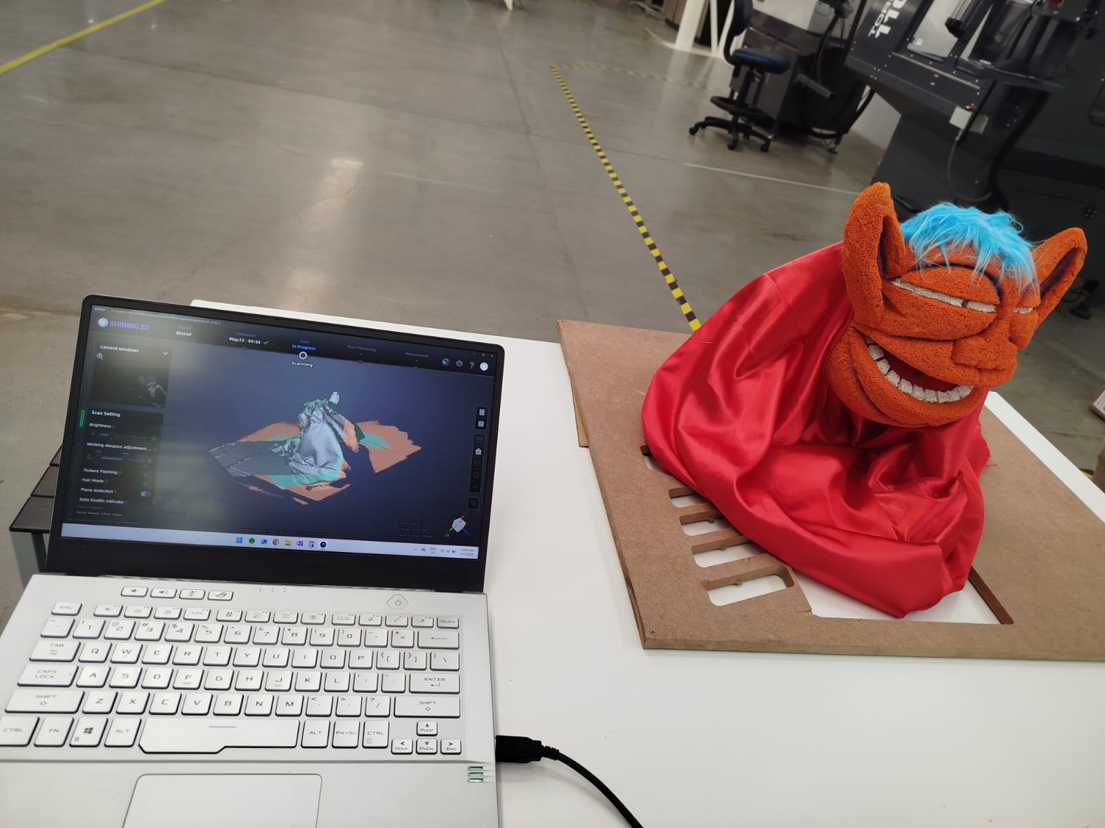
4. Scanning using the Shining 3D
To begin the scanning process, a perforated calibration board was placed on a flat surface. The
scanner was set to feature alignment mode, with a resolution of 1.0 mm and texture scan enabled
using the Shining 3D software.
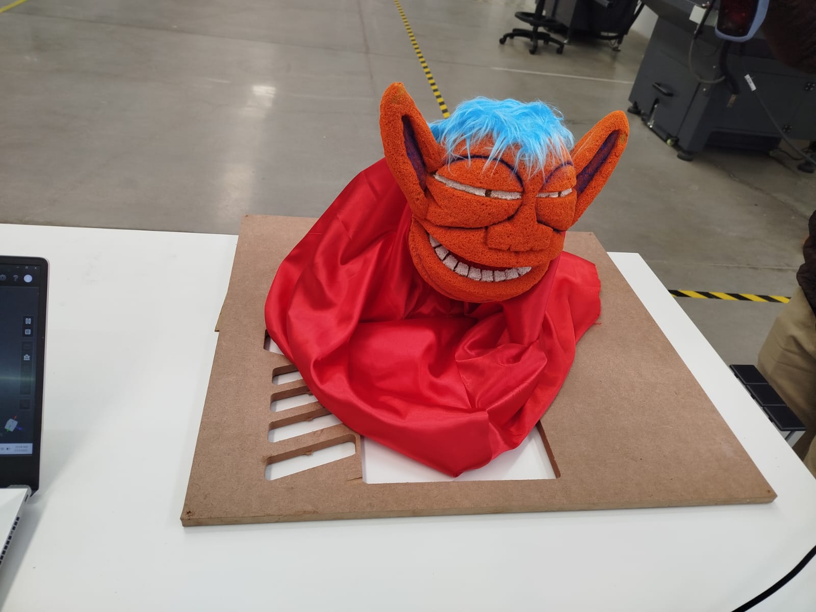
4.1. Object Scanning
The object to be scanned was a puppet with detailed facial features and texture. Several passes were
made with the scanner to capture the full geometry.
4.2. Mesh Cleanup and STL Export
The mesh was postprocessed in the scanning software to close holes and remove noise. The result was
exported in STL format, ready for 3D printing.
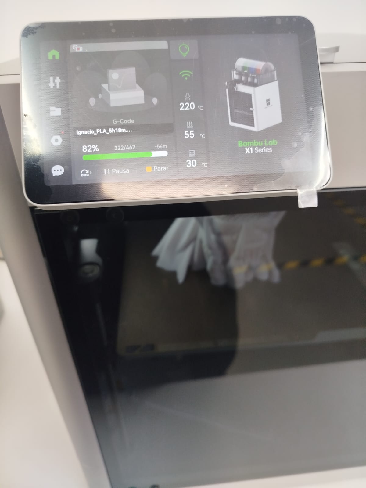
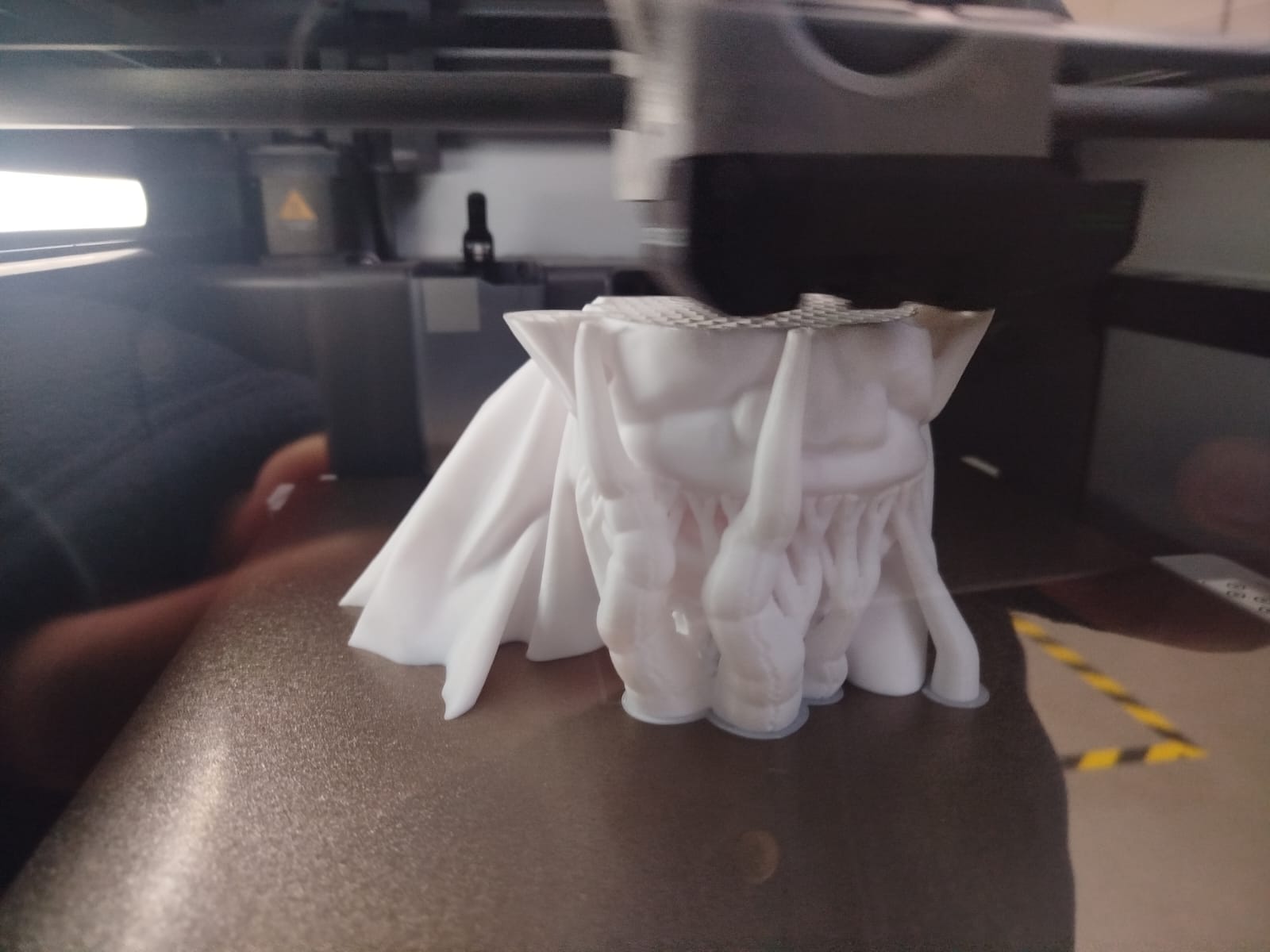
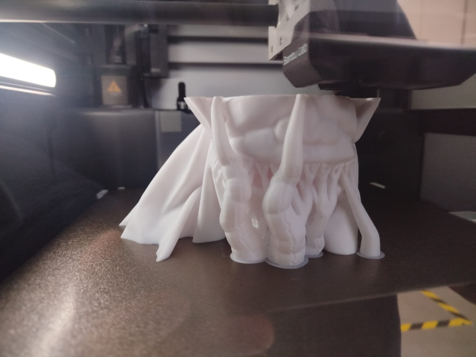
4.3. 3D Printing the Model
Printing was done using a Bambu Lab X1 Series printer with white and blue PLA. The model required
support structures due to the overhanging features.
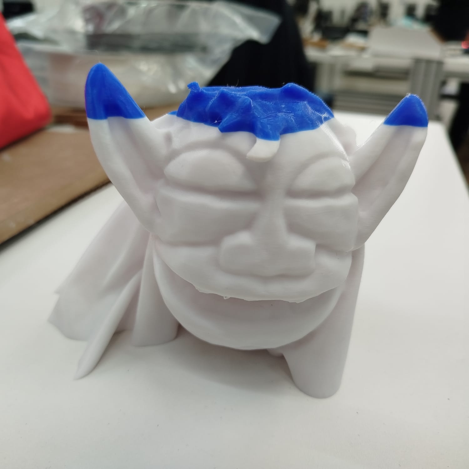
4.4. Conclusion
This process allowed for accurate digitization and physical reproduction of a complex object. The
final result is a durable, tangible version of the puppet, with potential uses in animation,
education, and product prototyping.