Ensure the material is laser-compatible and does not release toxic fumes.
Check that the laser optics (mirrors and lenses) are clean.
Set power, speed, and frequency according to the material specifications.
Close the machine’s lid properly before starting the cut.
1.2.2 During Operation
Never leave the machine unattended while running.
Watch the process through the safety window without opening the lid.
In case of fire, stop the machine immediately and use the lab fire extinguisher.
1.2.3 After Operation
Wait for the cut pieces to cool before handling.
Clean any debris from the cutting area.
Turn off the machine and disconnect it if not in use for an extended period.
2. Vinyl Cutter (Roland) Safety Rules
2.1 Before Operation
Ensure the blade is properly adjusted and in good condition.
Set the correct pressure and speed based on the material.
Align and secure the vinyl properly in the machine.
2.2 During Operation
Keep hands away from the cutting head while the machine is running.
Supervise the process to prevent material misalignment or blade damage.
Stop the machine immediately if an issue occurs.
2.3 After Operation
Carefully remove the cut material and clean the workspace.
Turn off the machine when not in use.
Store blades and tools properly after use.
2.4 Emergency Procedures
In case of fire, use the CO₂ extinguisher available in the FabLab.
Report any incidents or machine malfunctions to the FabLab supervisor.
Follow first aid protocols and contact lab personnel if an injury occurs.
3. Characterization of the Epilog FusionMaker Laser Cutter
FabLab Indoamérica
3.1 General Information
Brand & Model: Epilog FusionMaker
Type: CO₂ Laser Cutter
Functionality: Precision cutting and engraving
Common Uses: Prototyping, fabrication, artistic engraving, industrial
applications
3.2 Technical Specifications
Laser Type: CO₂ laser
Power: 30W, 40W, or 50W options
Work Area: Approx. 24” x 12” (609 mm x 305 mm)
Resolution: Up to 1200 DPI
Speed & Power Control: Adjustable settings
3.3 Supported Materials
3.3.1 Cutting Capabilities
Wood (MDF, plywood, etc.)
Acrylic
Leather
Cardboard
Fabric
Some plastics (Non-PVC)
3.3.2 Engraving Capabilities
Glass
Ceramic
Coated metals
Prohibited Materials: PVC, polycarbonate, and materials that release toxic
fumes.
3.4 Key Features
Enclosure: Fully enclosed system with a transparent lid
Ventilation System: Integrated air exhaust
Control Panel: Digital interface
Air Assist: Reduces flaming and improves precision
Red Dot Pointer: Previews the cutting area
3.5 Laser Calibration Grid
Displayed in the first image, the power vs. speed test grid is used to determine optimal settings
for different materials.
Power settings range from 10% to 100%
Speed settings range from 10% to 100%
The darker the engraving, the more material was removed
3.6 Safety Considerations
Protective Gear: Safety glasses for reflective materials
Machine Supervision: Never leave unattended
Fire Prevention:
Keep a CO₂ fire extinguisher nearby
Avoid highly flammable materials
Ensure proper ventilation
Cleanliness: Regular maintenance to prevent overheating
4. Laser Cutter Tolerance Test
FabLab Indoamérica
4.1 Objective
This experiment aims to determine the optimal fit for interlocking laser-cut pieces by testing
different slot widths and evaluating tolerances.
4.2 Methodology
Material: Medium-density fiberboard (MDF) or plywood.
Laser Cutter Used: Epilog FusionMaker.
Slot Widths Tested: Ranging from 2.9 cm to 3.6 cm in 0.1 cm increments.
Kerf Consideration: Adjustments were made to account for material removal
by the laser.
Laser Settings: Power, speed, and frequency optimized for minimal burning
and clean cuts.
4.3 Observations
Tighter Fits: Slots between 2.9 cm - 3.2 cm required force for assembly.
Looser Fits: Slots between 3.4 cm - 3.6 cm allowed for easy but potentially
unstable connections.
Optimal Fit: Likely within the 3.2 cm - 3.3 cm range.
Burn Marks: Indicating laser power may be slightly high or multiple passes
were used.
4.4 Adjustments for Future Tests
Refining kerf compensation based on precise measurements.
Optimizing laser power and speed to reduce burns.
Testing different materials like acrylic and plywood for comparison.
Evaluating mechanical strength of each fit under load conditions.
4.5 Conclusion
This test is essential for achieving precise fits in interlocking structures such as furniture,
enclosures, and mechanical joints. Adjusting design files based on these results ensures
accurate assembly and functional strength.
Individual Assignment
1. Vinyl Cutting Process
This section details the step-by-step process to cut and apply heat-transfer vinyl onto fabric using
digital fabrication techniques. The process integrates design, machine setup, material handling, and
transfer techniques using a heat press.
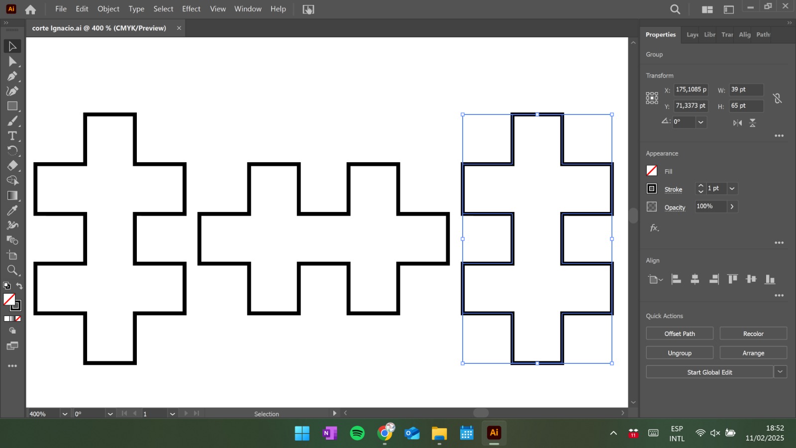
1.1. Design and Modeling in Illustrator
The design was created using vector shapes in Adobe Illustrator. The process involved:
Using the rectangle tool to create modular components.
Combining them using the Pathfinder tool to form a cross-based motif.
Applying symmetry and alignment tools for consistent spacing.
1.2. File Export
The design was exported in a format compatible with the vinyl cutter:
Save in JAPAN ILLUSTRATOR 3 format, compatible with the cutter.
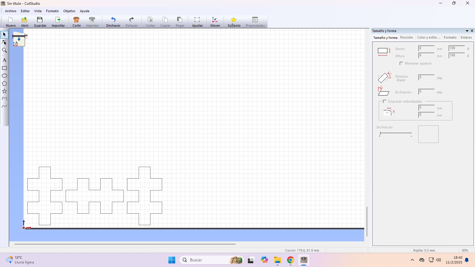
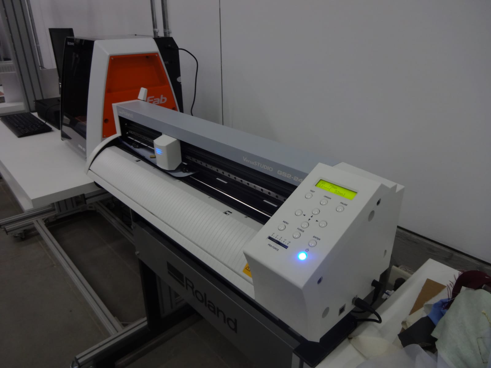
1.3. File Import into Vinyl Cutting Software
The exported design file was imported into the vinyl cutting software provided by Roland. It’s
important to:
Mirror the image if working with heat-transfer vinyl.
Verify alignment and scale before sending to the cutter.
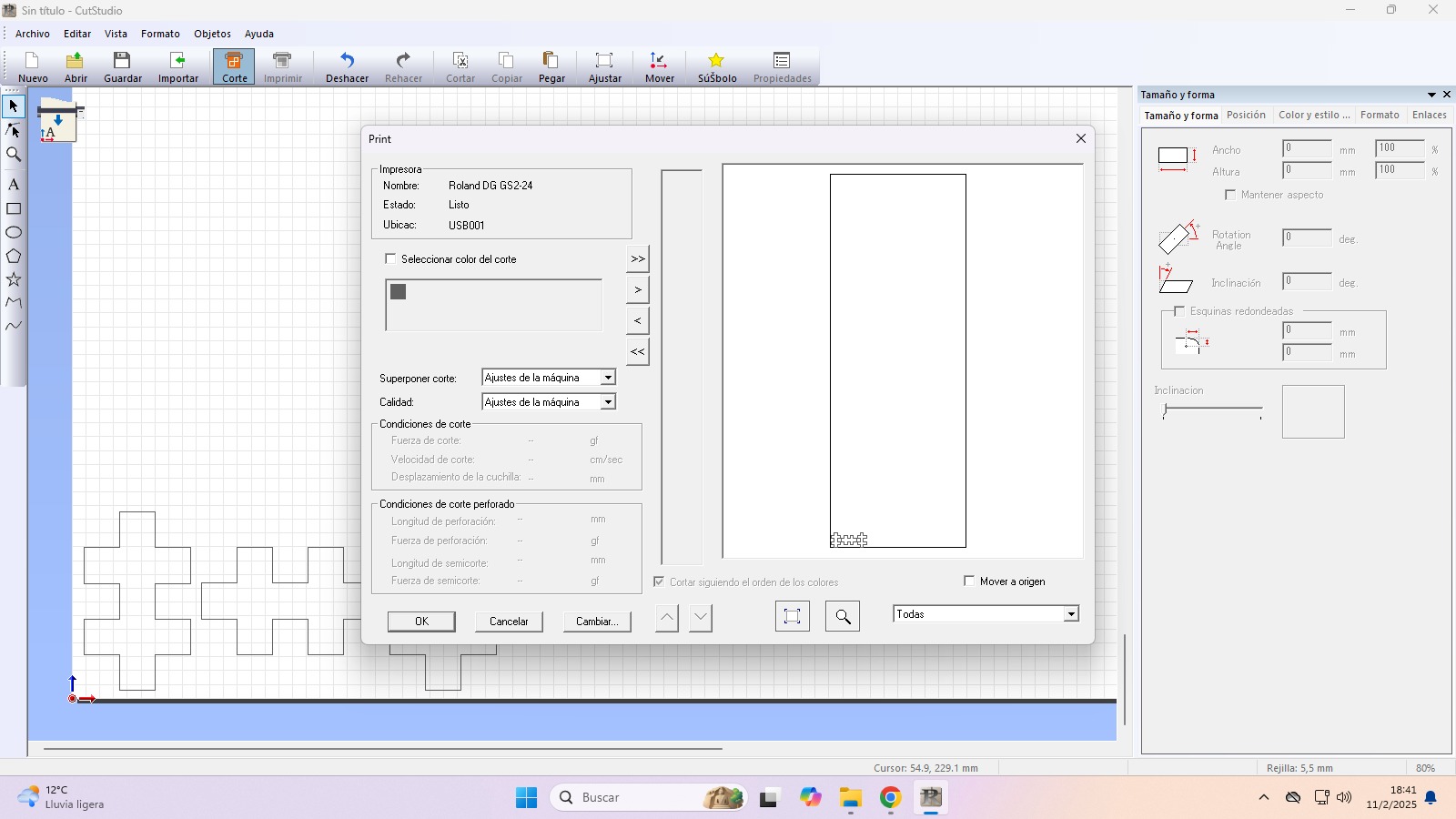
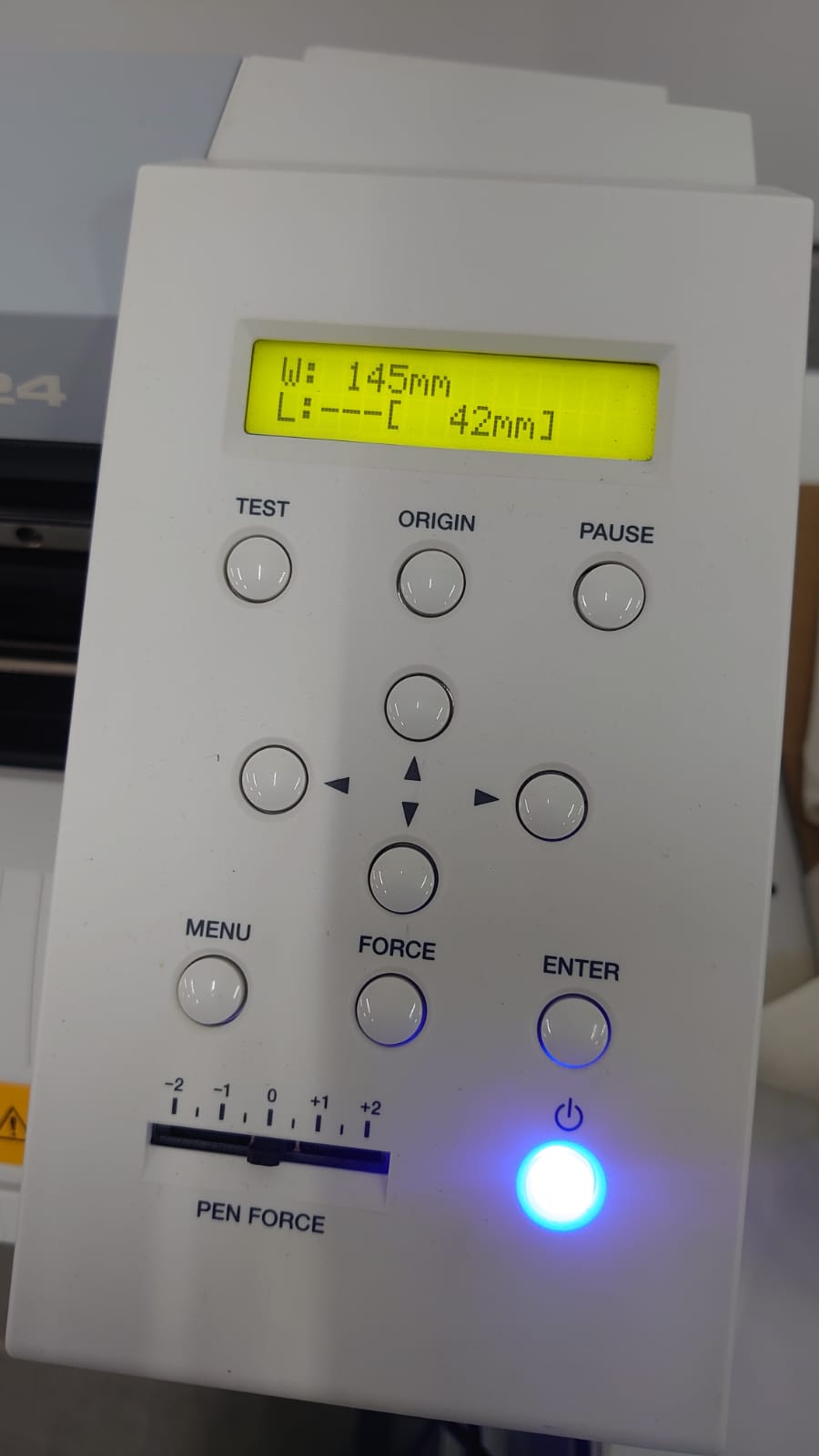
1.4. Machine Configuration
The vinyl cutter was configured with the following settings:
Blade force: 110 gf
Cutting speed: 10 cm/s
Blade type: 45-degree standard
1.5. Sending and Cutting
Send the design to the machine and ensure the vinyl is correctly placed.
Supervise the process for precise cuts.
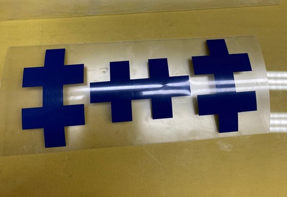
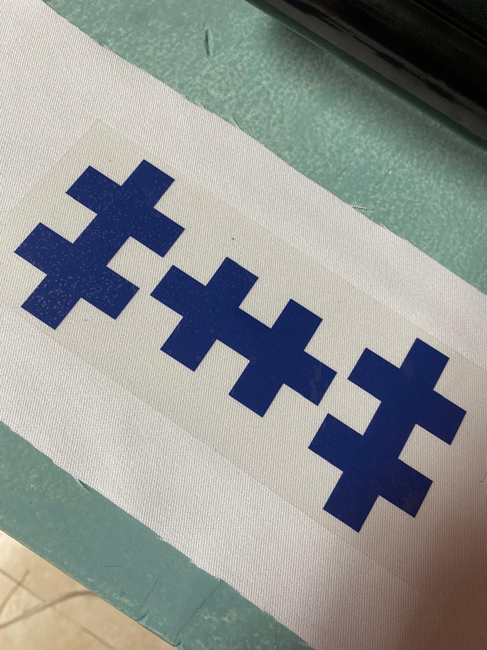
1.6. Weeding and Heat Application
After cutting, the excess vinyl was removed manually ("weeding") to reveal the final design. The
vinyl was then placed onto a white polyester fabric using the transparent carrier to position the
design.
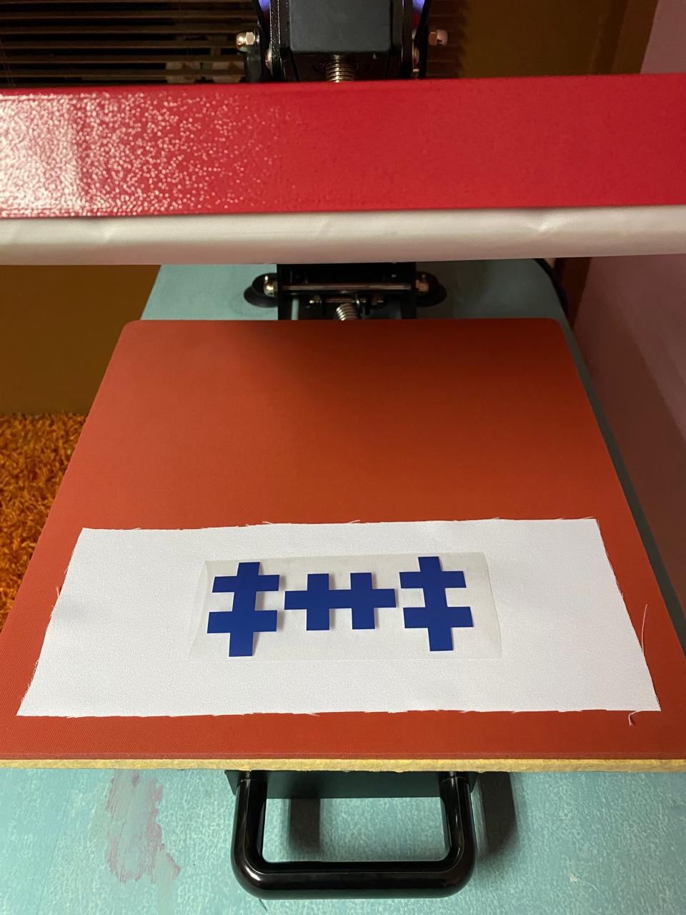
1.7. Heat Press Transfer
A heat press was used to transfer the vinyl onto the fabric. The settings used were:
Temperature: 160°C
Time: 15 seconds
Medium pressure
After pressing, the carrier sheet was left to cool slightly before removal.
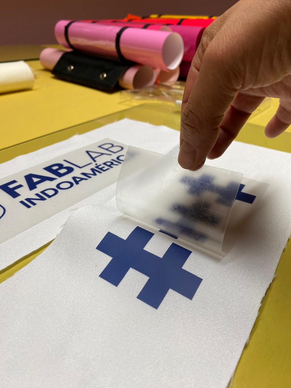
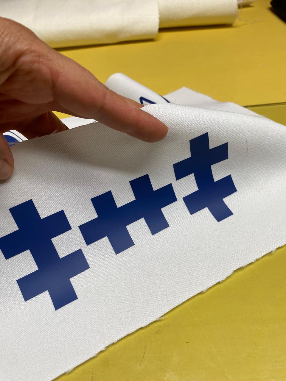
1.8. Removal and Application
The transparent carrier sheet was peeled off slowly, revealing a clean and durable finish on the
fabric. The result was precise, with sharp edges and strong adhesion.
Summary
This process can be applied to T-shirts, bags, and banners.
Proper mirroring and cutting depth are critical for success.
Pressing temperature and time must be adjusted according to the fabric and vinyl type.
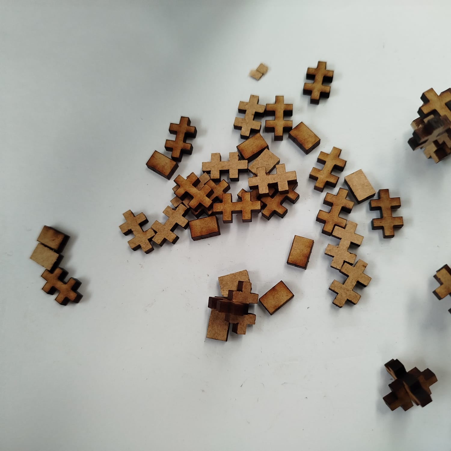
2. kit Standard Modular Pieces for Configurable Structures
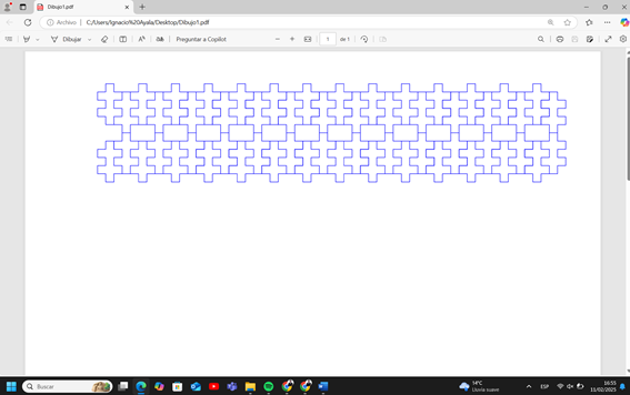
The image shows a set of laser-cut interlocking wooden pieces designed in a standardized modular
format.
These pieces can be assembled in various ways to create different 3D structures.
2.1. Modular Design Concept
The pieces follow a uniform interlocking system, meaning each component has standardized slot
widths
and depths.
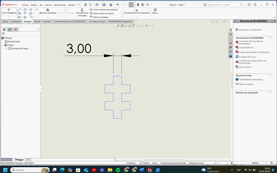
They resemble cross-shaped connectors, allowing them to fit together in multiple orientations.
The uniformity in dimensions enables scalability and expansion without the need for additional
connectors.
2.2. Features of the Pieces
Laser-Cut Precision: Ensures tight-fitting joints by compensating for kerf
width.
Symmetry: Allows multiple assembly possibilities without predefined
constraints.
Material: Likely MDF or plywood, chosen for its strength and ease of laser
cutting.
Edge Burn Marks: Indicate controlled cutting power for maintaining structural
integrity.
2.3. Configurability and Possible Forms
These pieces can be used to construct:
Geometric Shapes: Cubes, spheres, or irregular polyhedrons.
Mechanical Structures: Frames for lightweight mechanical systems.
Architectural Prototypes: Scaled-down modular buildings or conceptual
frameworks.
Artistic & Educational Models: Useful for hands-on learning and creative design
exercises.
2.4. Advantages of This System
Reusability – Components can be disassembled and reassembled into new
configurations.
Expandability – The modular nature allows for additional pieces to be
integrated easily.
Parametric Design – This system can be adapted for larger-scale projects
by
adjusting the slot dimensions.
Efficient Manufacturing – Minimal material waste and easy mass production
using a laser cutter.
2.5 Design and Laser Cutting Process
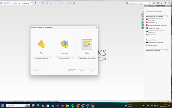
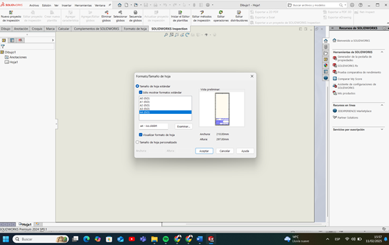
Open SolidWorks: Select "File" → "New Part" → "2D Drawing".
Select Size: Configure the appropriate drawing size.
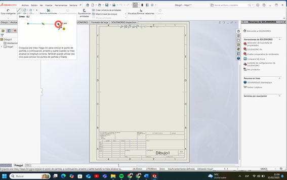
Create Sketch: Select the "Line" tool to start the sketch.
Draw the Piece: Create the 2D design with precise measurements.
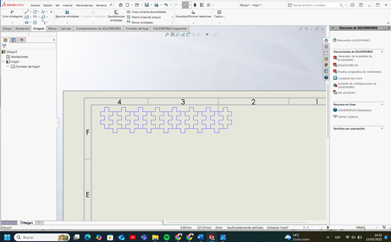
Create Cutting Mesh: Prepare the design for the laser cutting process.
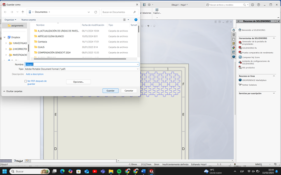
Export to PDF: Generate a PDF file of the final design.
Send to Machine Software: Upload the PDF file to the cutting machine
software.
Laser Cutting Parameters Used
This section documents the calibrated laser cutting settings used for 3 mm MDF on the Epilog
FusionMaker laser cutter. The goal was to achieve clean cuts with minimal burn marks and
accurate fit.
Material: MDF (Medium Density Fiberboard)
Thickness: 3 mm
Laser Cutter: Epilog FusionMaker (30W)
Cutting Type: Vector cut
Speed: 20%
Power: 100%
Frequency: 500 Hz
Number of Passes: 1
Focus Mode: Auto-focus enabled
Air Assist: Enabled
Ventilation: Extraction system ON
Kerf Compensation
The kerf (material lost to the laser beam) was measured at approximately 0.12
mm. This value was considered in the slot design to ensure tight but functional
interlocking.
Calibration Process
A power-speed test grid was performed on MDF with squares cut at various speed and power
values.
At 15% speed and 100% power: full cut with slight burn.
At 25% speed and 90% power: incomplete cuts in denser grain areas.
Final setting selected: 20% speed, 100% power, 500 Hz — produced clean,
complete cuts.
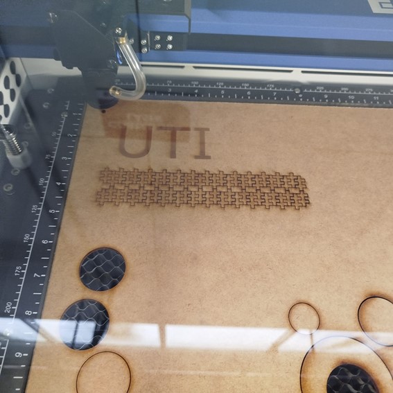
Cutting process in progress for the modular parametric kit on the Epilog laser
cutter.
These settings were calibrated through preliminary testing to minimize burning and ensure proper
part separation without excess kerf loss. The results showed clean edges and consistent fit
among components.
Execute the Cut: Start the laser cutting process on the chosen material.
Kit: Assembled parts kit.
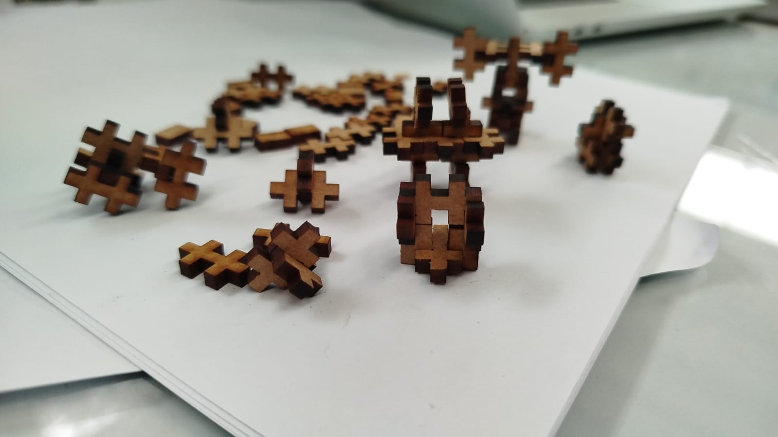
2.6 Exploring Creative and Usable Forms with the Parametric Construction Kit
After cutting and assembling my parametric construction pieces, I explored their combinatorial
potential through iterative physical prototyping. The results demonstrate that this kit can be used
not only as an abstract modeling exercise but also to develop functional, playful, and modular
structures.
Modular Assembly and Design Flexibility
Assembling small components into complex, recognizable shapes such as animals, abstract
characters, and symmetrical forms.
The cross-shaped modules allow multi-directional connections, which unlocks vertical stacking and
horizontal bridging. This makes the kit highly adaptable for toy design, interactive puzzles, or
educational STEM tools.
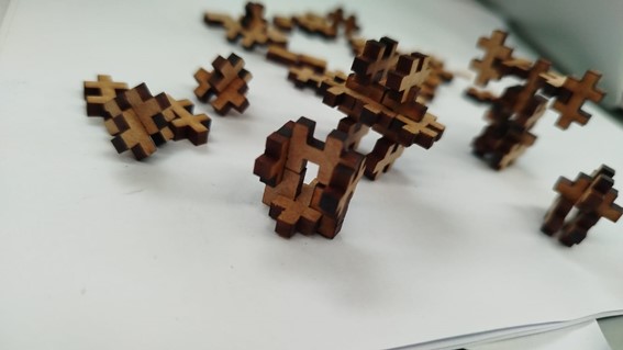
Forming Usable Objects
Top view showing the variety of pieces and how they can recombine into larger structures
with minimal components.
From a few repeated elements, I was able to create:
A freestanding character with legs and antennas (potential mascot or figurine)
Interlocking rings and abstract animals
Reconfigurable connectors that could serve as structural joints for small-scale mockups or
design prototypes
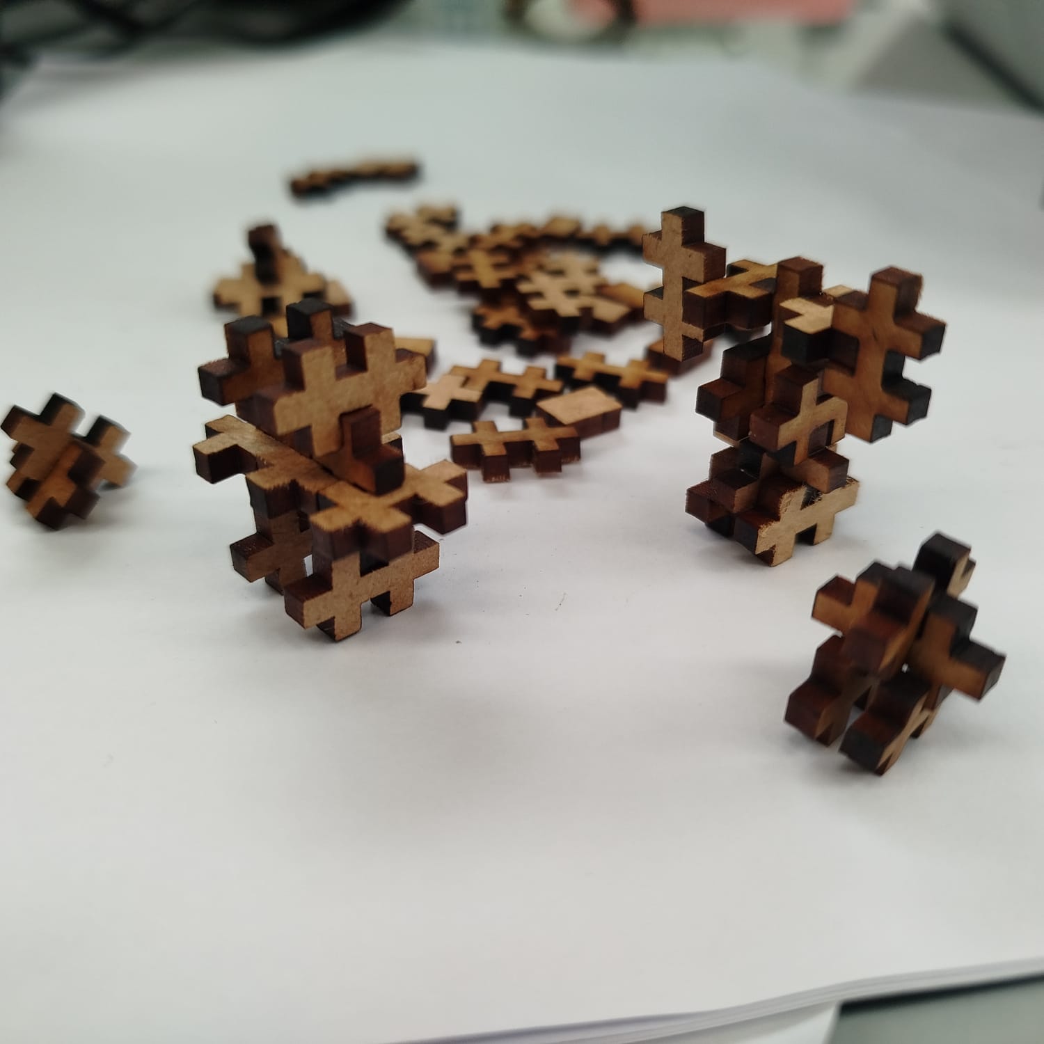
Stability and Interaction
The joints hold well enough to support vertical loads and stand freely, opening the
possibility for mechanical experiments or decorative models.
The burnt wooden edges from laser cutting also improve grip and friction between parts, avoiding
slippage without glue or fasteners. This adds usability for design testing or classroom
demonstrations.
Conclusion and Possibilities
Overview of a small ecosystem of forms created from the same kit: playful, structured,
modular.
This parametric construction kit is not just a conceptual model. It can evolve into:
Puzzle kits for kids
Educational STEM tools for explaining 3D geometry
Miniature mockup components for architectural or product ideation
The creative potential grows with the scale and thickness variation, and it’s replicable using
different materials such as acrylic, MDF, or cardboard.
2.6. Potential Improvements
Adjustments for Tolerances: Fine-tuning the slot width to account for kerf
variations in different materials.
Different Thicknesses: Testing with acrylic or thicker wood for added
durability.
Integration with Other Materials: Combining with 3D-printed or metal parts
for
hybrid structures.
Week 3: Conclusion
This week focused on computer-controlled cutting, exploring the precision and versatility of
laser and vinyl cutting techniques. The hands-on experience with laser cutting included
characterizing kerf widths, optimizing material selection, and understanding safety protocols.
Additionally, the individual assignment reinforced parametric design principles through modular
construction, allowing for flexible and scalable configurations. The week provided valuable
insights into digital fabrication processes and their applications in engineering, design, and
rapid prototyping.
Resource Download
Click the button below to access and download all available materials.