Week 2: Computer-Aided Design Assignment
- Model raster, vector, 2D, 3D, render, animate, simulate
- Evaluate and select 2D and 3D software
- Demonstrate and describe processes used in modeling with 2D and 3D software
- Demonstrate image and video compression techniques
Manuel Ayala-Chauvin
Institution: Fablab - Universidad Tecnológica Indoamérica
Year: 2025
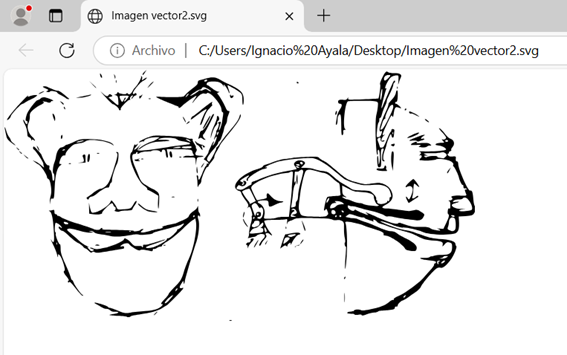
1. Model vector in Inkscape
Step 1: Import the Image
Open Inkscape and go to File > Import to select the image you want to vectorize.
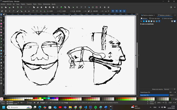
Step 2: Select the Image
Click on the imported image to ensure that it is active.
Step 3: Open the Bitmap Trace Tool
Go to Path > Trace Bitmap... (or use the shortcut Shift+Alt+B).
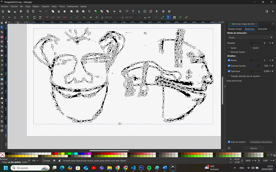
Step 4: Configure the Vectorization Parameters
In the dialog box that appears, you will find several options:
- Brightness Threshold: Ideal for black-and-white or high-contrast images. Adjust the value to determine which parts are converted into vector.
- Edge Detection: Used to highlight the contours.
- Color Detection: Useful if you want to maintain distinct color areas.
Enable the Live Preview option to see how the vectorization will look with the selected parameters.
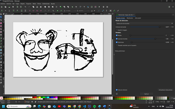
Step 5: Perform the Trace
Once you are satisfied with the preview and the parameters are adjusted, click OK to generate the vector. The trace will overlay the original image.
Step 6: Adjust and Edit the Vector
Select the vector and, if necessary, use the Node Tool to refine contours, remove unnecessary nodes, or smooth out lines. You can move the vector aside to compare it with the original image and ensure the result is as expected.
Step 7: Finalize and Save Your Work
If you no longer need the original image, delete or hide it. Save the result in SVG or another vector format by going to File > Save As....
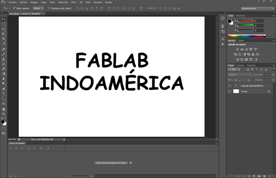
2. Model Raster in Photoshop
Step 1: Open Photoshop and Select the Layer
Open Adobe Photoshop and select the layer you want to rasterize from the Layers panel.
Step 2: Right-click on the Layer
Right-click on the selected layer in the Layers panel. A menu will appear with different options.
Step 3: Choose "Rasterize Layer"
From the context menu, click on "Rasterize Layer" (or "Rasterize Type" if it's a text layer).
Step 4: Edit the Rasterized Object
Now, the object is no longer a vector but a raster image, meaning it consists of pixels. You can apply brushes, filters, and pixel-based effects.

That's it! You have successfully rasterized your object in Photoshop.
3. Model 2D in AutoCAD
Step 1: Workspace Setup
Open AutoCAD and select the Drafting and Annotation workspace.
Ensure the Grid (F7) and Snap to Grid (F9) options are enabled for precise drawing.
Work in millimeters or inches depending on your project requirements.
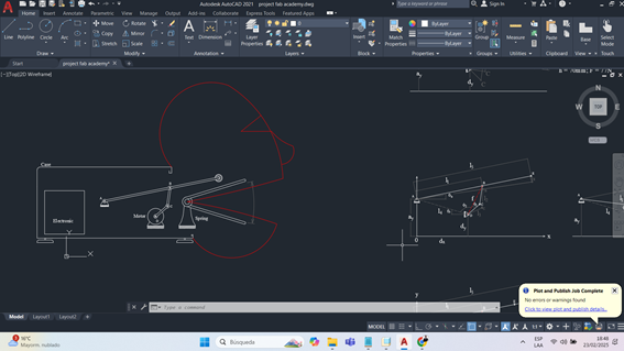
Step 2: Drawing the Mechanism's Bars
Draw the Base of the Mechanism
Use the Line tool (LINE or L) to draw the
fixed base
of the mechanism.
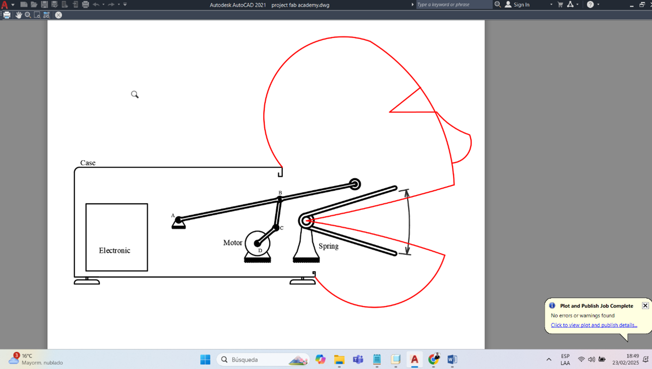
4. Model 3D
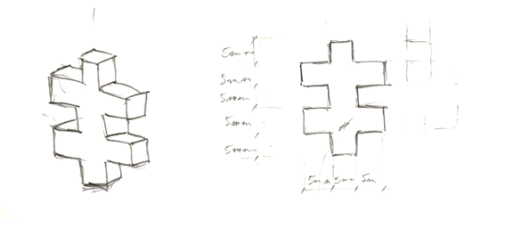
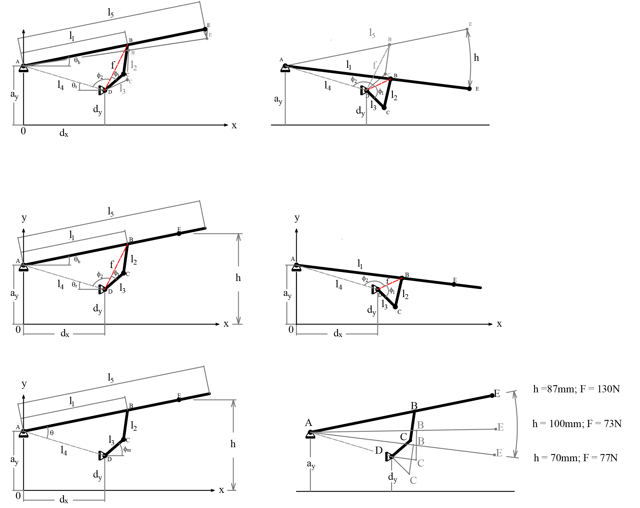
This project consists of the mechanical modeling of a four-bar linkage system designed to control the mouth opening and closing of a puppet. The trajectory of the movement was solved graphically in advance to ensure that the motion replicates a lifelike jaw movement.
The resulting configuration was then modeled in SolidWorks, allowing the full assembly and analysis of the linkage system with an electric actuator.
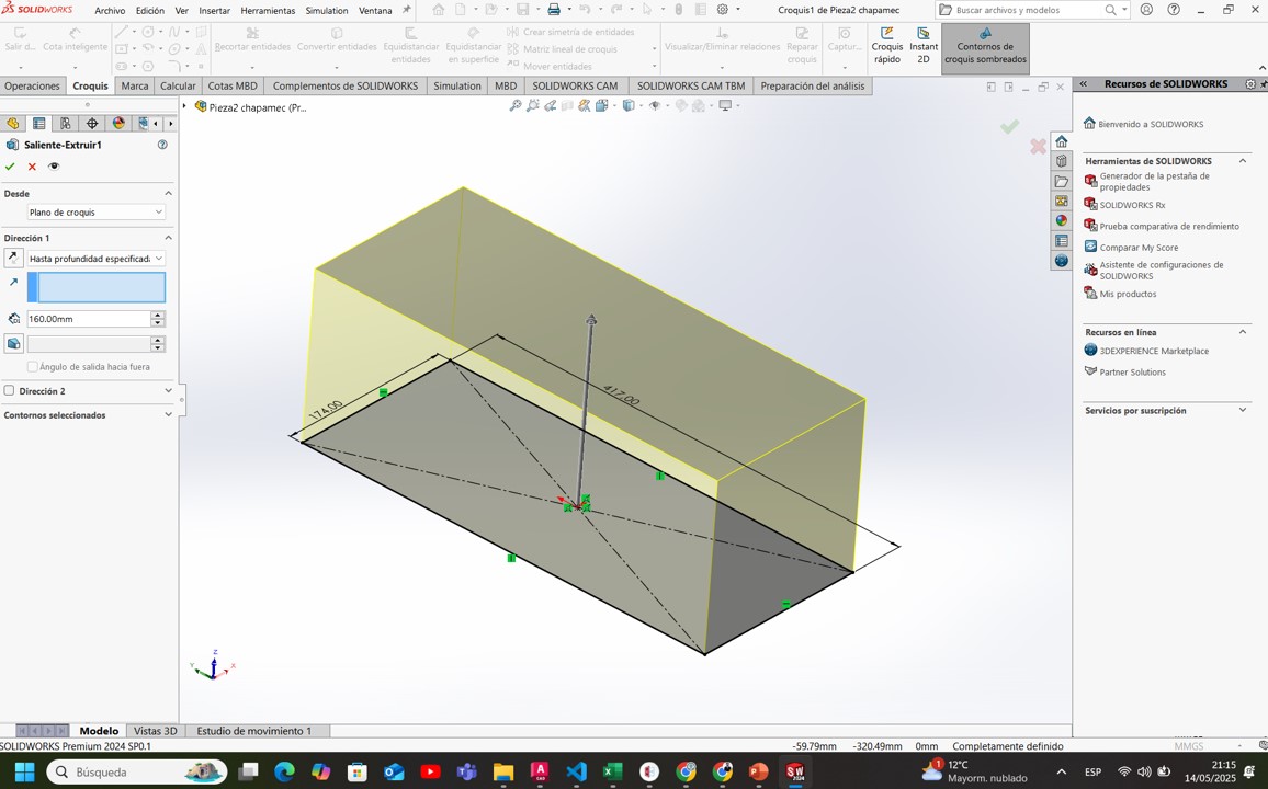
4.1. Base Geometry Creation
The model starts by sketching a rectangle of 71.5 mm x 41 mm. This is extruded to a depth of 160 mm using the Extruded Boss/Base feature to generate the main solid block.
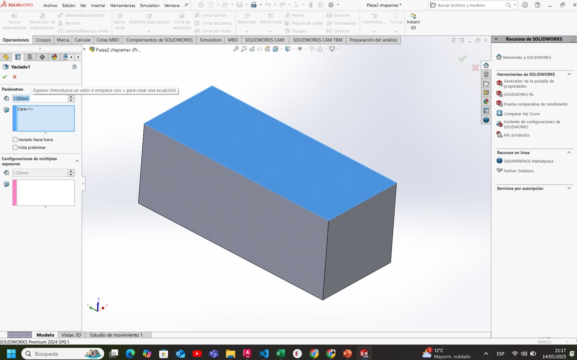
4.2. Shelling the Block
A shell feature is applied to hollow out the solid, leaving 1.5 mm thick walls. The top face is removed to allow internal component housing.
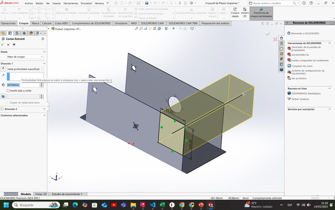
4.3. Perforations and Openings
A new sketch is created on one of the main faces of the block, including several circles and a rectangular profile to represent connection ports and component holes. These are cut through with an extruded cut of 307 mm.
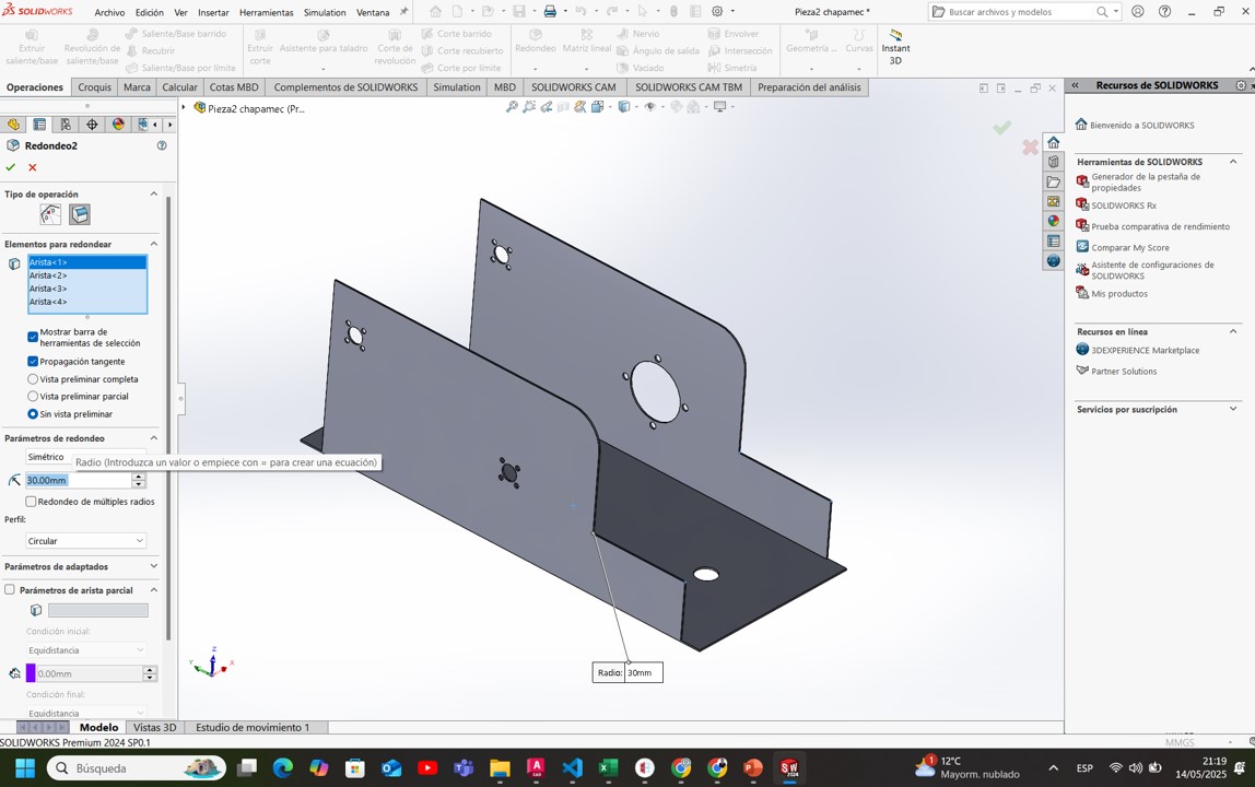
4.4. Edge Filleting
To improve aesthetics and safety, fillets of 30 mm radius are added to the main sharp corners of the structure.
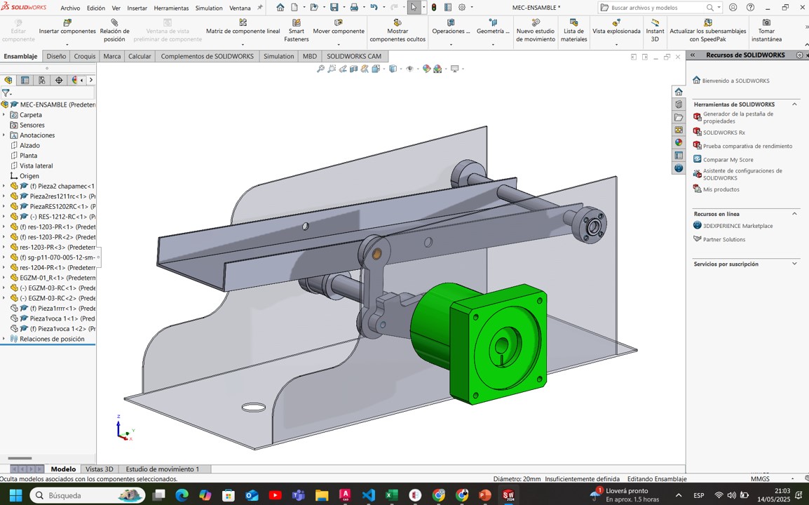
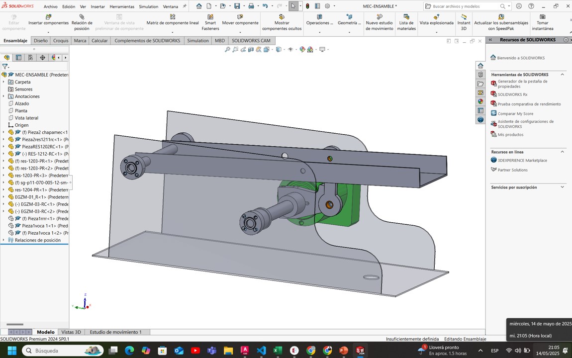
4.5. Mechanical Assembly in SolidWorks
After creating all the required parts, the mechanism is assembled. The main components are:
- A DC motor (green housing) that drives the system
- Shafts and bearings for rotational movement
- The four-bar linkage arm connected to the puppet's mouth
- Support plates and base with fixing points
5. Compressed your image and video
5.1 Image Compression Experience
I worked with original images captured at a high resolution (4000 x 3000 pixels), with file sizes between 3 MB and 5 MB.
Tools Used: GIMP and Blender
To compress images:
- I opened my images in GIMP and exported them using JPEG format, adjusting the quality slider to around 70% to achieve a good balance between file size and image quality.
- Additionally, I experimented with Blender by rendering images and exporting them with lower resolution and compression settings for certain 3D-generated graphics.
After compression, the images were reduced to between 1 MB and 1.5 MB each without significant visual loss.

5.2 Video Compression Experience
I worked with Full HD (1080p) videos, approximately 2 minutes long, with original sizes of around 200 MB each.
Tools Used: HandBrake and ffmpeg
For video compression:
- I used HandBrake to quickly compress videos. I selected the "Fast 1080p30" preset, used the H.264 codec, and set the RF (Quality) value to 22. The final video sizes were about 50 MB.
- I also experimented with ffmpeg via command line, manually setting the video bitrate to 1500 kbps to fine-tune compression parameters.
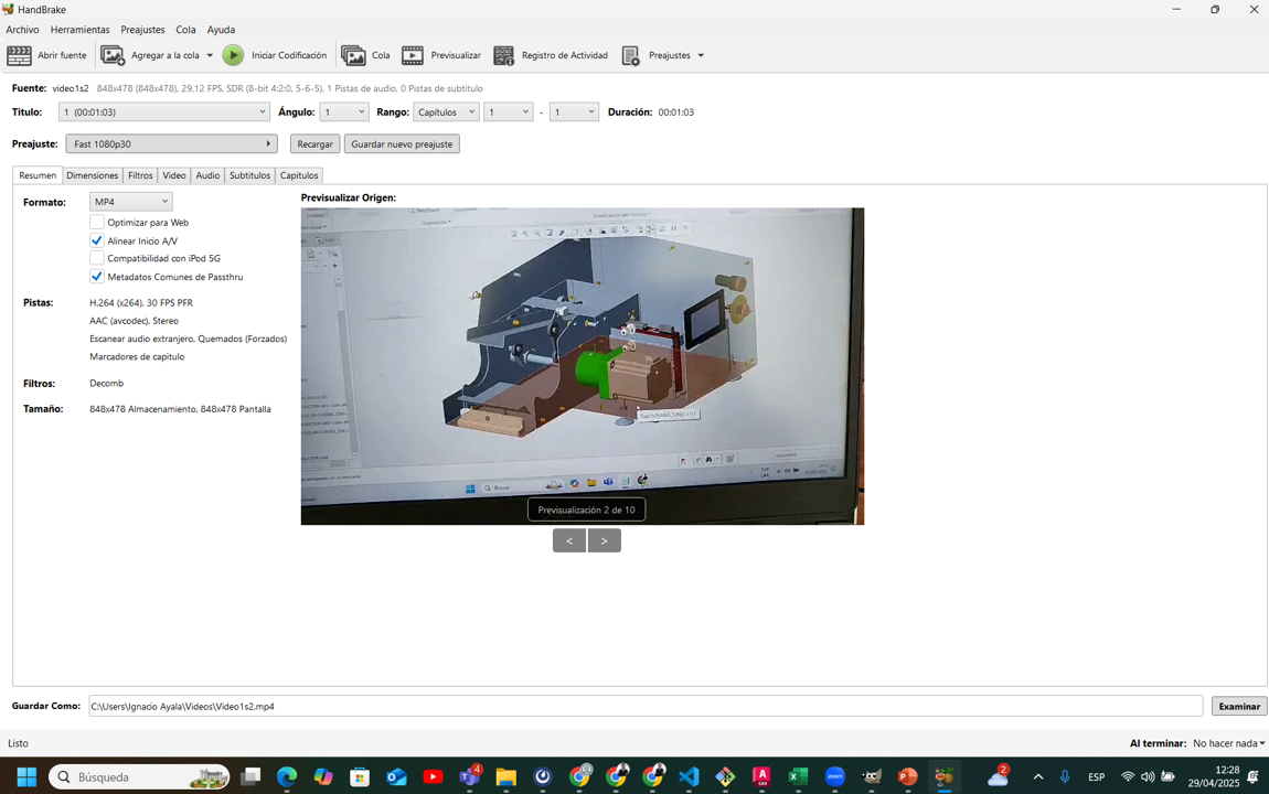
The visual quality after compression remained excellent for web documentation purposes.
Week 2: Conclusion
This week’s activities provided a comprehensive understanding of computer-aided design, including raster and vector modeling, 2D drafting, and 3D modeling. Each step reinforced essential skills in digital modeling, from conceptualization to optimization. The hands-on experience gained through modeling, rendering, and simulating mechanical systems contributed to developing a structured workflow for future projects. By applying different CAD techniques, we achieved a deeper insight into the design process, ensuring accuracy, efficiency, and functionality in mechanical and architectural models.
Resource Download
Click the button below to access and download all available materials.
Download Resources