Week 15: System Integration
Individual Assignment: Design and document the system integration for your final project.
IBM or Apple? Brainstorm
A big question from this year's lecture was to be IBM or Apple. IBM made block-like computer systems, whereas Apple's design came with style. Clearly we see which is the superior.
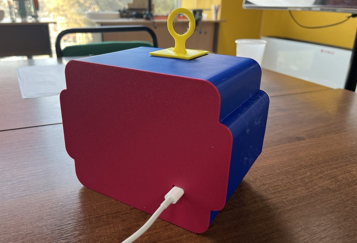
Unfortunately, the first prototype of our project is rather blocklike as IBM's computers:
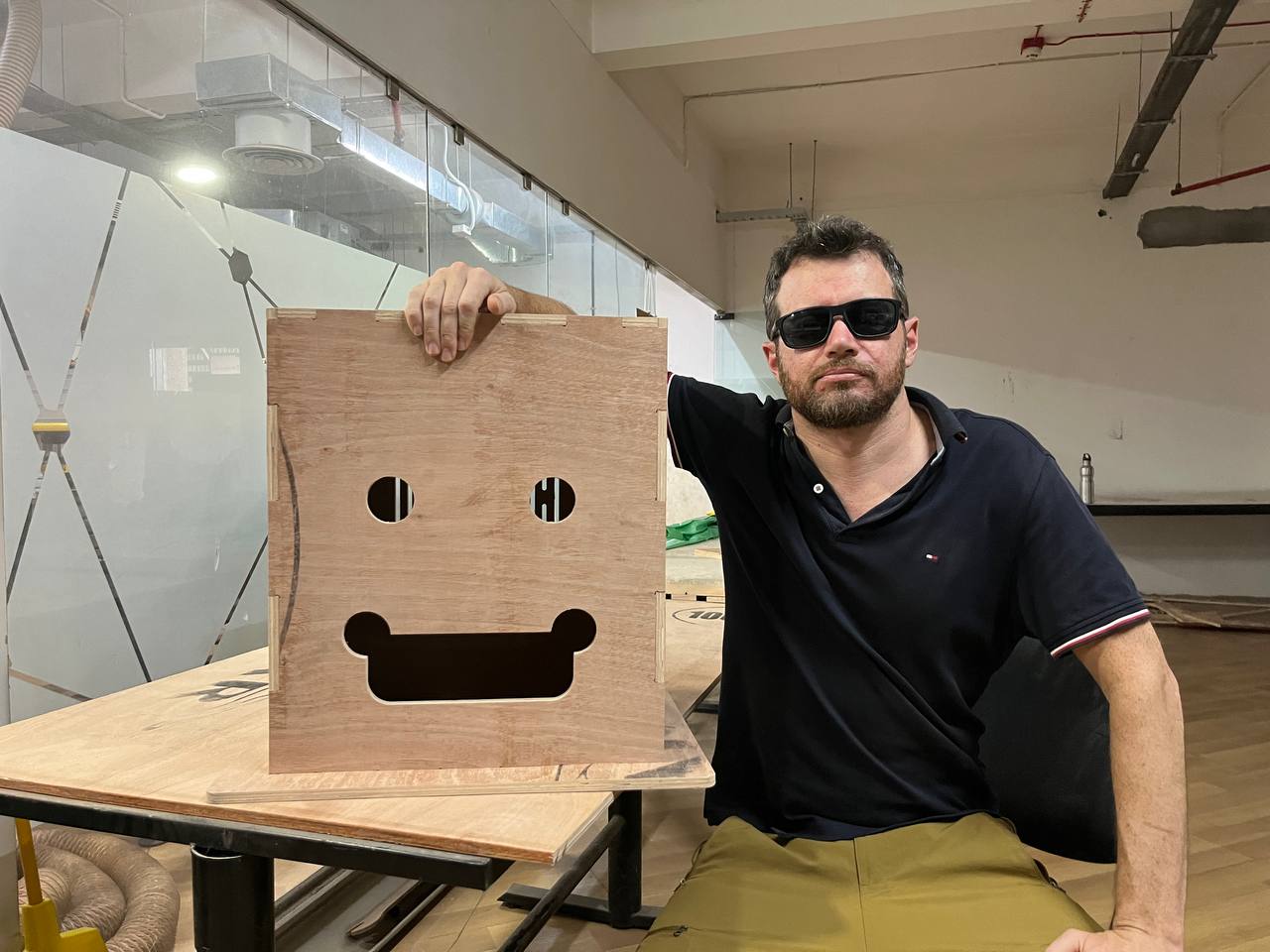
The issue is that the head is unnecessarily big, and lacking grace. It has too much extra space. Let's consider again what we'd need to be inside, and then see how to redesign in a smaller form.
- stack of chocolate candies
- candy dispensing mechanism with motor
- microcontroller/PCB
- RFID card reader
- OLED display (ideal)
- Speaker (ideal)
We might add even more additional features, such as a camera, additional motor to rotate the head or arms, ability to dispense cash or other items, but the minimalistic version of the project can indeed be just a fraction of the original size considered. Although at the moment we will forego a camera module, we will include WIFI for communication.
Small is Beautiful
In fact, the entire project could fit in the model of the CNC project which we cut from cardboard:
As discussed in lecture, there are many ways in which a project can fail. It requires consistent and sustained testing to ensure the project can continue to perform reliably for a long time. We want our project to withstand the wide variety of potential problems. The whole point of the project is that it IS remote, and therefore will need to work very reliably. The smaller size should help it work reliably.
Integration of Face and Dispenser: the two key physical components of the project are the exterior face and interior candy dispenser, we must consider their integration in design. Basically it's a design question of how we will fit the mechansim (with electronics) inside of the head. We can image opening the back of the head and we'd like to see a very neat arrangement of the controller and wires to the sensors, with the motor and dispensing mechanism firmly situated within also. This will be our main task.
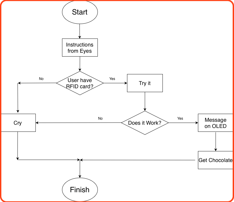
User Flow:
Before continuing, let's consider the user's interaction with the project. Although the project is relatively simple, it is good to think through the process clearly.
Project Functionality:
We must also clearly consider all the peripherals and how they will interact.
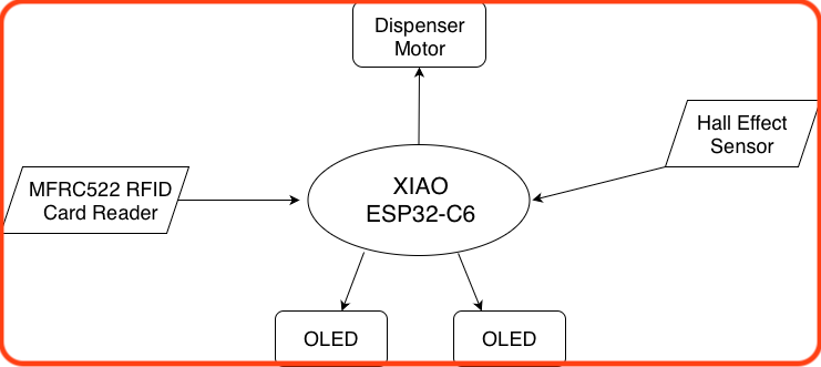
Components:
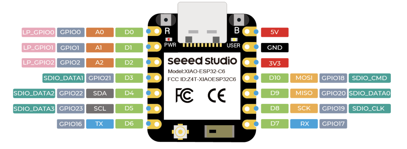
0. XIAO ESP32-C6 Board
The main controller will be the ESP32-C6 recommended by Sheikh Saheen as it contains a WIFI module for communication amongst many beneficial features. The ESP32-C6 provides a large number of ports supporting all the major communication methods, so it should be possible to connect all our input/output devices. However, on further consideration, the available Xiao ESP32-C3 board should suffice, as it will also support the devices we want to include as can be observed in the following pinout. Image source.
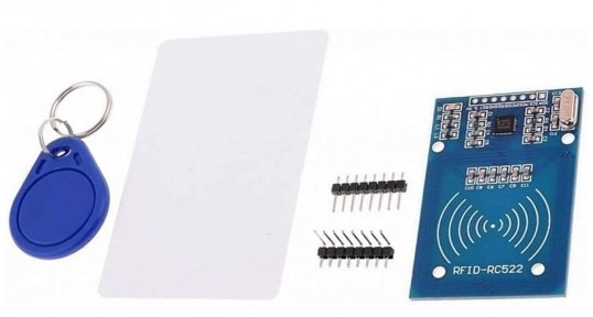
1. MFRC522 RFID Card Reader
We'll use the RC522 which is the standard RFID module available everywhere. RFID cards will be easier to implement than facial recognition as we originally hoped, so in the interest of completing the project in this lifetime we will take this option.
The RC522 module supports all standard methods of communication: UART, I2C, and SPI. However, as SPI is supported and commonly used for it's high we will utilize this option. Anyway, here it is: image credit.
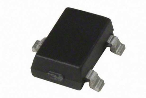
2. Hall Effect Sensor
The hall effect sensor that we used in week nine, is a wonderful, reliable and durable sensor hence perfect for our project. We will use the hall effect sensor here to determine when the motor should stop, that is it should not infinitely rotate and dispense all the candies. Note that in our case we will not be using a stepper motor such as the NEMA17. See the next section for more details. image credit.
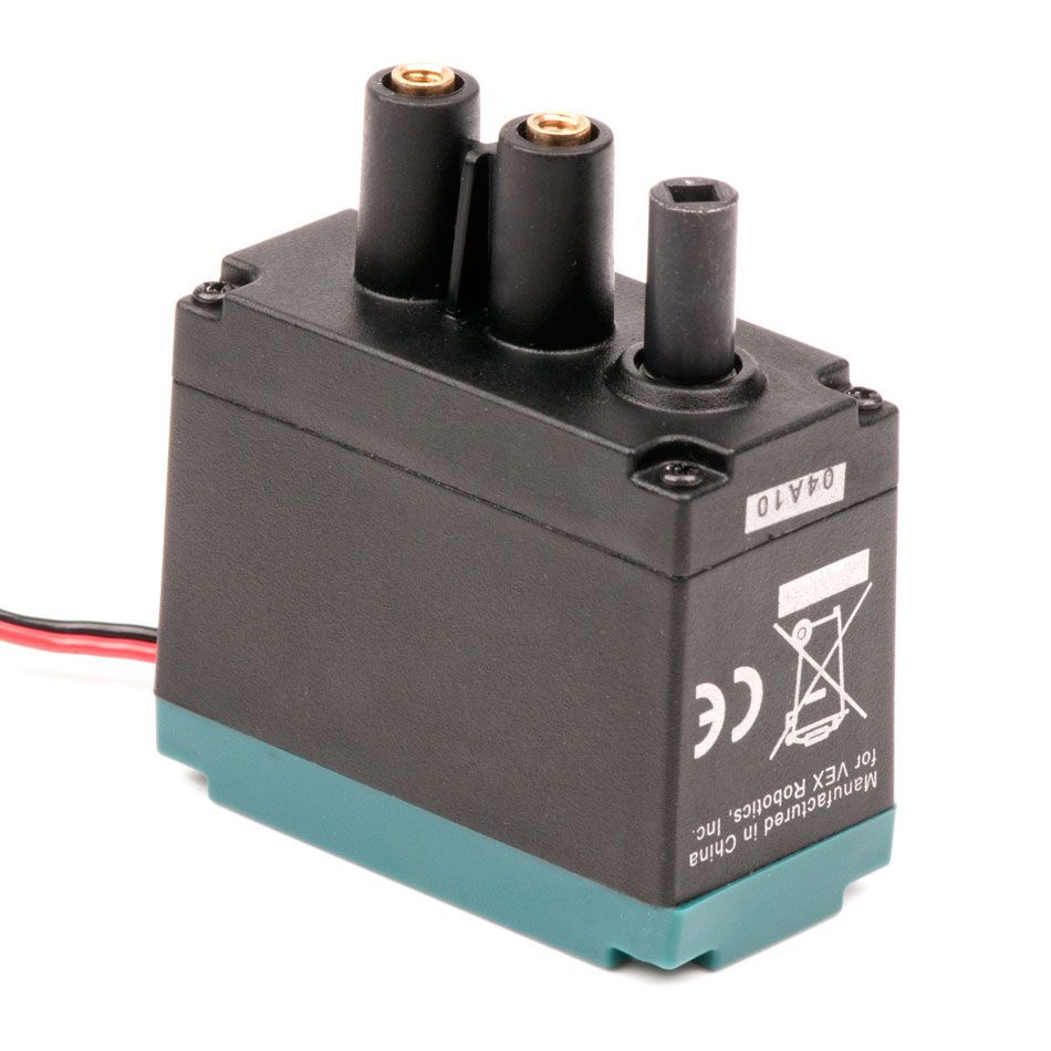
3. VEX Robotics 393 Motor
It happens that we have available to us a very large amount of 393 Motors from VEX Robotics. These are simple 2-wire motors, but also strong, reliable, and easy to fix as needed. These aspects support our ardent desire to produce multiples of our project.
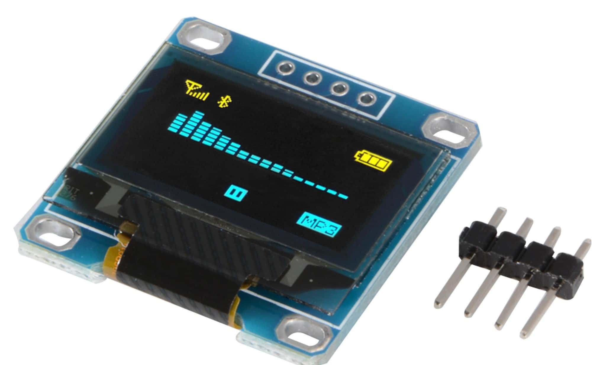
4. OLED displays
Our old and familiar OLED display, full documentation we did in the output week.
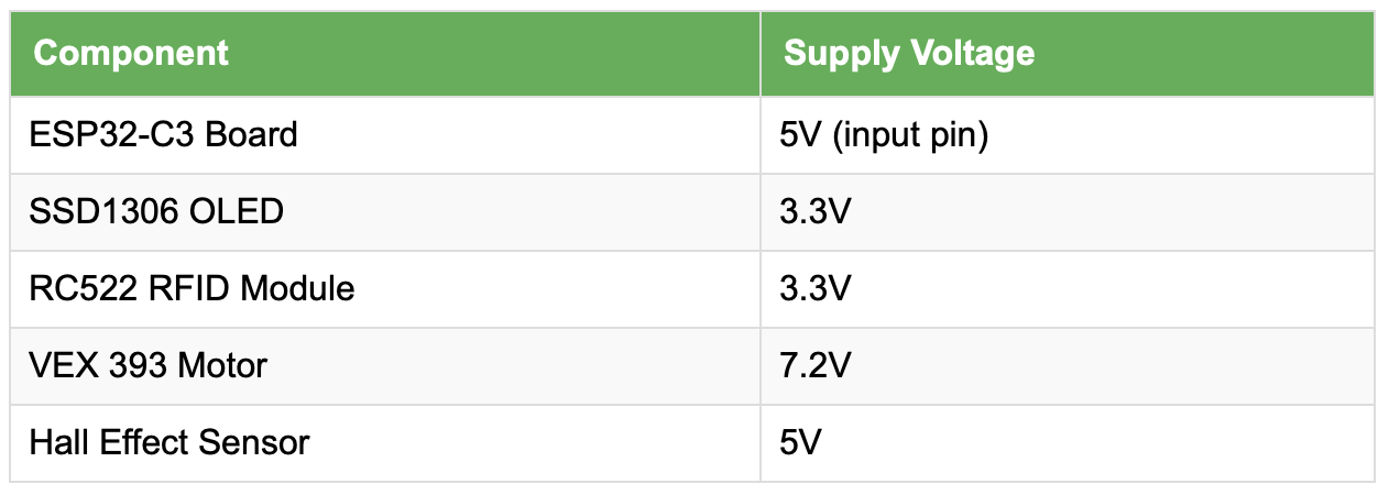
Here's a summary of the components to be integrated with their respective operating voltage
Board & Wiring
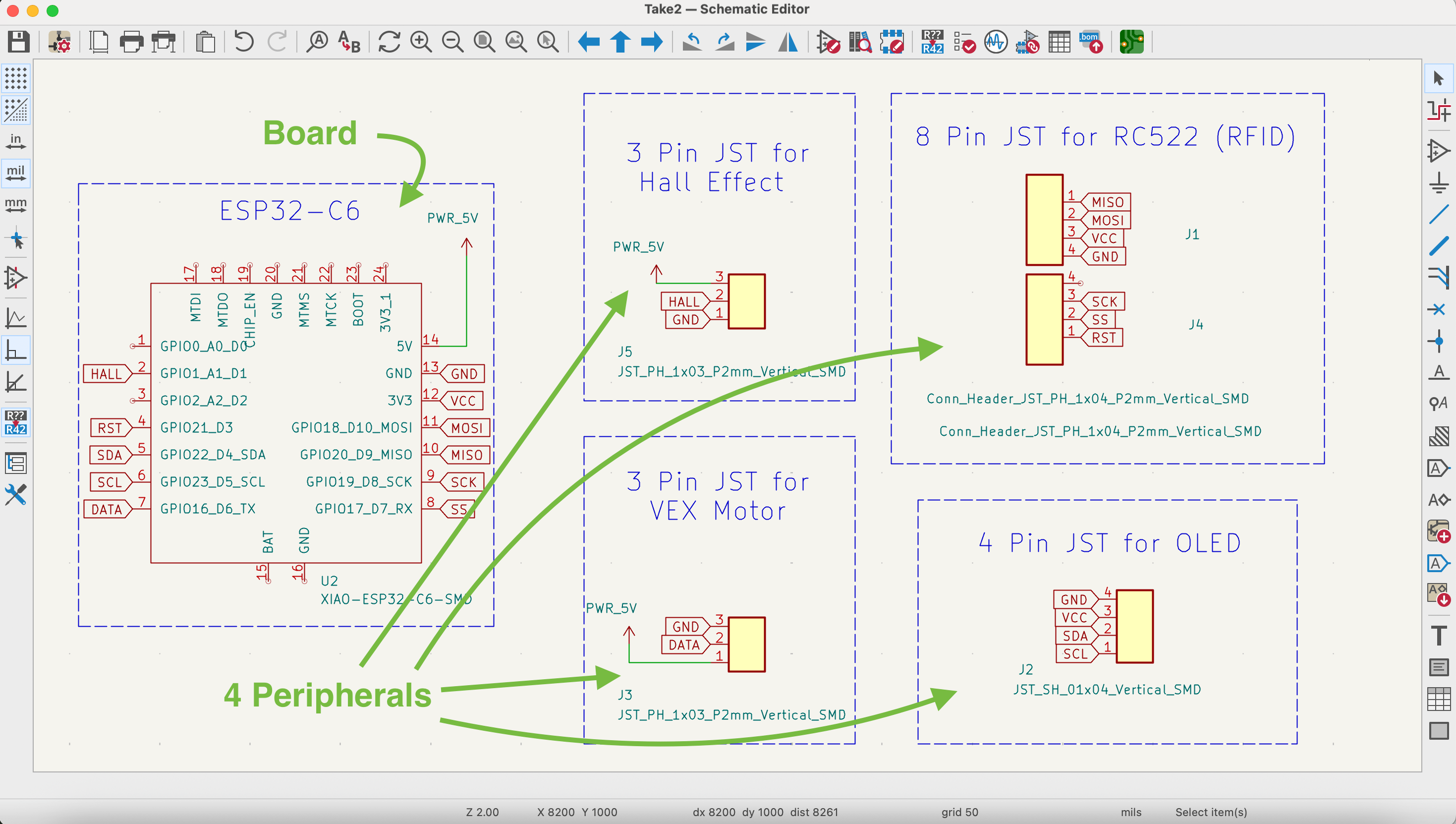
The plan is for one simple main board which will have connections to the other components and peripherals. The different components must be in different locations; specifically the RFID and Hall Effect sensor will be in different locations to receive data, and the OLED eyes and motor will likewise be placed in different locations as output devices. This is why it is logical for all these peripherals to be connected via wires and JST connectors to the main board.
Here's the schematic:
Here's the PCB layout:
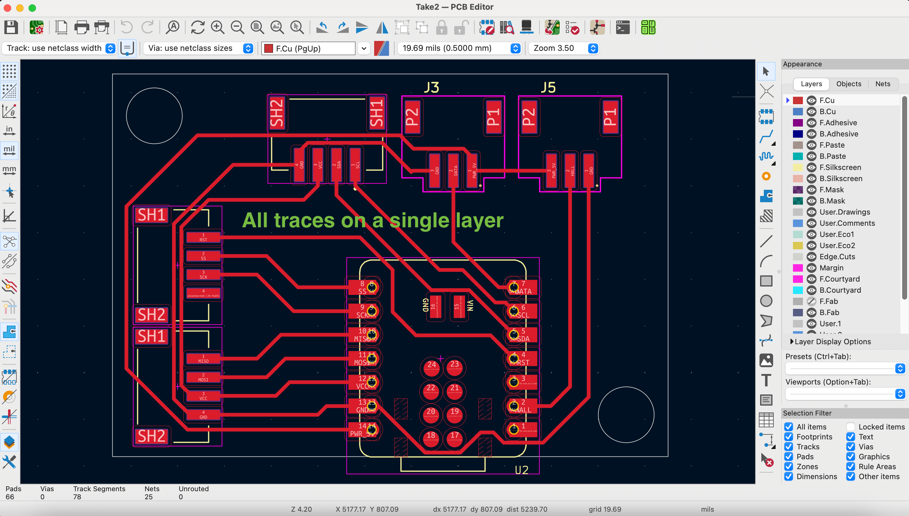
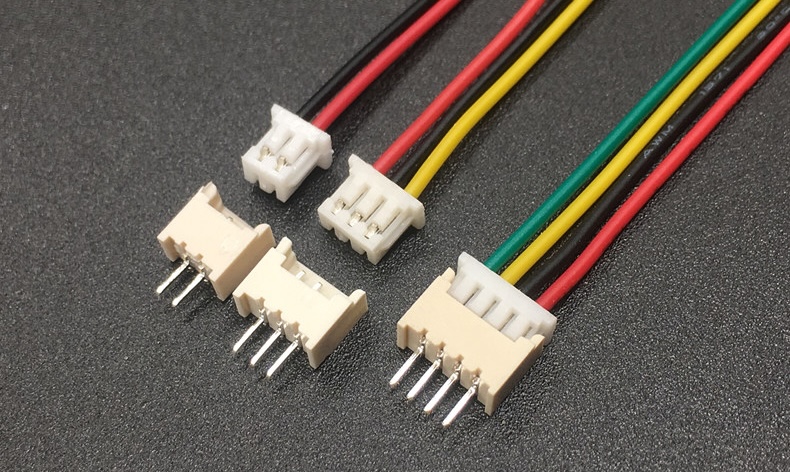
As mentioned we will connect all the peripherals to the main board via JST connectors, either 3-pin or 4-pin varieties. JST stands for "Japan Solderless Terminal", and is a nice way to easily connect and reconnect devices. image credit.
The wires we will cut to the minimal length needed, so as to minimize the risk of mess and disconnections from wires getting stuck in the mechanism. The only exception to this is the wire from the motor which is connected to a wire with a driver and together it getting long. Finally, we should note that we do not want any wire to be visible. The only wire anyone should see is the usb cable giving the powering the project and neatly plugged into the back.
Mechanism
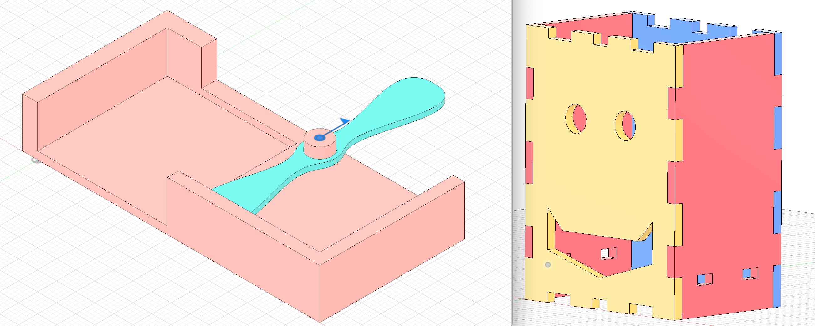
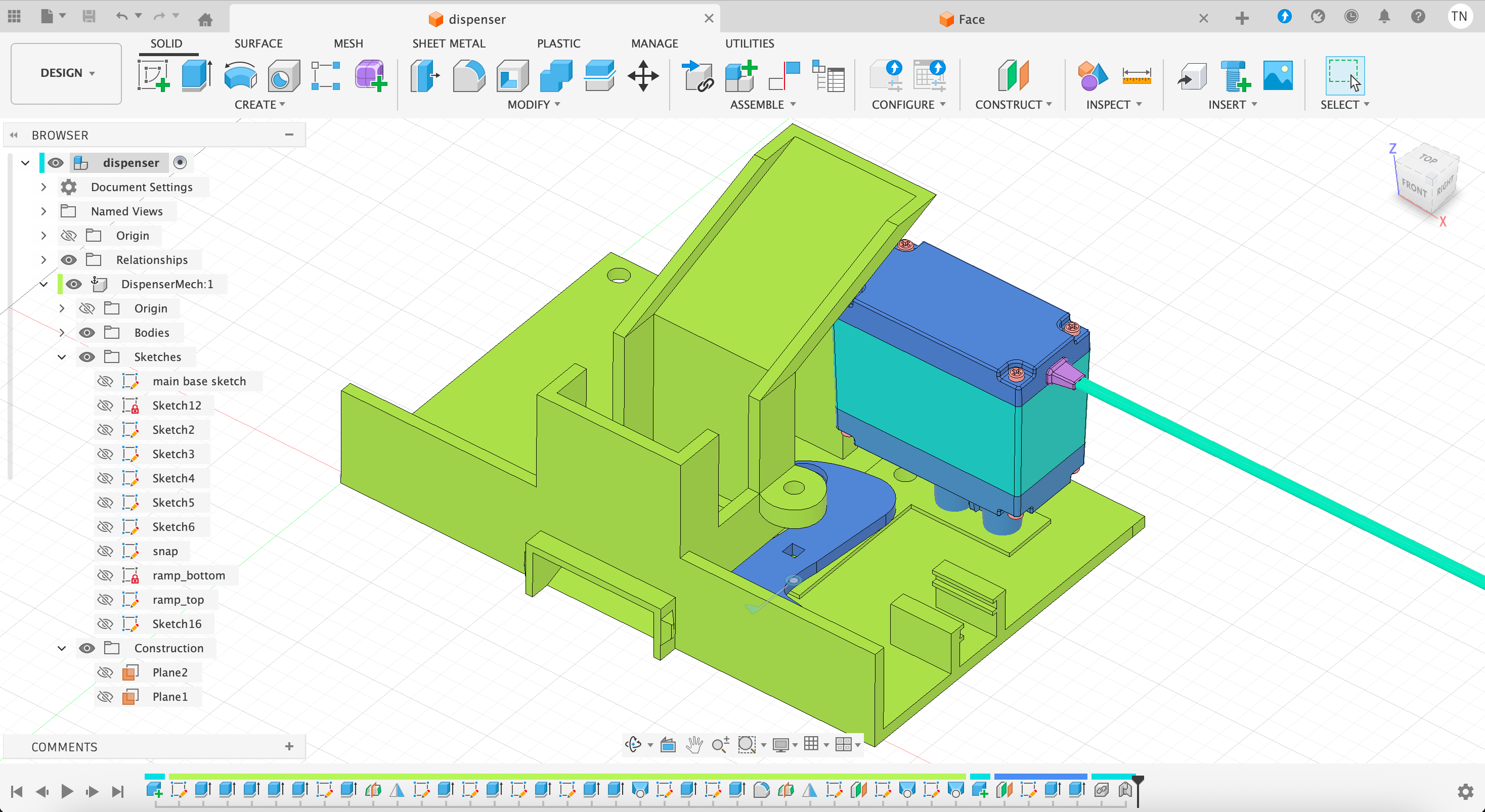
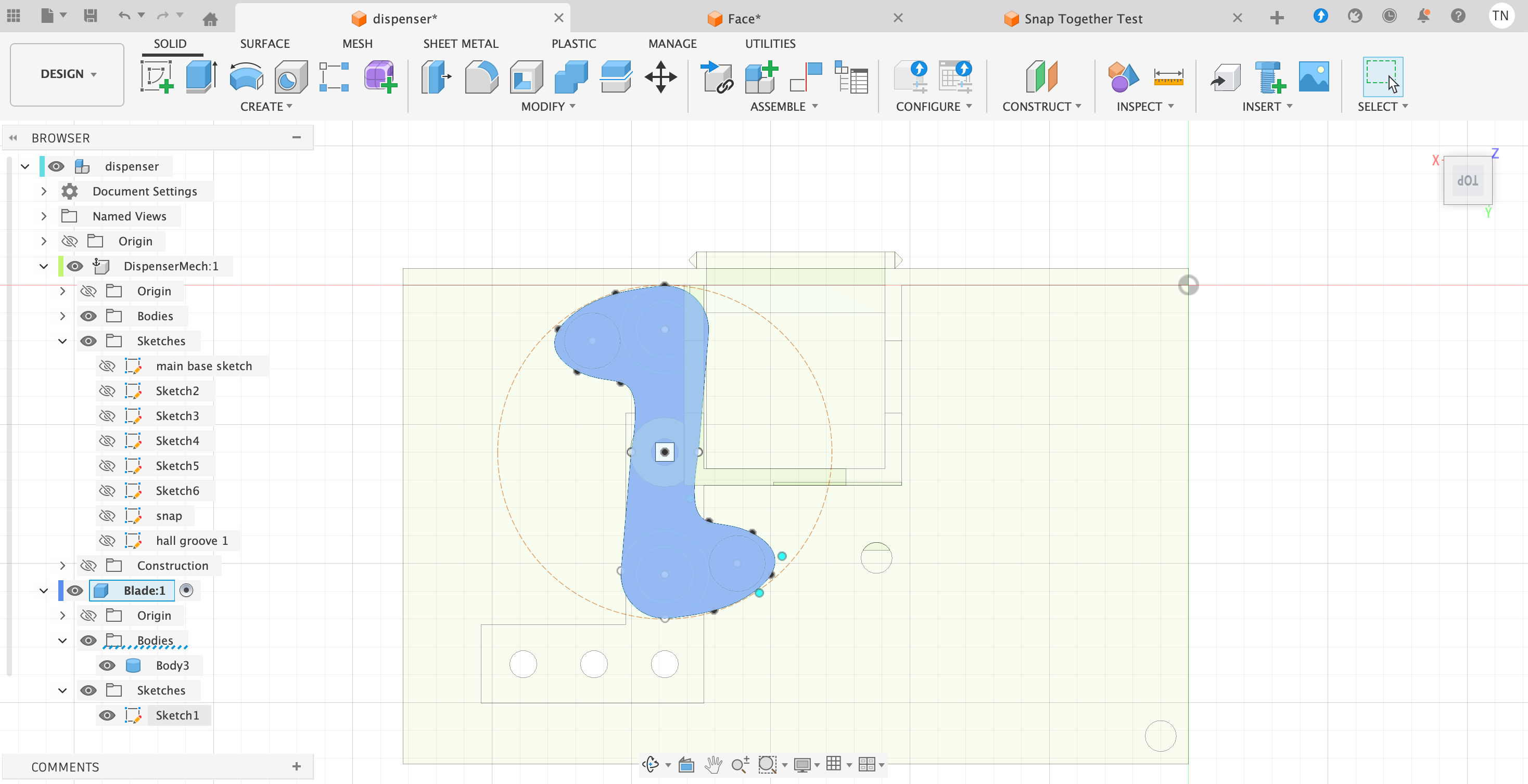
The core objective of the project is to deliver healthy, wonderful, dark Kazakh chocolates, so the mechanism for delivery is most important. The design for the mechanism includes a place for the board and all the peripherals. It also includes a receptacle or cannister for the chocolates. Here is the design we'll print, including the motor and rotating blade, connected and driven by gears underneath.
Here is the plan for the rotating blade. The blade is required to be very precise in terms of fitting within a circle, and the ideal position of the embedded magnet to trigger the Hall Effect.
Here is an early concept animatrion of the rotating blade:
Here is a later animation the full and precise inner body:
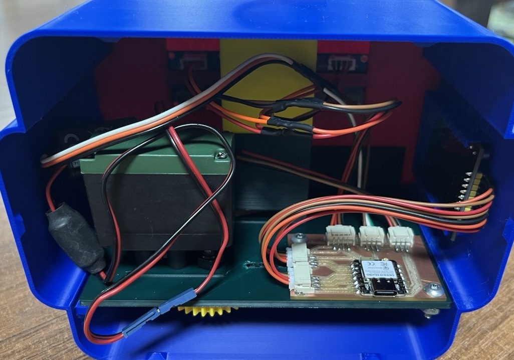
And an even later picture of the real inner body, mechanisms and wires all included:
Methods of Packaging
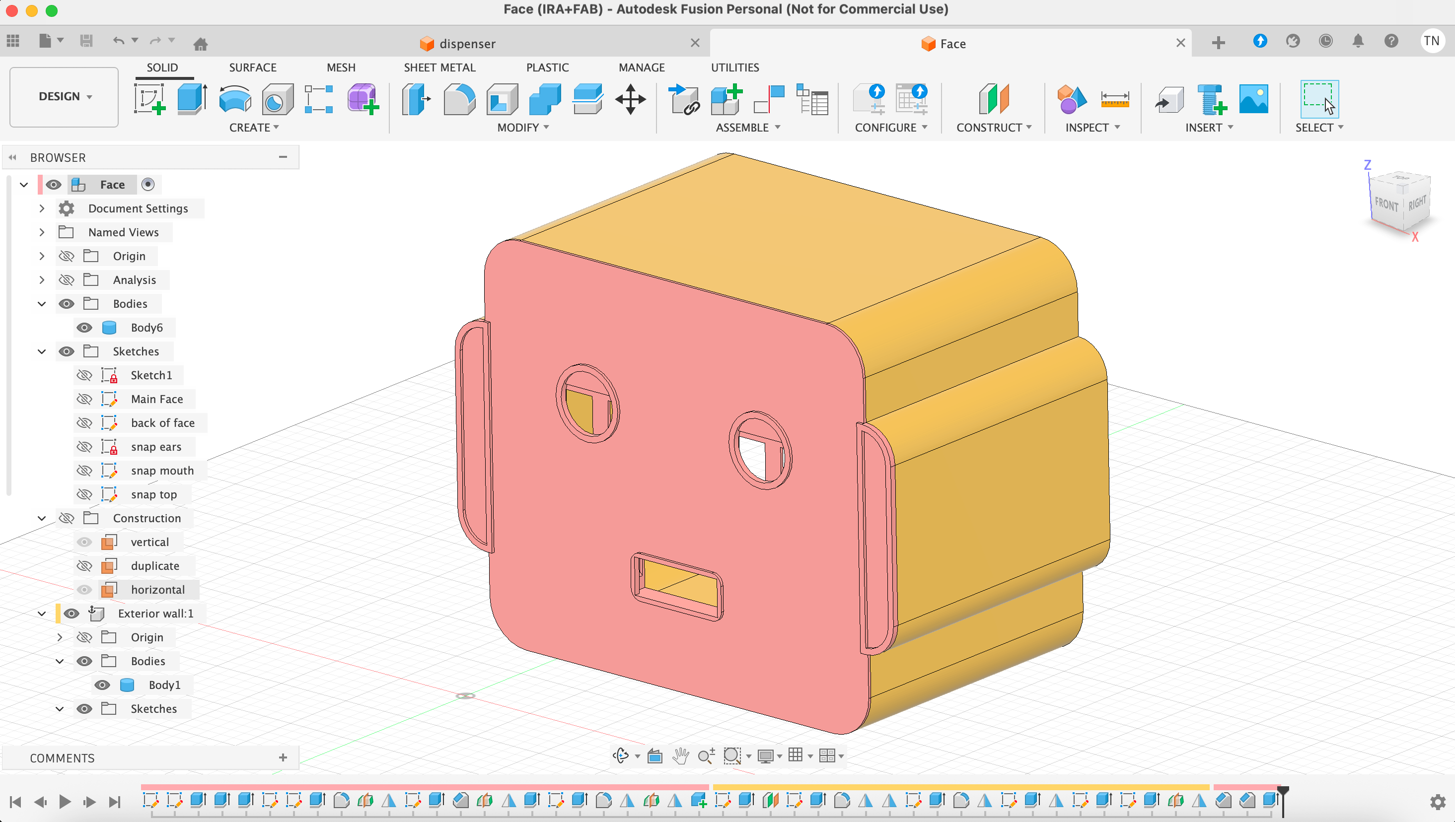
The mechanism was working fine, but subsequently we need to package that within a Robot head, starting with the face, and here's an earlier rendition of that, making it as friendly as possible!
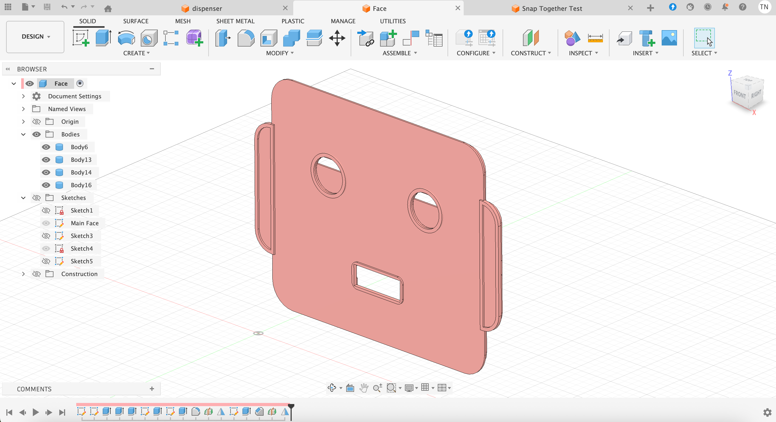
By plan the OLED boards will be integrated into the project as eyes. However, it is not imediately obvious how to make a design to insert them as eyes, due to the size of the OLEDs and their attached wires.
We also need an exterior wall. Here is a rendition of the sides of the head, which Saheen smartly forced me to develop early on. In the process of thinking through design prior to production, realized that a combination of laser-cuttering and 3D-printing as initially planned would be quite difficult to integrate, and this besides the fact that a laser-cut head will always maintain too much of a square and block-like shape.
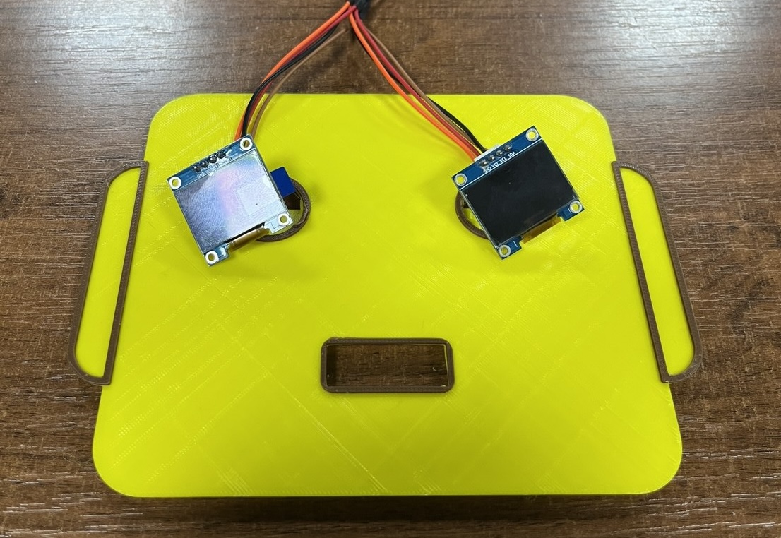
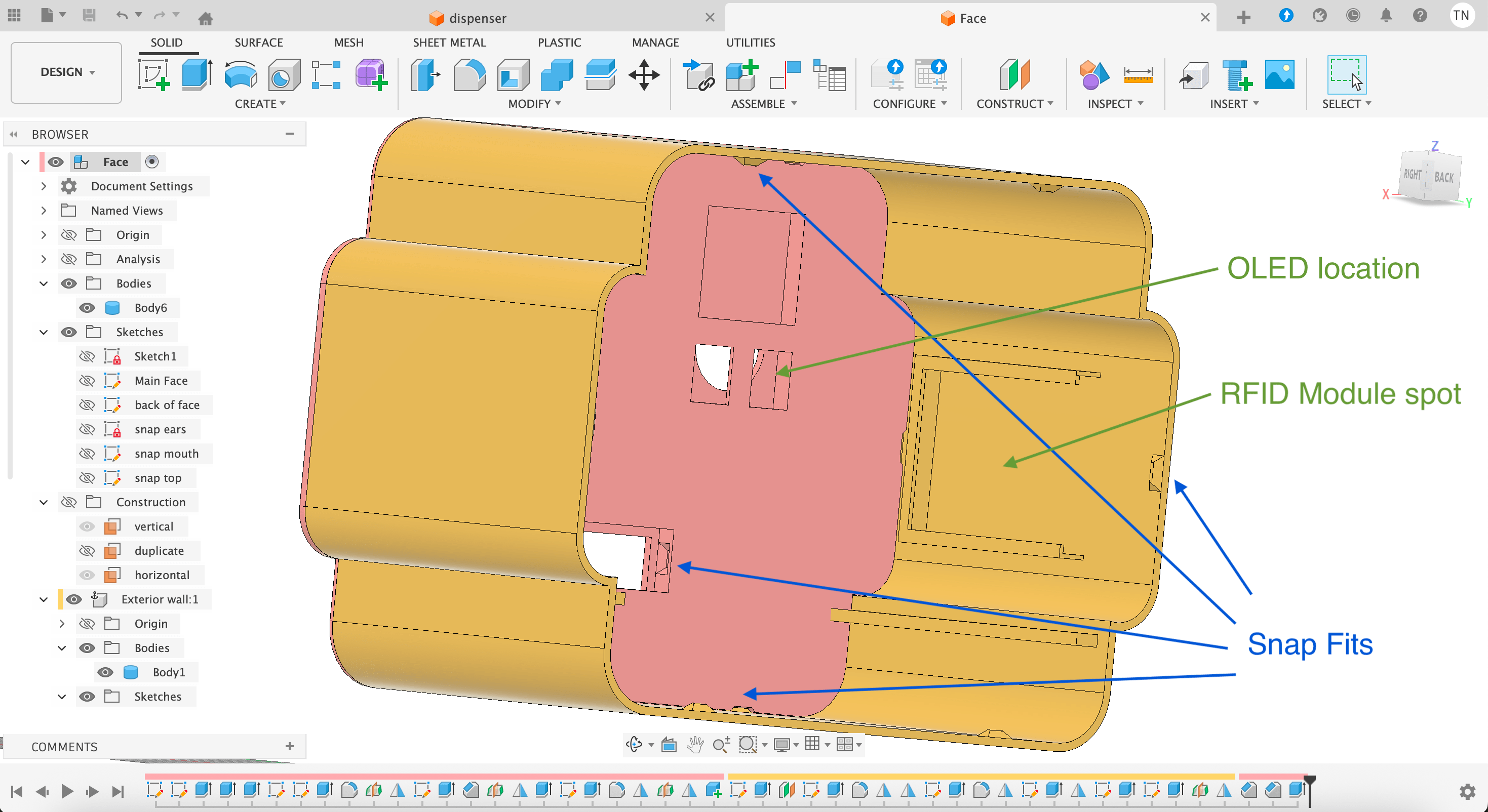
Here is the interior of the Robot head, the face and exterior walls being held together by snap fits, thanks Saheen for recommending us this tutorial tutorial on that! We also see the built-in slots for the OLED eyes and the RFID card reader in the ear!
Programming
By plan we will program in the Arduino IDE as we now have some experience with it, it supports the XIAO ESP32-C6 board, and has libraries for all the peripherals in our project.
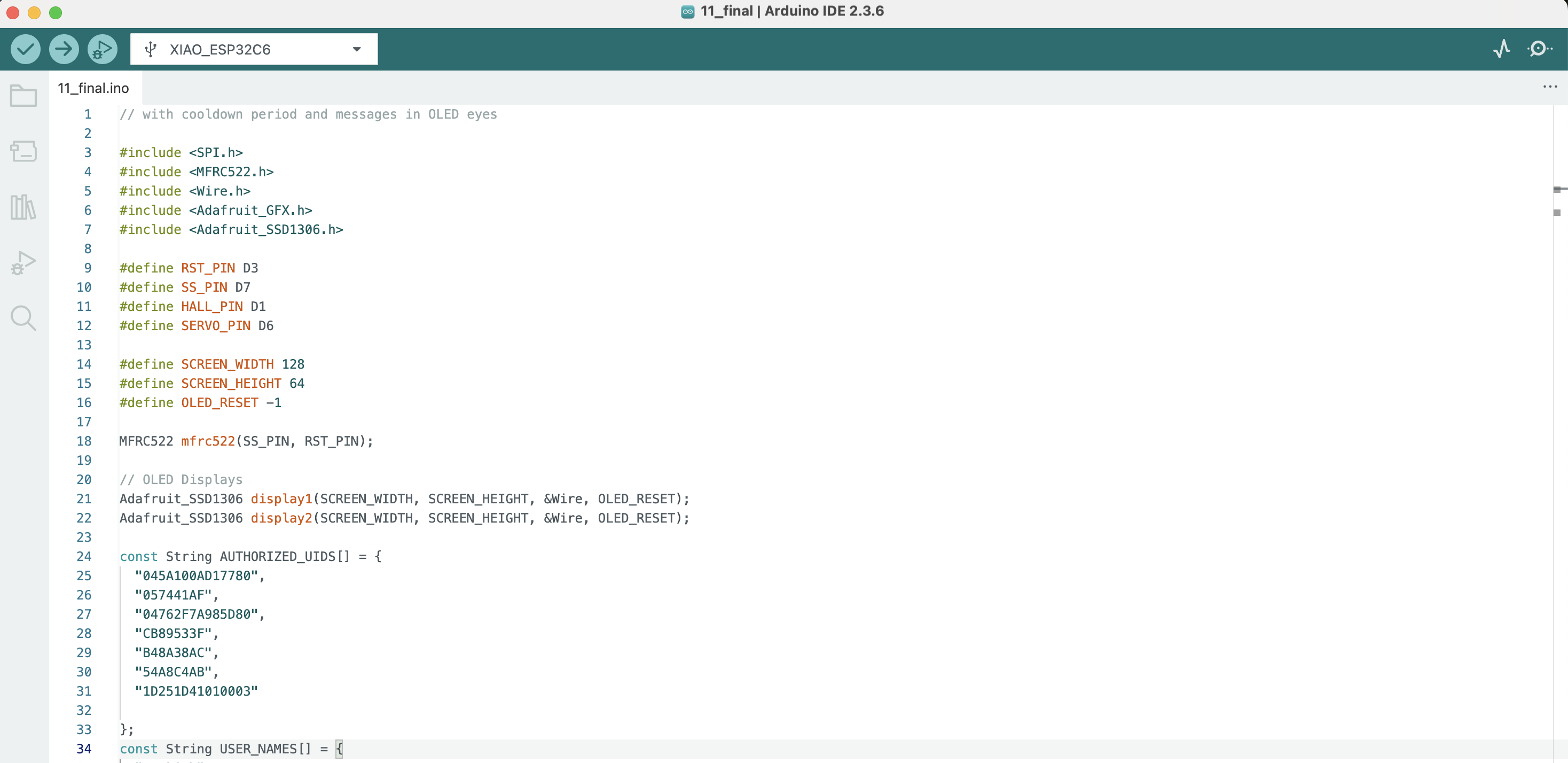
We've already progammed a few of the peripherals separately in the Arduino IDE, the main task now is to integrate those programs for all the devices to interact in a meaningful way.
Subtractive Processes
We'll also need a way to incorporate subtractive processes in our work. One way to glorify the project and keep the ejected chocolates from falling on the ground is to create a small laser-cut platform on which our friendly Robot head can sit.
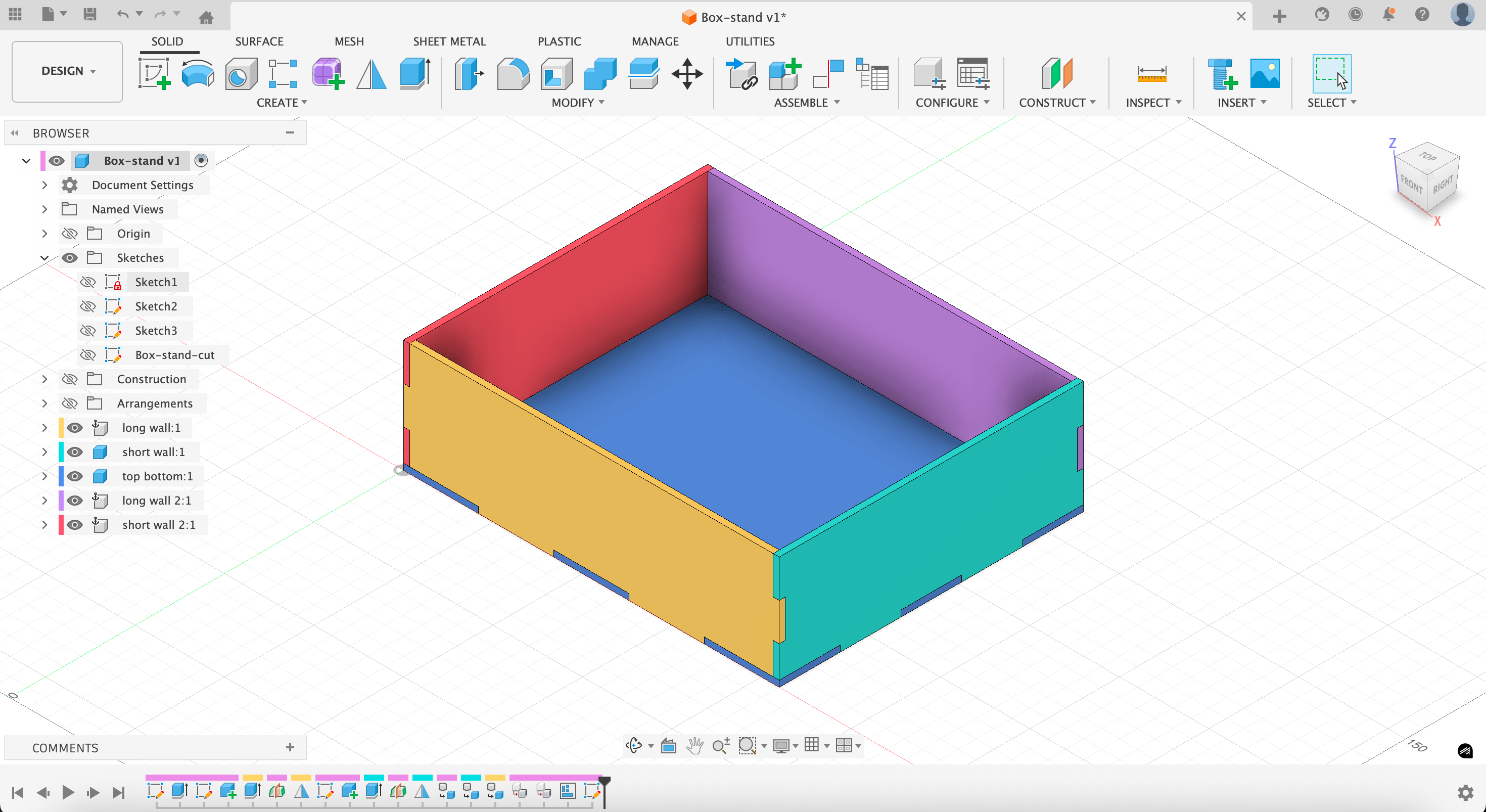
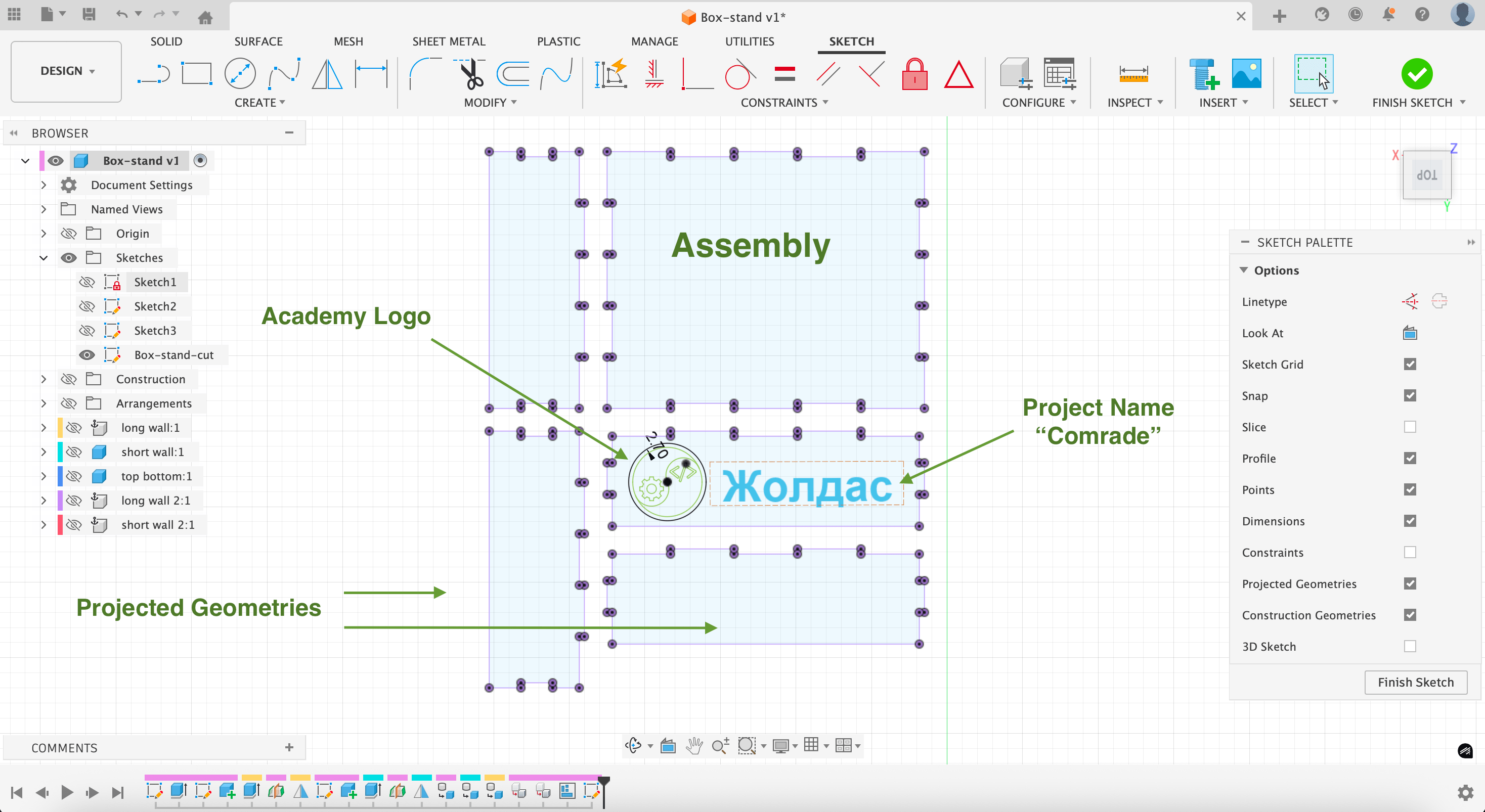
Here's the assembly prepared for laser cutting:
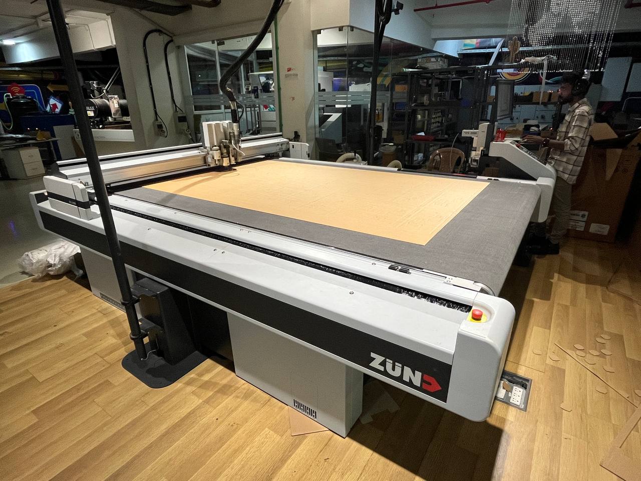
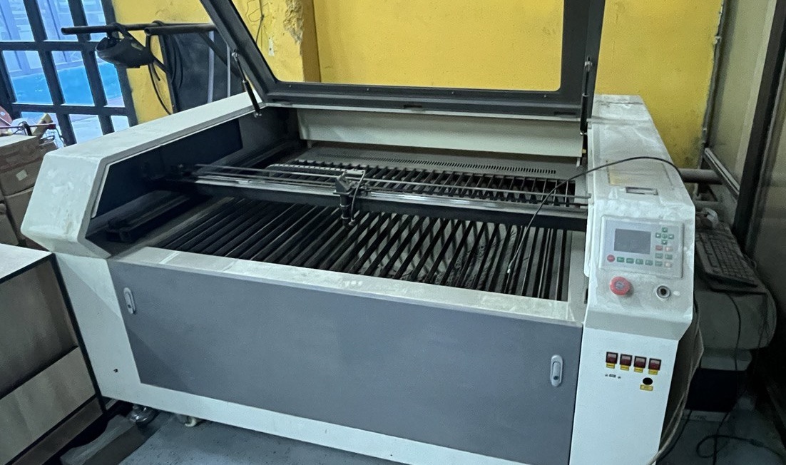
And a vintage laser-cutter we have the opportunity to use:
Design Files
Face (Fusion 360)Dispenser (Fusion 360)
Snap Fit Test (Fusion 360)