Week 10: Output Devices
Group Assignment (link): measure the power consumption of an output device
Individual Assignment: add an output device to a microcontroller board you've designed, and program it to do something.
Group Assignment
In the group assignment, we were meant to measure the power consumption of an output device. For background knowledge, Saheen suggested a fine tutorial which thoroughly documents the fundamentals of the topic.
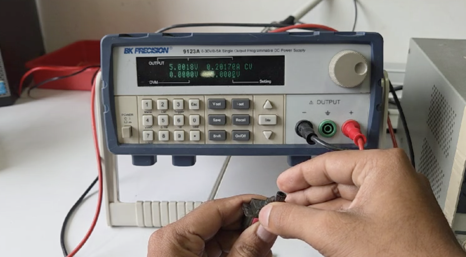
As a group we measured the power consumption of a servo motor by hooking it to the power supply module at 5V. As can be seen from the screen-grab below, the power supply module displays the current, allowing us to measure the power supply by multiplying the Voltage x Current. At this particular moment the display shows 5 V x 0.2 amps, giving a resulting power consumption of 1 Watt. The power varies over time, especially here as it depends on the physical resistance we place on the servo motor. Refer again to the group assignment page for full details.
OLED SSD1306
Getting Started
A display is a very important output and potentially helpful for my project. Our lab has this display available. It measures 0.96 inches (diagonally), and has display colors of yellow and blue. It is called SSD1306; image below is sourced from here, and its documentation may be found here.

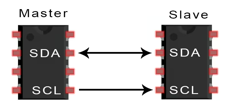
We can note that it has 4 pins, and they are labeled GND (ground), VCC (power), SCL (serial clock) and SDA (serial data). The SCL and SDA pins indicate that I2C will be the method of communication, which means that the instructions for what to display will be communicated through those pins. In particular the data is transmitted via the data line, sycronously with the time which is communivated along the serial clock line. The following image was sourced from here.
Dr Neil shared a similar board he made, using this display and the ATTiny45 as the microcontroller. It appear that he has exactly the same module as we do, same 4 pins, and coloring as well. Credit for image to him. This is very helpful to get started, thanks Dr. Neil!

Examining the board in further detail, we notice a couple other components we must make sure to include in our schematic. First of all, there are pull-up resistors on the SDA and SCL lines. This is needed because the microcontroller can only pull the lines low, but can't drive them high. We also note a capacitor which can be placed between Ground and VCC. When using the OLED its good to have a capacitor since the power requirements are not stable, when the screen is cleared or new elements put on display, the power requirements will increase for that moment. Again, credit for image to Dr. Neil.

Our next task is to choose an appropriate board. We do not have the ATTiny45, however we do have the ATTiny1614. Just because we have a board, however, doesn't necessarily mean its a good choice. However, looking at the data sheet, and examining the schematic we see that it has the appropriate pins for the task and communication. We all understood why it is called 1614.


Designing and Creating the Board
Following the usual procedure in KiCad, we start with the schematic. Besides the ATTiny, we'll need 4 holes for the OLED, 6 header pin for programming and then just a few other components noted above (2 resistors and a capacitor).

Then the PCB editor, check the design rules. We checked, we pass, except for the 4 holes, but they are special as we will be inserting the SSD1306 module right there.

Finally, check out the 3D view! All the components are present. Looks normal.

Now as usual we use gerber-to-png tool to prepare for milling. There will be 3 files we'll need to use for that process: the traces, the drill, and the outline. We'll run them in that order on the machine using Mods. If you look carefully, in the screenshot below, you'll see that there are no drill holes in the drill file. That's because in the file the holes for drilling are only 0.75 mm across, however this is not possible where the bit is 1/32"=0.79 mm. We changed that later.

The board was cut properly, we gathered the other components, and now ready to solder!!

Soldering successfully complete. Here is the completed project:


Programming the Board
We'll program in the Arduino IDE. Setting up we need to change a few things under 'Tools'.

We must also ensure that appropriate libraries are there for the microcontroller to deal with the device in question. Research brought us to discover the U8g2 library, which was easy to install, and should be helpful.

Here is the first (very basic) program. It uses the U8g2 library which we just installed.
#include <Arduino.h>
#include <U8g2lib.h>
#include <Wire.h>
// Constructor for SSD1306 128x64 OLED with hardware I2C
// U8G2_R0 = no rotation, U8X8_PIN_NONE = no reset pin
U8G2_SSD1306_128X64_NONAME_F_HW_I2C u8g2(U8G2_R0, /* reset=*/U8X8_PIN_NONE);
void setup() {
// Initialize I2C (Wire) - megaTinyCore uses default pins PA1 (SDA) and PA2 (SCL)
Wire.begin();
// Initialize the display
u8g2.begin();
}
void loop() {
u8g2.clearBuffer(); //clears the screen
u8g2.setFont(u8g2_font_6x13_tr); //sets font size
u8g2.drawStr(0,30, "Great job, Tom!"); //displays text from a position
u8g2.sendBuffer(); //sends the content to the screen
}
S.I.B.I.N. is a cool character, he showed me Lopaka. Lopaka is a cool website that helps you write code for such displays using the U8g2 library. You can draw, enter text, insert images - and it generates the required code!! So cool.

Here is a program using Lopaka. Basically it generates coordinates of points to be drawn - in particular pay attention to the 2 new lines of the program just prior to "void setup())"
#include <Arduino.h>
#include <U8g2lib.h>
#include <Wire.h>
// Constructor for SSD1306 128x64 OLED with hardware I2C
// U8G2_R0 = no rotation, U8X8_PIN_NONE = no reset pin
U8G2_SSD1306_128X64_NONAME_F_HW_I2C u8g2(U8G2_R0, /* reset=*/U8X8_PIN_NONE);
static const unsigned char image_hand_thumbs_up_bits[] = { 0x00, 0x08, 0x00, 0x14, 0x00, 0x14, 0x00, 0x12, 0x00, 0x0a, 0x00, 0x09, 0x80, 0x7c, 0x5f, 0xc0, 0x31, 0xa0, 0x11, 0xc0, 0x11, 0xa0, 0x11, 0xc0, 0x11, 0xa0, 0x15, 0x40, 0x71, 0x60, 0x9f, 0x3f };
static const unsigned char image_hourglass3_bits[] = { 0x00, 0x00, 0x00, 0xe0, 0xff, 0x0f, 0x20, 0x00, 0x08, 0xc0, 0xff, 0x07, 0x80, 0x00, 0x02, 0x80, 0x00, 0x02, 0x80, 0x00, 0x02, 0x80, 0x00, 0x02, 0x00, 0x01, 0x01, 0x00, 0x82, 0x00, 0x00, 0x44, 0x00, 0x00, 0x28, 0x00, 0x00, 0x28, 0x00, 0x00, 0x44, 0x00, 0x00, 0x92, 0x00, 0x00, 0x39, 0x01, 0x80, 0x7c, 0x02, 0x80, 0xfe, 0x02, 0x80, 0xfe, 0x02, 0x80, 0x00, 0x02, 0xc0, 0xff, 0x07, 0x20, 0x00, 0x08, 0xe0, 0xff, 0x0f, 0x00, 0x00, 0x00 };
void setup() {
// Initialize I2C (Wire) - megaTinyCore uses default pins PA1 (SDA) and PA2 (SCL)
Wire.begin();
// Initialize the display
u8g2.begin();
}
void loop() {
u8g2.setFontMode(1);
u8g2.setBitmapMode(1);
u8g2.setFont(u8g2_font_6x13_tr);
u8g2.clearBuffer();
u8g2.drawStr(28, 10, "Great job!");
u8g2.sendBuffer();
delay(500);
u8g2.clearBuffer();
u8g2.drawXBM(40, 21, 16, 16, image_hand_thumbs_up_bits);
u8g2.sendBuffer();
delay(500);
u8g2.clearBuffer();
u8g2.drawXBM(47, 30, 24, 24, image_hourglass3_bits);
u8g2.sendBuffer();
delay(1500);
}
One of the next obvious things to do is loop text, and in the program below we successfully do it. Scrolling left to right because we read from left to right, at least in English. There are a few issues. One issue is the speed. It's slow even with delay at 1 ms. To solve this we increment the pixel displacement in each iteration by 3 instead of 1. That makes it 3 times faster. Another issue is to know how far we need to scroll. In other words, it is not clear the total length in the X-direction of a custom message. We use trial and error.
#include
#include
#include
// Constructor for SSD1306 128x64 OLED with hardware I2C
// U8G2_R0 = no rotation, U8X8_PIN_NONE = no reset pin
U8G2_SSD1306_128X64_NONAME_F_HW_I2C u8g2(U8G2_R0, /* reset=*/U8X8_PIN_NONE);
void setup() {
// Initialize I2C (Wire) - megaTinyCore uses default pins PA1 (SDA) and PA2 (SCL)
Wire.begin();
// Initialize the display
u8g2.begin();
}
void loop() {
u8g2.setFont(u8g2_font_logisoso38_tr); //sets font size
for (int i=128; i>-500; i=i-3){
u8g2.clearBuffer(); //clears the screen
u8g2.drawStr(i,64, "Follow MakerKootam!"); //displays text from a position
u8g2.sendBuffer(); //sends the content to the screen
delay(1);
}
}
Check out the result and Follow MakerKootam!
NEMA motor
NEMA17: part 1 - Introduction
Rayan has some great documentation for the NEMA17 stepper, including a brilliant schematic diagram and other resources.
Brief background on NEMA17 Stepper motor. It is a standard stepper motor commonly used in a wide variety of different machines but perhaps most famous for use in 3D printers. It is called 17 because it is a block with square head measuring 1.7 inches. It comes in both 4 and 6 wire varieties, but we have the 4-wire type which is great because that's easier. Each step measures 1.8 degrees, so a full rotation consists of 200 steps.
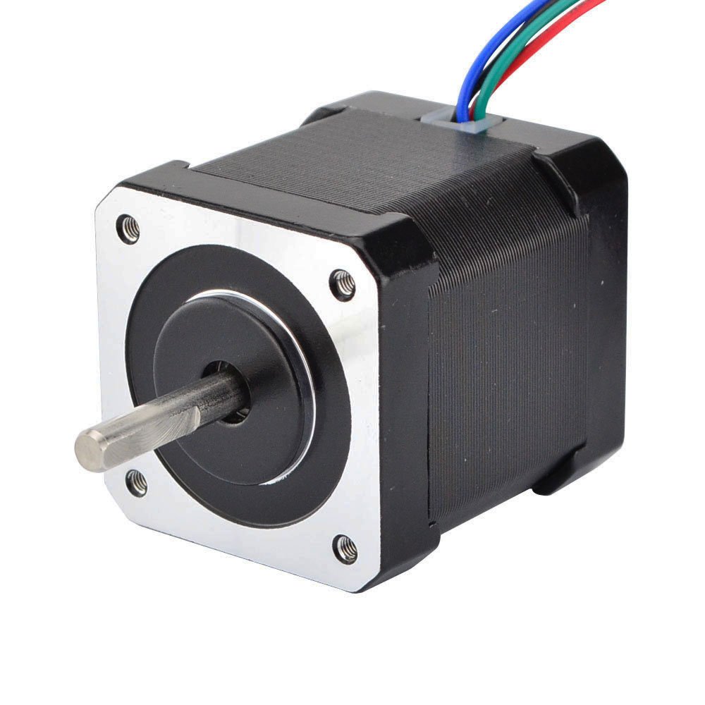
To understand the NEMA17's power and precision, it is necessary to understand it's internal mechanisms. As shown in the diagram below sourced from thefactorytheater.com, there are 3 main components to the motor, namely the rotor, stator and coils. "The rotor is the part that rotates. In most stepper motors, including NEMA 17s, the rotor is either a permanent magnet or a toothed iron core that interacts with the magnetic field generated by the stator. The stator surrounds the rotor and contains a series of electromagnetic coils. These coils are energized in a specific sequence, pulling or pushing on the rotor and causing it to move in small, discrete steps".

We'll also need a motor driver to use with the NEMA17, which will determine how and when the motor will rotate. The ideal and common type, which we also have available, is the DRV8825 shown here. It can control the speed and direction of the stepper motor with only 2 pins!! STEP controls the steps, DIR controls direction. The picture below and technical specifications can be found here.

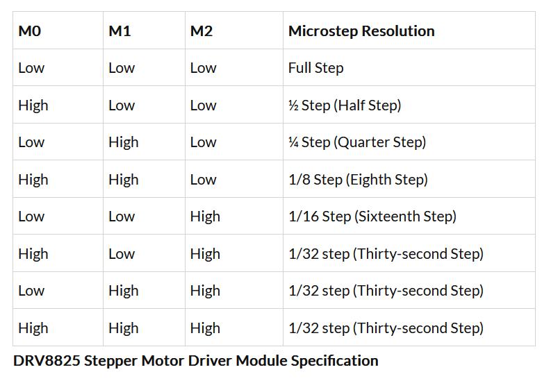
Furthermore, this driver can control even smaller steps, called microstepping. The following logic table details various the different microstep resolutions for given values on pins M0, M1, M2. Hence we see this driver provides a great degree of control over our stepper motor. However, that is not necessarily important to immediately implement as we just get started.
What is very important to see, understand is the pinout for the DRV8825, like this. Note RST is Reset, SLP is Sleep. M0,M1,M2 are for microstepping which we don't need in our first board. Rest should be self-explanatory.
STEP and DIR are the important pins controlling the speed and direction.
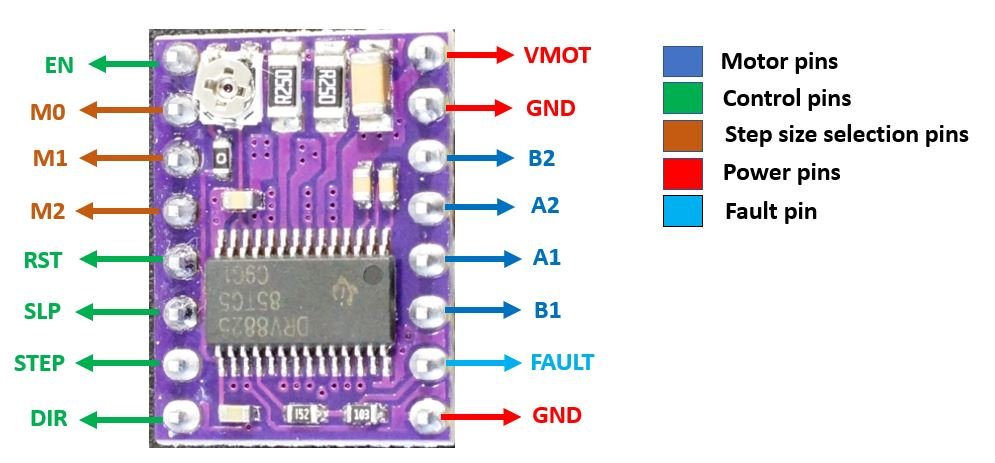
This tutorial was very helpful in my understanding. Thanks respect, and credits for pinout diagram.
NEMA17: part 2 - PCB
As usual, we start with a schematic in Kicad:

One new aspect for this board is a voltage regulator. On this board we must power the motor with 12V, but must also supply the microcontroller (ATtiny1614) with a smaller amount of 5V. To do this we have a voltage of 12V into the voltage regulator, and it converts to 5V.

Here is the schematic. It took a long time, going through multiple iterations. The size of the board is precisely 42 mm square as that is the size of the head of the motor.

With some difficulty I soldered the board, it looks a bit ugly but does it work?

We connected the board to 12V power supply. The LED lights up but doesn't blow up. This means that the voltage regulator works.

Here's a pinout of the board for reference:

NEMA17: part 3 - Programming
To program our NEMA motor we need a UPDI programmer such as Saheen has. However, we are traveling soon, so it seems a good time we're gonna make our own programmer and Saheen helps with sharing his design. Cut the board, gather the components:

Soldering took a long time, but now it's done. We tested on our previous week's output board the OLED. It works!

Now we're completely ready to program. Our setup looks like this:

NEMA Basic Program: This simple program turns the motor in one direction and then in the opposite direction forever. Initially there was a problem with the motor only turning in one direction, but upon further investigation this happened as I did a poor job soldering the direction pin, hence it was not connected and rotated in the one direction only.
// Define motor control pins
const int stepPin = 0; // Connect to STEP pin on driver
const int dirPin = 1; // Connect to DIRECTION pin on driver
const int stepsPerRevolution = 200; // Number of steps per full revolution for your motor
void setup() {
pinMode(stepPin, OUTPUT);
pinMode(dirPin, OUTPUT);
Serial.begin(921600);
}
void loop() { //Motor rotates forward then backward forever
// Rotate clockwise one full revolution
digitalWrite(dirPin, HIGH); // Set direction clockwise
Serial.println("Clockwise");
for (int i = 0; i < stepsPerRevolution; i++) {
digitalWrite(stepPin, HIGH);
delayMicroseconds(1000); // Adjust speed by changing delay time
digitalWrite(stepPin, LOW);
delayMicroseconds(1000);
}
delay(500); // Pause one half second
// Rotate counterclockwise one full revolution
digitalWrite(dirPin, LOW); // Set direction counterclockwise
Serial.println("Counter-Clockwise");
for (int i = 0; i < stepsPerRevolution; i++) {
digitalWrite(stepPin, HIGH);
delayMicroseconds(1000);
digitalWrite(stepPin, LOW);
delayMicroseconds(1000);
}
delay(500); // Pause one half second
}
NEMA Input Program: Saheen said it will be interesting and useful to control the motor movement from the Serial Monitor, so that's what this next program does. The user must just enter 'L' or 'R' in the serial monitor and then the motor does make one full rotation either Left or Right.
const int dirPin = 1; // DIR pin connected to digital pin 1
const int stepPin = 0; // STEP pin connected to digital pin 0
void setup() {
Serial.begin(57600); // Initialize serial communication at 9600 baud
pinMode(dirPin, OUTPUT); // Set direction pin as output
pinMode(stepPin, OUTPUT); // Set step pin as output
}
void loop() { //main loop which reads user input and if valid calls appropriate function
Serial.println("Enter R for Right or L for Left:");
while (Serial.available() == 0) { // Wait for user input
delay(10); // Small delay to avoid busy waiting
}
char input = Serial.read(); // Read the first character of the input
// Handle user input
if (input == 'R' || input == 'r') {
Serial.println("You chose Right!");
right();
} else if (input == 'L' || input == 'l') {
Serial.println("You chose Left!");
left();
} else if (input == '\n') {
} else {
Serial.println("Invalid input. Please enter R or L.");
}
delay(500); // Small delay to avoid repeated processing
}
void right() { //function to turn clockwise
digitalWrite(dirPin, HIGH); // Set direction to clockwise
Serial.println("Clockwise");
for (int i = 0; i < 200; i++) {
digitalWrite(stepPin, HIGH);
delayMicroseconds(1000); // 1 ms delay
digitalWrite(stepPin, LOW);
delayMicroseconds(1000); // 1 ms delay
}
}
void left() { //function to turn counter-clockwise
digitalWrite(dirPin, LOW); // Set direction to counter-clockwise
Serial.println("Counter-Clockwise");
for (int i = 0; i < 200; i++) {
digitalWrite(stepPin, HIGH);
delayMicroseconds(1000); // 1 ms delay
digitalWrite(stepPin, LOW);
delayMicroseconds(1000); // 1 ms delay
}
}
And here is video proof that the program works as required:
Files for Output Devices
SSD1306 OLED:
KiCad files for OLED board.Gerber files for OLED board.
1st program - basic
2nd program - lopaka
3rd program - MakerKootam
NEMA17 Motor:
KiCad files for NEMA17 BoardGerber files for NEMA17 Board
Basic Arduino program for NEMA
Input Arduino program for NEMA