Networking and communications
Objectives for Week 11
- Design, build, and connect wired or wireless node(s) with network or bus addresses and local input &/or output device(s)
- Send a message between two projects
Individual Assignment
Group Assignment:
Group Assignment
For this week’s group assignment, we established communication between two separate projects using the ESP-NOW protocol. The board equipped with a time-of-flight sensor transmitted a message over the network to the second board, which then responded by lighting up an LED.
Group assignment link.
Individual Assignment
This week, I worked on connecting three boards, where one board functioned as the controller, and the other two operated as responders. I utilized the I2C protocol to establish communication between them. The goal was to control both responder boards using the controller.
I2C
I2C (Inter-Integrated Circuit) is a communication protocol that allows multiple devices to communicate with each other using just two wires: one for data (SDA) and one for the clock signal (SCL). It is commonly used to connect microcontrollers, sensors, and other peripherals. In an I2C setup, one device acts as the controller, sending instructions, while other devices act as responders, receiving and responding to those instructions. This makes it efficient for connecting multiple components with minimal wiring.
Like UART communication, I2C only uses two wires to transmit data between devices:
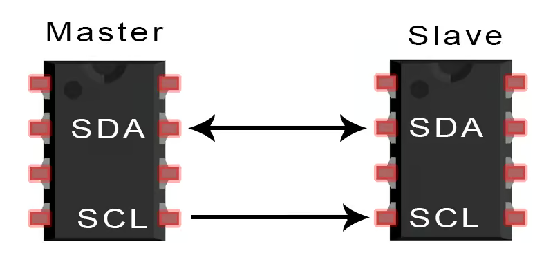
- SDA (Serial Data)- The line for the master and slave to send and receive data.
- SCL (Serial Clock)- The line that carries the clock signal.
To know more about I2C follow this link.
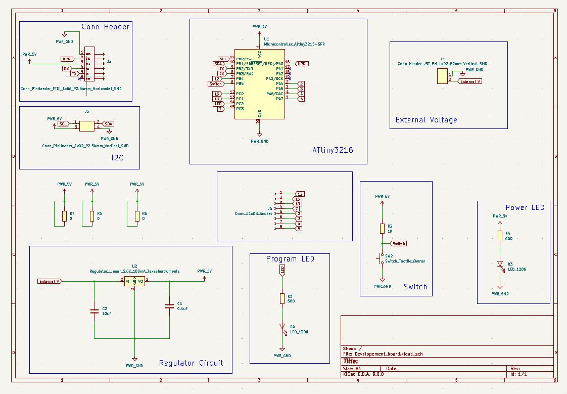
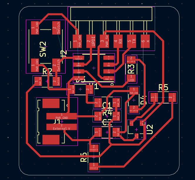
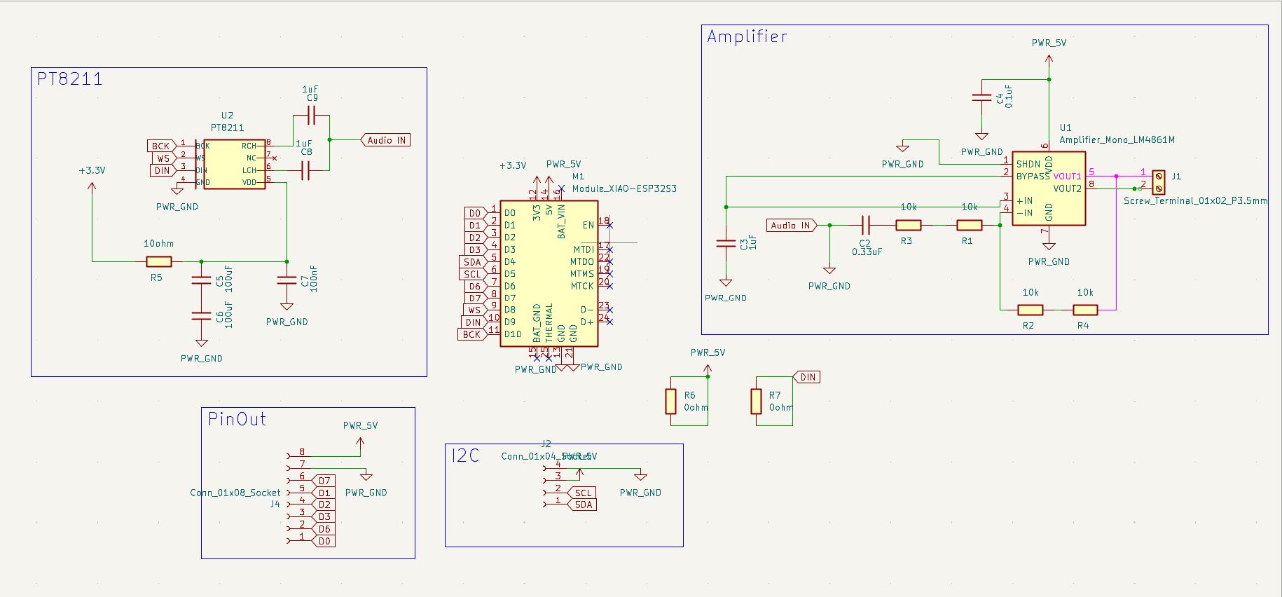
I made a developement board in the Electronics Design week using the ATtiny3216 and made a board using XiaoESP32S3 in the Output week. Both the boards have I2C connections as well.
|
|
|
|
Initially I decided to communicate these boards. If it works well I can design and produce new board.
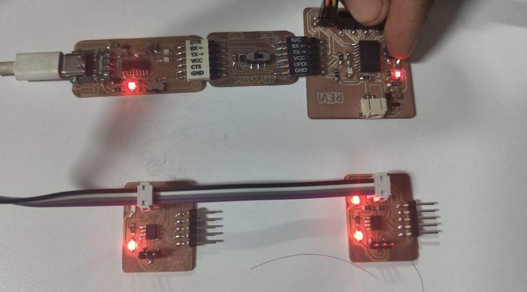
For understanding more about the communication I followed Midhun's documentation. And I got the basic idea of how communication between two boards works and I got the basic structure of the codes for the two boards as well. So I copied the code for the responder board and flashed it into the ATtiny3216 developement board I designed earlier using a programmer. Midhun had a button on his board and he switches the board using the button. I my master board I don't provided a button, So I just copied the code and using the helpof Chat GPT I wrote a code to toggle the LED state of the responder board with a delay of 1 second. This code was flashed into the Xiao ESP32S3 board. Using the jumper wires I connected both the boards and the LED of the responder board starts blinking. So the testing was sucessful so that I can make a new board and understand the codes as well.
Codes
Code for Master
#include <Wire.h>

    const int slaveAddress = 8; // I2C address
    int ledState = 0;  // Toggle state (0 = OFF, 1 = ON)

    void setup() {
      Wire.begin(); // Initialize I2C as master
    }

    void loop() {
      // Send command to toggle LED on the slave device
      Wire.beginTransmission(slaveAddress);
      Wire.write(ledState);
      Wire.endTransmission();

      // Toggle LED state for next loop
      ledState = !ledState;

      delay(1000); // Wait for 1 second
    }
|
Code for responder
#include <Wire.h>

    const int ledPin = 12;
    int ledState = LOW;

    void setup() {
      pinMode(ledPin, OUTPUT);
      digitalWrite(ledPin, ledState);

      Wire.begin(8);

      Wire.onReceive(receiveEvent);
    }

    void loop() {

      delay(100); // Small delay for stability
    }

    // Function to handle incoming data from the master
    void receiveEvent(int howMany) {
      while (Wire.available()) {
        int command = Wire.read();
        if (command == 0) {
          ledState = LOW;
        } else if (command == 1) {
          ledState = HIGH;
        }
        digitalWrite(ledPin, ledState);
      }
    }
|
ChatGPT promt:
Copied the first code(from midhun's documentation) This is a reference code I got. In my case I have a master code made with xiao esp32s3 and responder board made with attiny3116. Copy the second code. I flased this program into my responder board. Write a program for the master board to turn ON and OFF the LED of responder board with 1 second delay. As I dont have a button on my master board
Designing Nodes
Although the test with the XiaoESP32S3 was successful, there was no push button I placed in the board while I designed it. So I can't able to control the nodes manually or else I neede to use the serial monitor. Fortunately, the board I designed and made during the electronics design and electronics production weeks have the push button on it. So I chose it as my sender board. So I only needed to make the responder board this time.
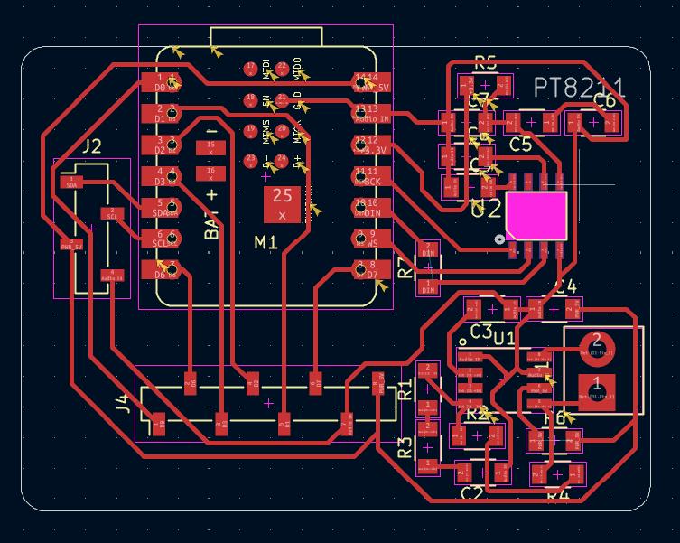
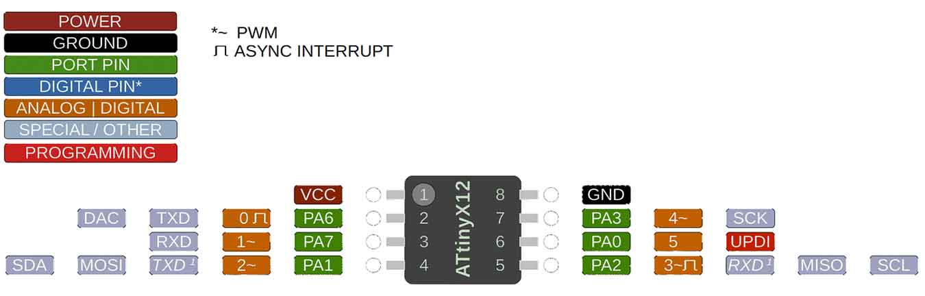
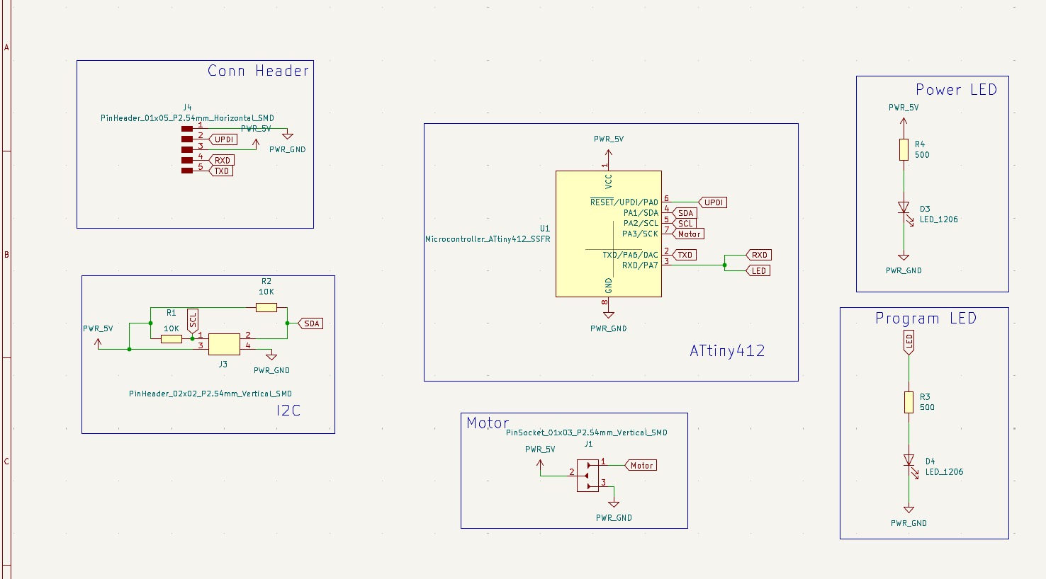
By following midhun's documentation I designed a board using ATtiny412 for controlling the servo motor. Also a programmable LED was also included in it. Click here for ATtiny412 datasheet.
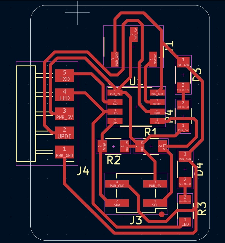
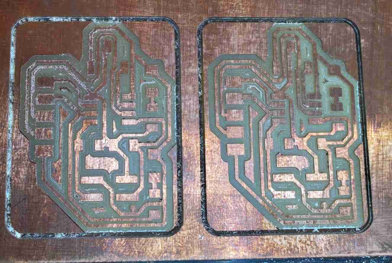
The schematics and the board design of the responder boards,
 |
 |
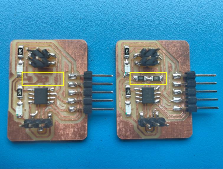
As I need to communicate the sender with more than I responder I milled 2 responder boards.
 |
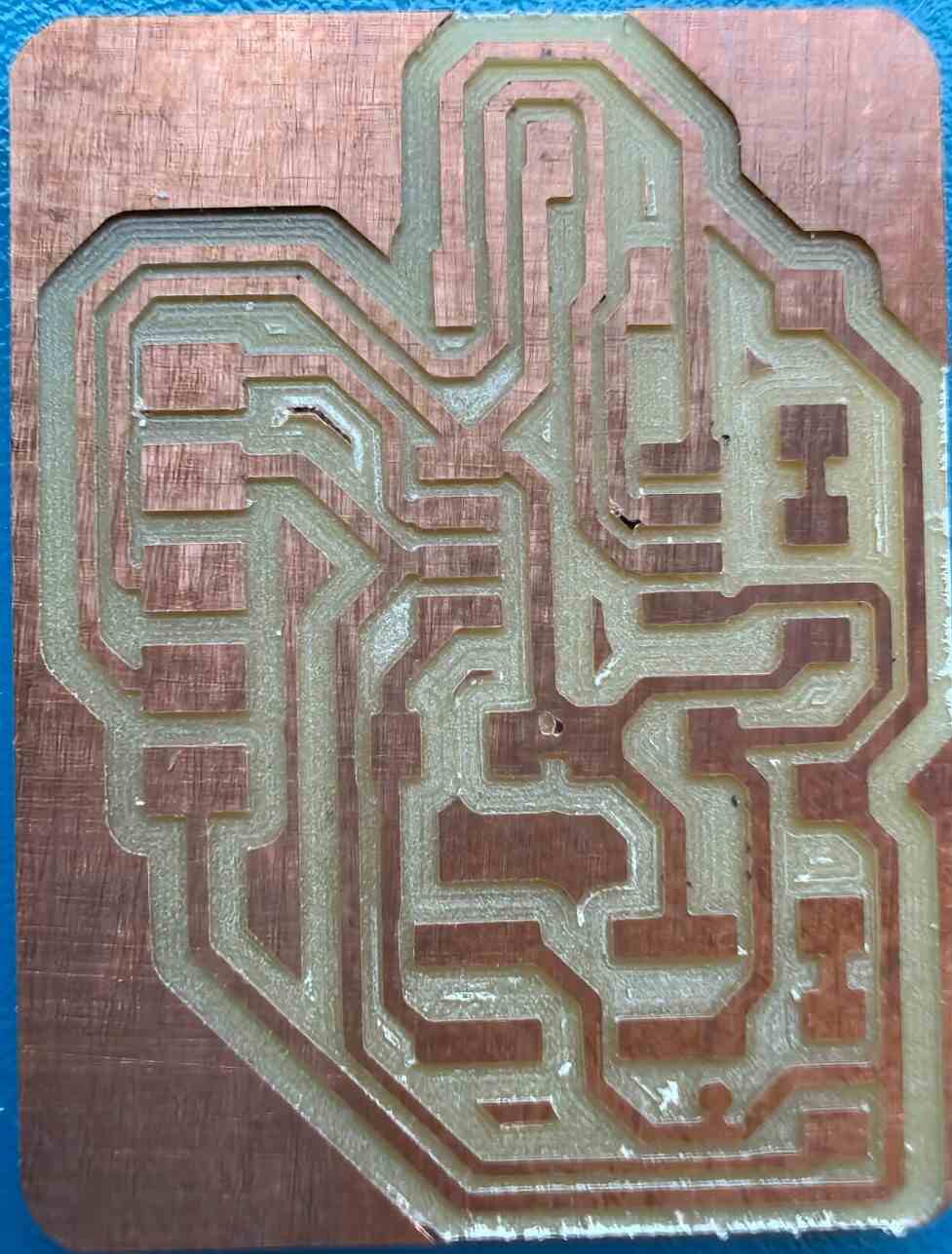 |
I took all the components from the inventory and soldered both the boards.
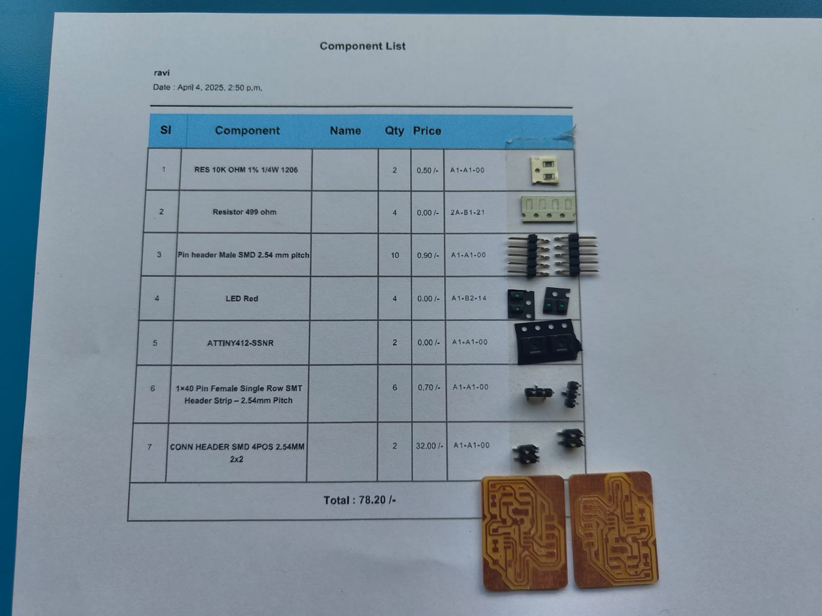
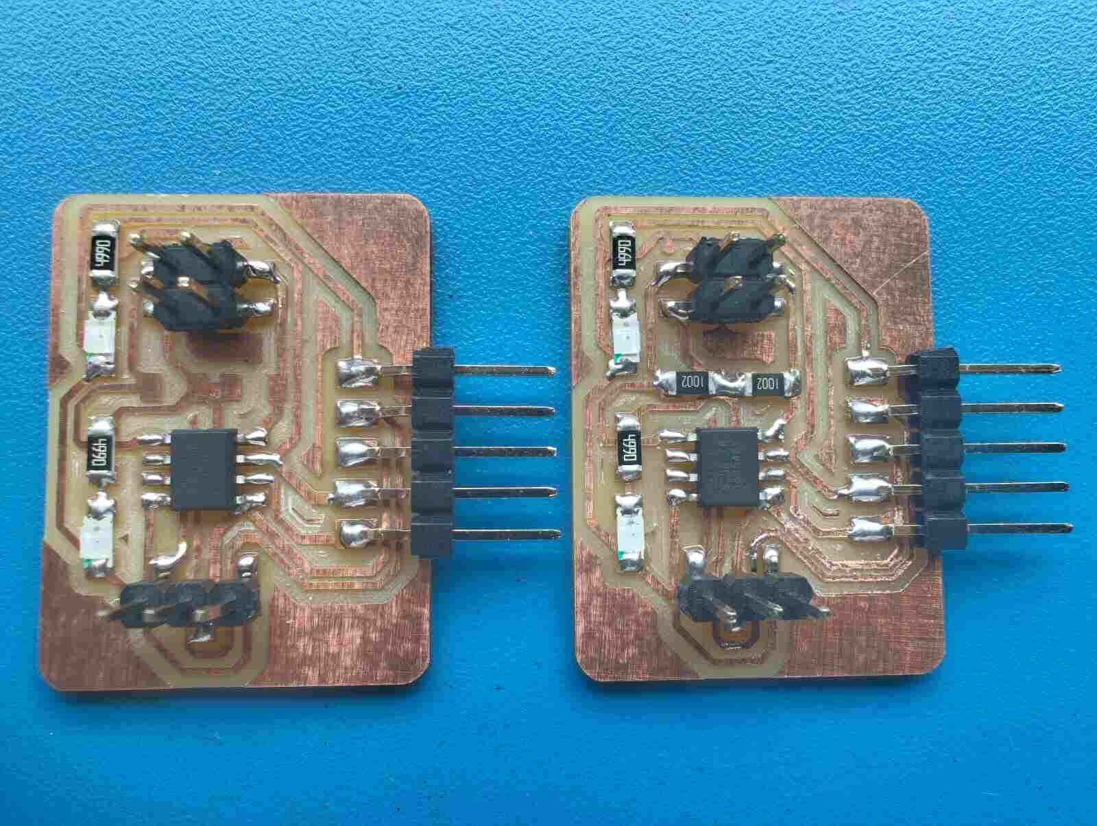
I I don't added the pull up resistors on the sender board while I designed it on the electronics design week, so I added pull up resistors of 10K to one of the responder boards.
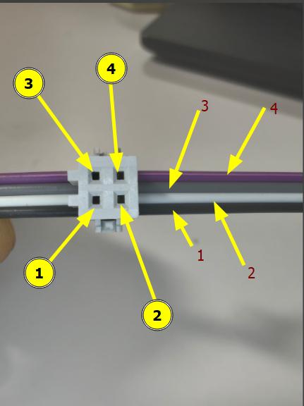
I made a JST 4 pin connector to connect my boards.
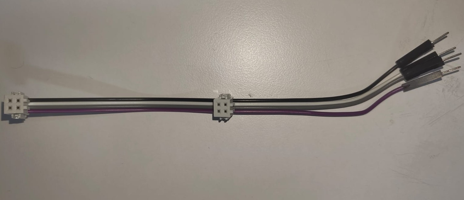
The wire connections were like this,
Block Diagram
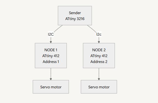
Then I tried to connect and impliment communication between these boards. I tried to made a program when I press the button on the sender board the LED on one responder board turn ON and in next button press the current board's LED turn OFF and the LED on the other board turns ON and the cycle repeats whenever I press the button.
Programming
Sender Program
  #include <Wire.h> // Include the I2C library to use I2C communication

    #define BUTTON_PIN  4   // The pin where the button is connected
    #define SLAVE_1_ADDR 8  // I2C address of Slave 1
    #define SLAVE_2_ADDR 9  // I2C address of Slave 2

    int toggle = 0;  // This will help switch between slave 1 and slave 2

    void setup() {
      pinMode(BUTTON_PIN, INPUT_PULLUP);  // Set button pin to input with a pull-up resistor
      Wire.begin();  // Start I2C communication
    }

    void loop() {
      if (digitalRead(BUTTON_PIN) == LOW) {  // Check if the button is pressed
        delay(200);  // Wait for 200ms to debounce the button (ignore multiple presses)

        // Send a signal to turn the LED on for the selected slave
        Wire.beginTransmission(toggle == 0 ? SLAVE_1_ADDR : SLAVE_2_ADDR);
        Wire.write(1);  // Send '1' to turn LED ON
        Wire.endTransmission();  // End I2C transmission

        // Send a signal to turn the LED off for the other slave
        Wire.beginTransmission(toggle == 0 ? SLAVE_2_ADDR : SLAVE_1_ADDR);
        Wire.write(0);  // Send '0' to turn LED OFF
        Wire.endTransmission();  // End I2C transmission

        toggle = (toggle == 0) ? 1 : 0;  // Toggle between 0 and 1 for the next button press
      }
    }
Explanation
- Included Wire library
- Define Constants
- Variable Declaration
- Setup Function
- Main Loop
#include <Wire.h>Included the Wire.h library for I2C Communication
#define BUTTON_PIN  4

  #define SLAVE_1_ADDR 8

  #define SLAVE_2_ADDR 9
Defined Pin number 4 as LED pin Responder board 1 as Address 8 and responder 2 as Address 9
int toggle = 0;
Toggle between the responder
    void setup() {
      pinMode(BUTTON_PIN, INPUT_PULLUP);
      Wire.begin();
    }
Here the button pin set as input with internal pullup. Means the button will remains always High. Wire begin is to start the I2C communication.
  void loop() {

    if (digitalRead(BUTTON_PIN) == LOW) {

      delay(200);


    Wire.beginTransmission(toggle == 0 ? SLAVE_1_ADDR : SLAVE_2_ADDR);

    Wire.write(1);

    Wire.endTransmission();


    Wire.beginTransmission(toggle == 0 ? SLAVE_2_ADDR : SLAVE_1_ADDR);

    Wire.write(0);

    Wire.endTransmission();


    toggle = (toggle == 0) ? 1 : 0;

   }

}
The initial set is for button press detection and a delay of 200 milli seconds given for debouncing.
The next two sections is to turn ON and OFF LED's of the 2 boards.
Responder Program
    #include <Wire.h>  // Include the I2C library to use I2C communication

      #define LED_PIN 1  // The pin where the LED is connected

      void setup() {
        pinMode(LED_PIN, OUTPUT);  // Set the LED pin as output
        Wire.begin(8);  // Start I2C communication as a slave with address 8 (use 9 for Slave 2)
        Wire.onReceive(receiveData);  // Call receiveData when data is received from the master
      }

      void loop() {
        // Nothing happens here, as the slave is waiting for data from the master
      }

      // This function runs when the slave receives data
      void receiveData(int len) {
        if (Wire.read() == 1) {  // If the master sends '1', turn the LED ON
          digitalWrite(LED_PIN, HIGH);  // Turn the LED on
        } else {
          digitalWrite(LED_PIN, LOW);  // If the master sends '0', turn the LED OFF
        }
      }
The communication worked as I expected,
  ChatGPT Promt: I have a sender and 2 responder boards. The Sender board have ATTiny 3216 and  and the responder boards have AtTiny412 on them.
 A button is connected to the pin 4 of ATTiny3216 and a LED is connected to Pin 1 of ATtiny412. So When I click the button LED on one board needed
 to be turned ON while the other wil bw off and on next click The LED on the other board needed to be turned ON with the other off and should be repeated.
Next I tried to control the servomotors using the nodes. This time I noticed that I can't able to program one of my responder board. I tried multiple times and failed. But the other one was programming correctly.
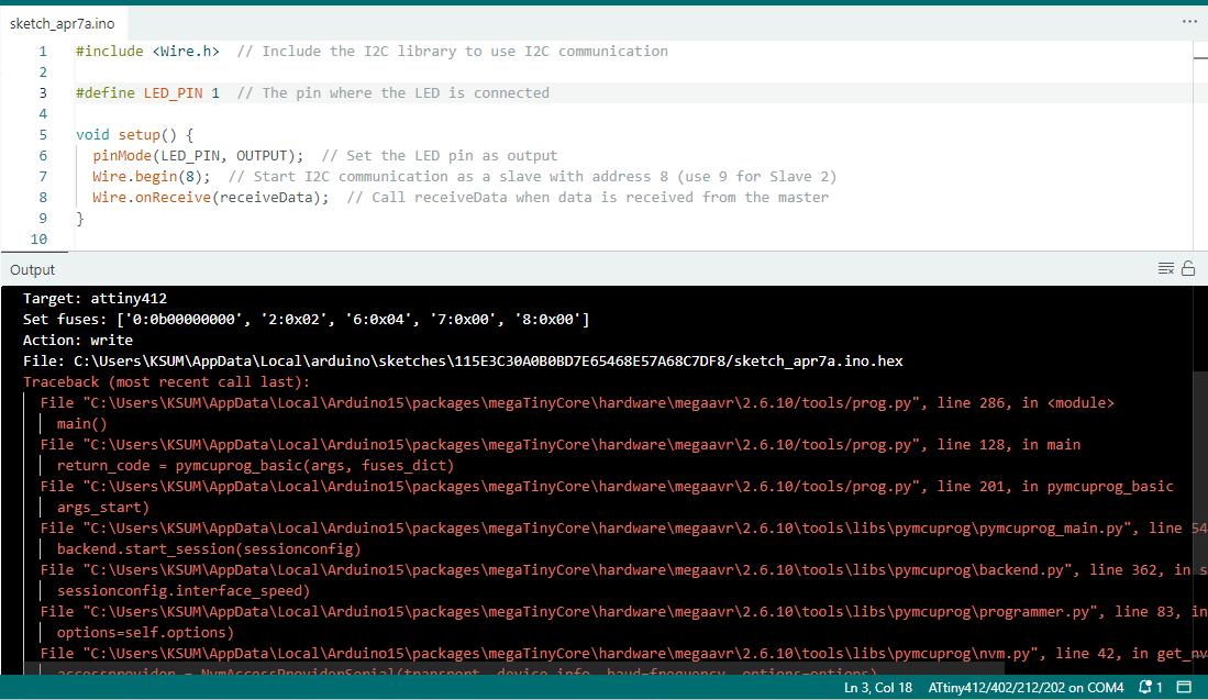
|
|
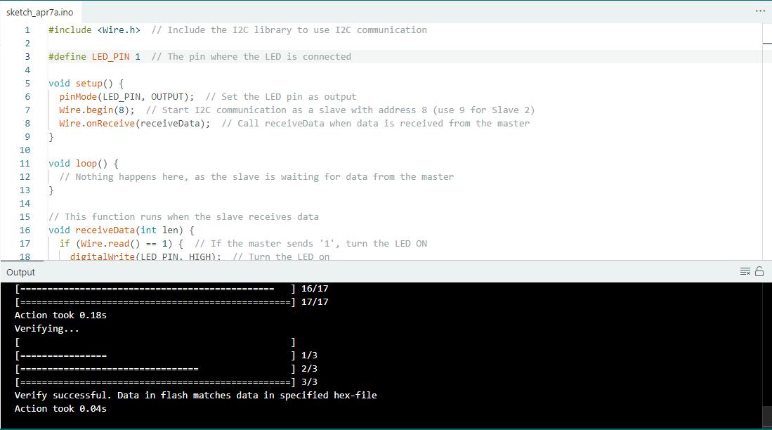
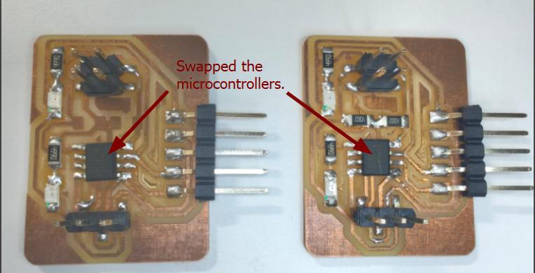
The board in which I placed the pullup resistors for I2C was not programming. So I swaped the ATtiny412 microcontrollers of both the boards to check whether the issue with the microcontroller. This time the board with pullup resistors was programmed and the other one fails to program. So I identified it was the issue with my microcontroller. Unfortunately I couldn't able to find what was the reason for the microcontroller to fail.
So I replaced the ATtiny412 and the issue was solved.
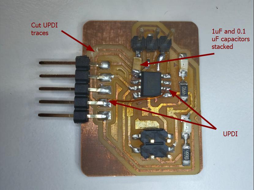
So it works fine untill I connected the sevo. After connecting the servo, the time servo starts running the chip fails again. I don't have any idea what is happening. So I consulted our Instructor Saheen and he advices me to replace the chip and try again. This time also the chip fails. He helped me with debugging and he told me that while routing the UPDI neede to gave the first priority and connected with the shortest path possible. I tracks of the UPDI I routed was too long. Also told me to add a 1uF and 0.1uF capacitor between the power pin of the motor and the ATtiny412. Cut the UPDI tracks and wired it as well.
The reason for the chip to fail because when the motor works sudden voltage spikes get into the microcontroller. To avoid that the capacitors were added.
Adding the capacitor also doen't solved the issue. Fortunately I added a programmable LED on both the boards so that I can able to complete the assignment by toggling thw state of the LEDs on both the boards by my main board.
Heroshot
Conclusion
In conclusion, this week’s exploration of networking and communication proved to be both challenging and rewarding. By utilizing the ATtiny3216 board as the sender and the ATtiny412 boards as responders, I successfully established communication between the boards. Despite facing some initial issues, I was able to troubleshoot and resolve them, leading to a smooth and effective communication setup. This experience has greatly enhanced my understanding of networking concepts and the practical implementation of communication between microcontrollers.