Output Devices
Objectives for Week 10
- Attach an output device to the microcontroller board I designed and program it to perform a task.
- Measure the power consumption of an output device.
Individual Assignment
Group Assignment:
Group Assignment
As part of the group assignment, we calculated the power consumption of Sg90 servo using a bench power supply. The SG90 servo draws a maximum power of 1.5W
Group assignment link.
Individual Assignment
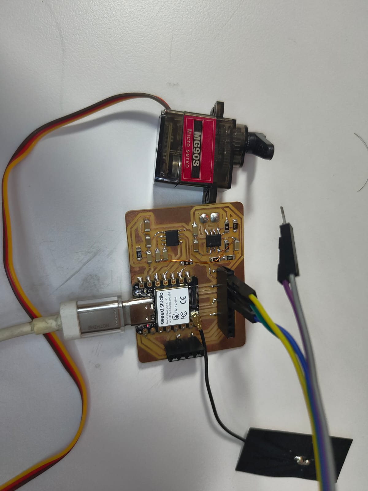
My final project is a talking toy. Its head can be tilted at an angle as well. So this week I took Speaker and servo motor as my output devices.
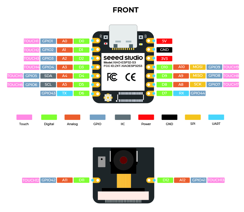
I still a beginner in programming, I need to spend more time on programming this week. So I choose Xiao ESP32S3 as my microcontroller for this week.
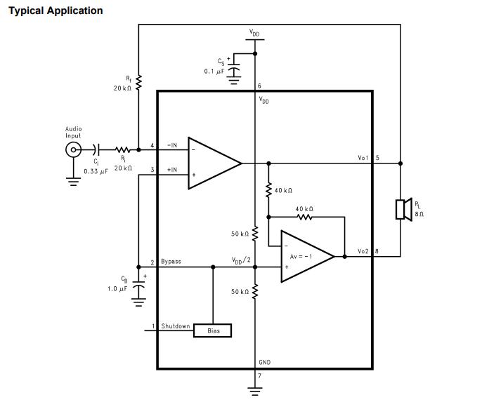
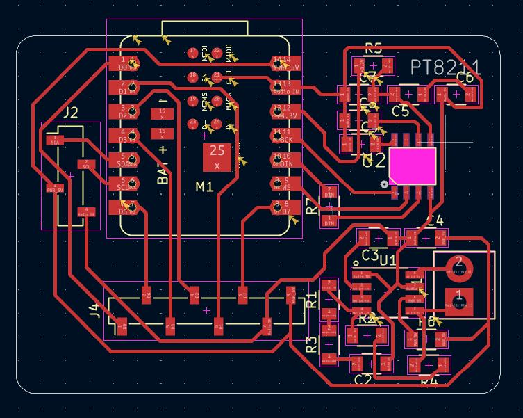
To control the speaker an amplifier needed to be included in the circuit. We have LM4861M amplifier in our lab. Refering the datasheet I made the basic circuit for the amplifier. As we don't have the electrolytic capacitors in our lab I chose the ceramic capacitor for the circuit.
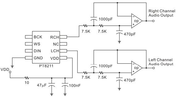
For audio control the I2S protocol is necessary and the microcontrol should have the I2S protocol. Unfortunately I haven't checked the I2S capability of the microcontroller and the XiaoESP32S3 doesn't offer I2S support. So I need to use Digital to analog converter IC PT8211 in the circuit to control the speaker. I haven't used the Lowpass Filter but connected both the RCH and LCH using a 0.1uF capacitor.
Using the header pin sockets I pulled out the I2C pins so that I can Connect any I2c devices to my board. All other pins were pulled out using the header pin sockets so that I can connect the servo motor.
After collecting all these informations, I designed the board in KiCAD.
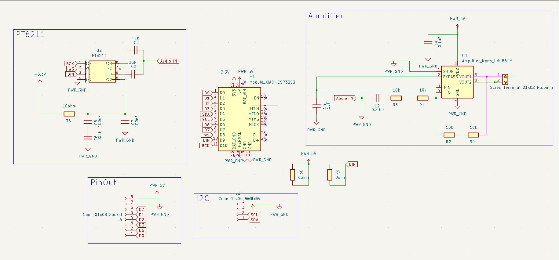
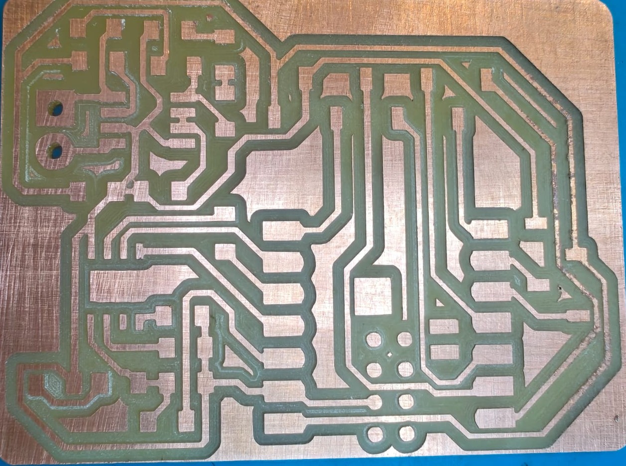
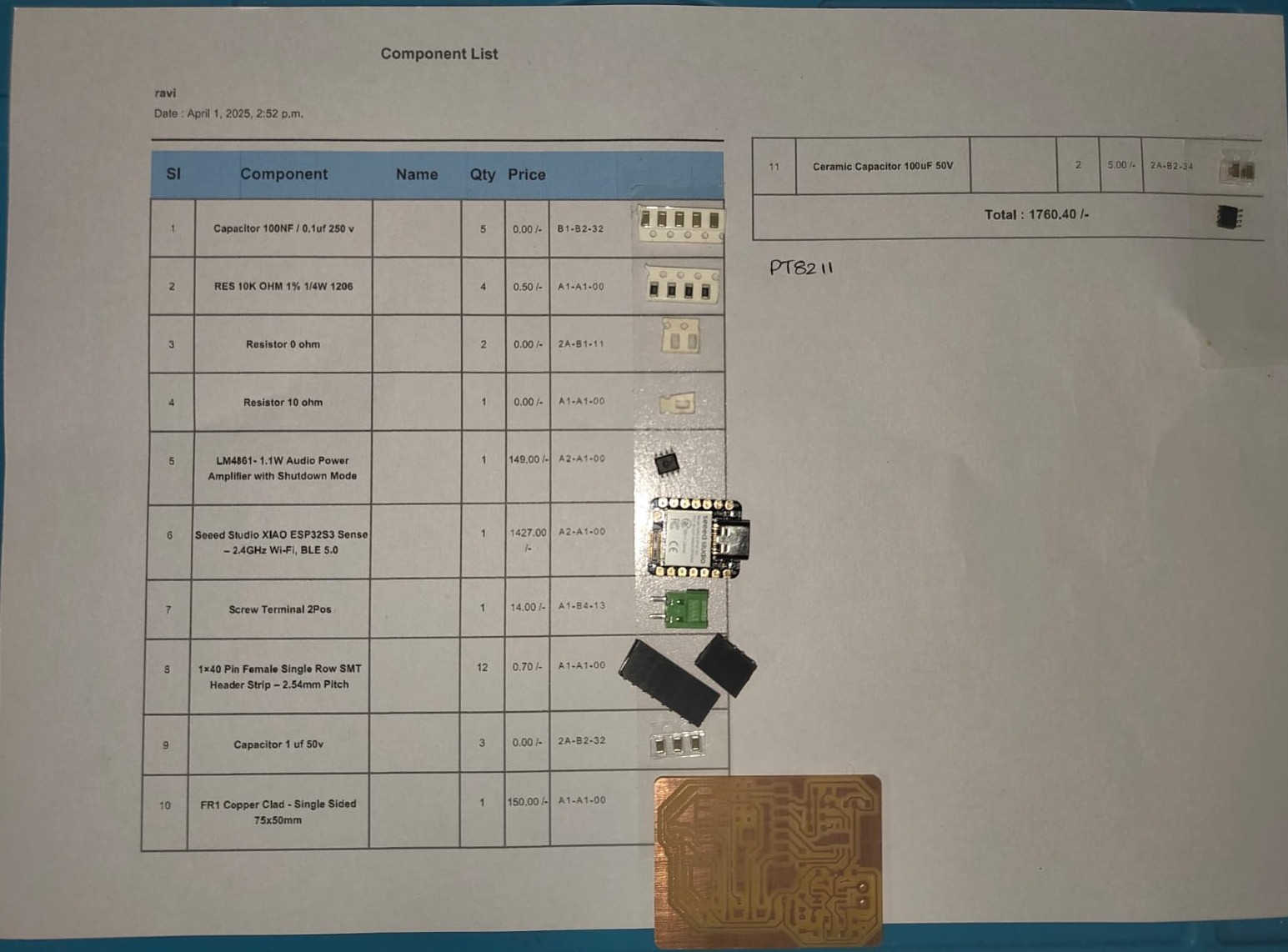
Then I milled it and took all the necessary components from the inventory and soldered it.
|
|
I tested it with the blink program available in the arduino IDE and it works fine as expected.
Servo Motor
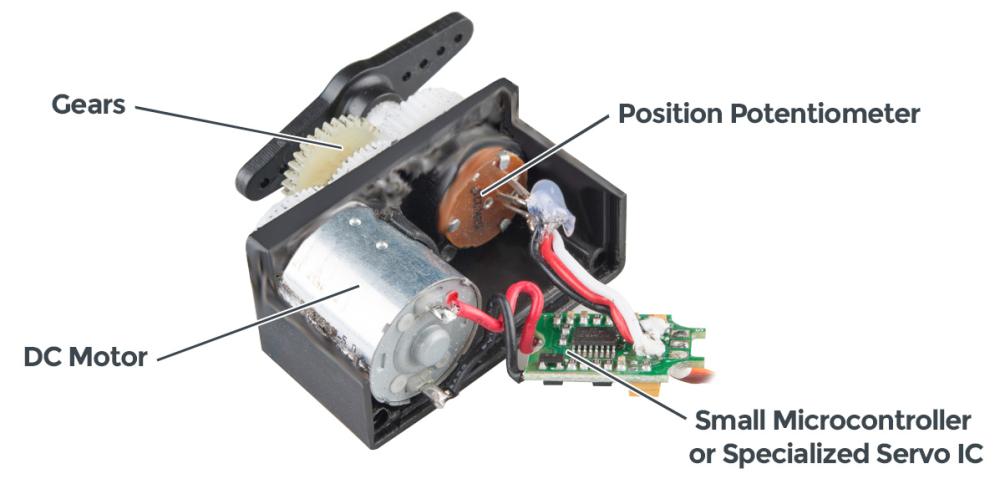
A servo motor is a highly specialized motor designed for precise control of rotary or linear motion. It’s a rotational or translational motor that employs a feedback mechanism to ensure exact positioning, typically using a control signal that dictates the motor’s movement to a desired position. This mechanism allows for precise control of various components, making servo motors crucial in applications where precise positioning and smooth motion are required.
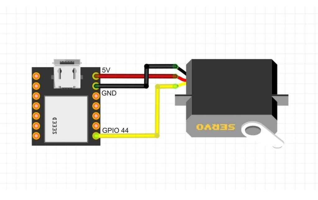
I followed Autodesk Instructables to setup the servomotor with the Xiao ESP32S3. The connections were simple as you need a power pin, A GND pin and a GPIO pin capable of PWM output.
After all the wiring, I refered my classmate Noel's documentation for programming.
The program works well and the output is shown below,
  #include <ESP32Servo.h>
    Servo myServo;

    #define sPin 44
    #define PULSEMIN 500
    #define PULSEMAX 2500
    int pos = 180;

    void setup(){
        Serial.begin(9600);
        pinMode (sPin, OUTPUT);
        ESP32PWM::allocateTimer(0);
        myServo.attach (sPin, PULSEMIN, PULSEMAX);
    }

    void loop (){
        // //To caibrate
        // myServo.write(pos);
        // Serial.print("Servo position: ")
        // Serial.println(pos);

        // To sweep
        for (pos=0; pos<=180; pos+=1){
        myServo.write(pos);
        Serial.print("Servo position: ");
        Serial.println(pos);
        delay(15);

        }
        delay(1000); //Stops for a second after reaching 180 degree

        for (pos=180; pos>=0; pos-=1) {
        myServo.write(pos);
        Serial.print("Servo position: ");
        Serial.println(pos);
        delay(15);
        }
        delay(1000); //Stops for a second after reaching 0 degree
    }
After this I tried to make a program when I enter a value between 0 to 180 on the serial monitor then the servo moves to that position.
Code
#include <ESP32Servo.h>
Servo myServo;
void setup() {
Serial.begin(115200); // Serial monitor Baud rate
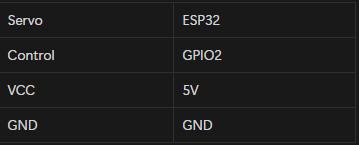
myServo.attach(2); // Servo connected to GPIO2
myServo.write(0); // Move to its 0 position
}
void loop() {
if (Serial.available()) { // Check anything typed
int angle = Serial.parseInt(); // Read the number typed
if (angle >= 0 && angle <= 180) {
myServo.write(angle); // Move to that angle
}
}
}
Code Explanation
This was a code written to sent and accept value through a serial monitor.
- #include <ESP32Servo.h>- Esp32 library for servo.
- Servo myServo; - Servo is a clas from servo.h library which will control the servo motors.
- void setup() {
Serial.begin(115200); // Serial monitor Baud rate
myServo.attach(2); // Servo connected to GPIO2
myServo.write(0); // Move to its 0 position
}
It will begin the serial monitor with 115200 baud rate, declare servo is attached to GPIO2, and moves the servo to its 0 position.
- void loop() {
if (Serial.available()) { // Check anything typed
int angle = Serial.parseInt(); // Read the number typed
if (angle >= 0 && angle <= 180) {
myServo.write(angle); // Move to that angle
}
- Check the value from the serial if the value is between 0 and 180 it will rotate to that direction.
Speaker
Our instructor Saheen gave me an 8ohm 5W speaker. Initially I tested it with the function generator to test the speaker. Selected the square wave and given the amplitude as 5 and frequancy as 2.8 initially. Then adjusted the value of frequancy so that the speaker produces the sound.
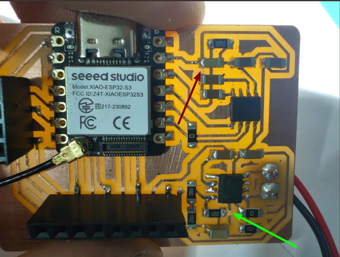
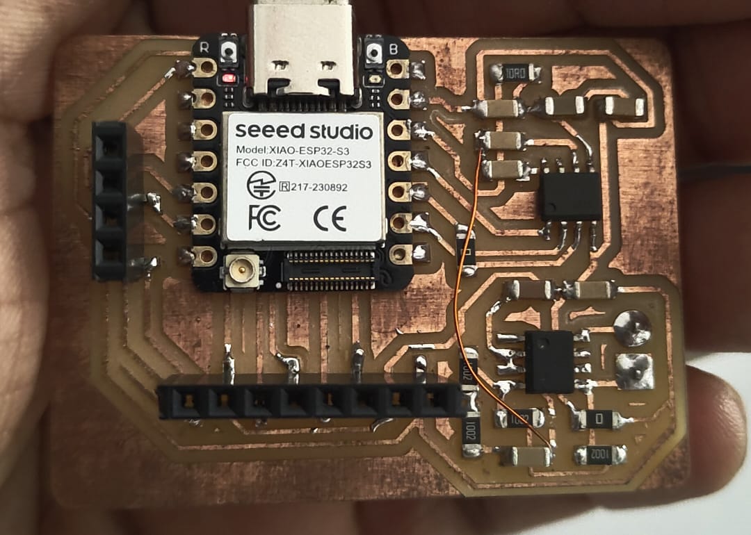
Then I connected the speaker to the board I designed and tried a basic code to beep in different frequencies. Unfortunately it doesn't work. I tried so many times and failed every time. I consulted my instructor Saheen and he inspected the board and told me that the the Audio In pin of the amplifier pin was grounded so that the signals produced from the microcontroller was directly grounded and hence the audio is not hearing.
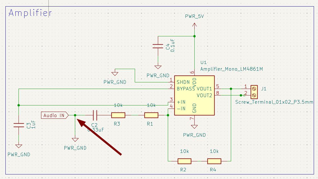
He adviced me to cut the traces marked in the below image and join it using a wire and I did it.
 |
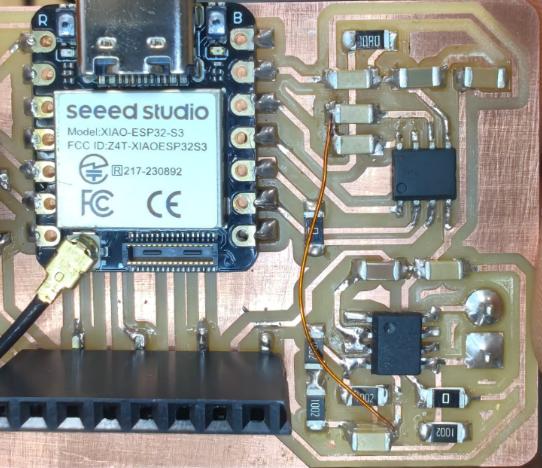 |
Unfortunately this modifications also doesn't helps with working of the speaker. I tried with different codes and the value was printing on the serial monitor but there was no output from the speaker.
While designing I just included the header pins for connecting the OLED display. So after trying to wrok with the speaker failed I just switched to print something in OLED display.
I took 0.96inch OLED display for that.
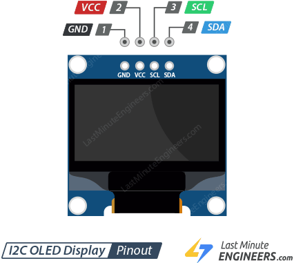
I connected the display to the board I made and I refered Random Nerd Tutorials for understanding the OLED display.
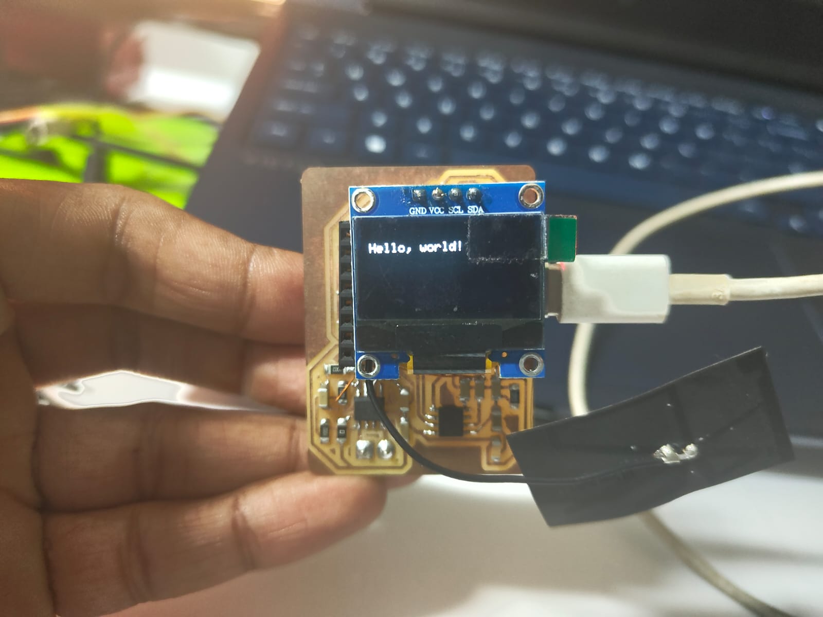
I tried to print Hello, world! on the display.
Code
#include  <Wire.h>
#include  <Adafruit_GFX.h>
#include  <Adafruit_SSD1306.h>

#define SCREEN_WIDTH 128 // OLED display width, in pixels
#define SCREEN_HEIGHT 64 // OLED display height, in pixels

// Declaration for an SSD1306 display connected to I2C (SDA, SCL pins)
Adafruit_SSD1306 display(SCREEN_WIDTH, SCREEN_HEIGHT, &Wire, -1);

void setup() {
  Serial.begin(115200);

  if(!display.begin(SSD1306_SWITCHCAPVCC, 0x3C)) { // Address 0x3D for 128x64
    Serial.println(F("SSD1306 allocation failed"));
    for(;;);
  }
  delay(2000);
  display.clearDisplay();

  display.setTextSize(1);
  display.setTextColor(WHITE);
  display.setCursor(0, 10);
  // Display static text
  display.println("Hello, world!");
  display.display();
}

void loop() {

}
Heroshot
Heroshot
 |
|
Conclusion
This week, I explored various output devices and designed a custom board that could interface with both a speaker and a servo motor. While I was successful in controlling the servo motor, the speaker did not function as expected. Despite this setback, the process gave me a deeper understanding of how speaker circuits work, and I’m confident that I will be able to troubleshoot and make it work in the future. To continue experimenting, I tested an OLED display. I was able to get it working and successfully printed "Hello World" on the screen.