PCB Design and Fabrication
Mother Board
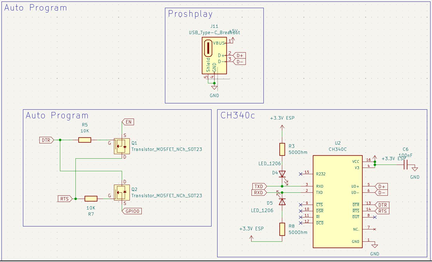
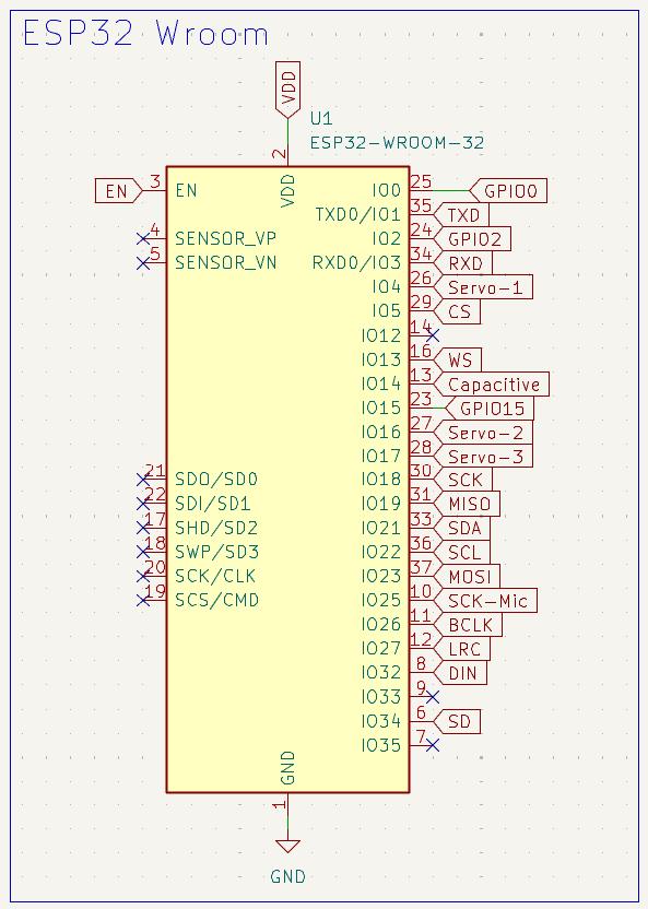
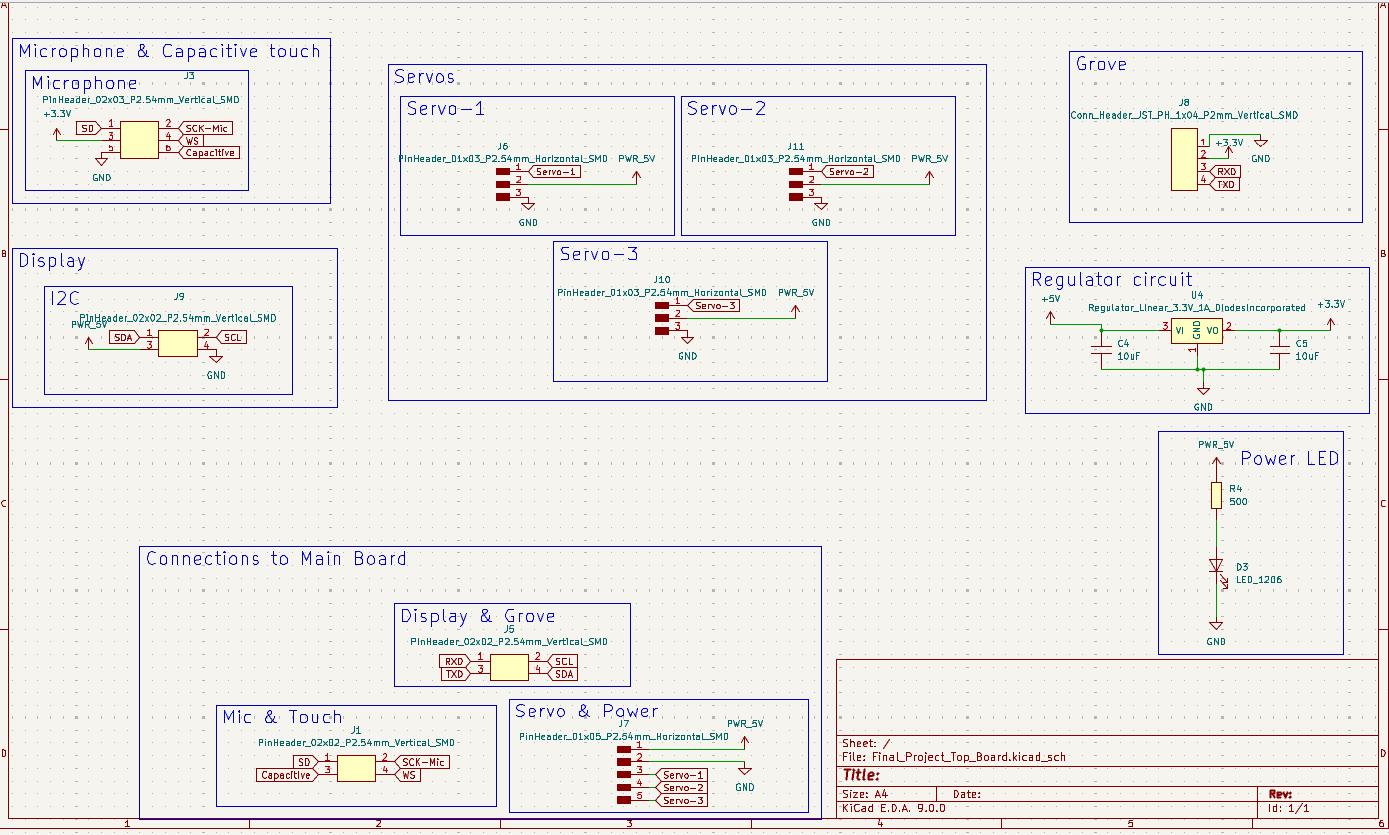
Schematics
The PCB was designed on KiCAD. The project have 2 PCBs with I contains the microcontroller and all the other modules and the other only have connectors to reduce the wires coming to the main boars which is placed below the toy.
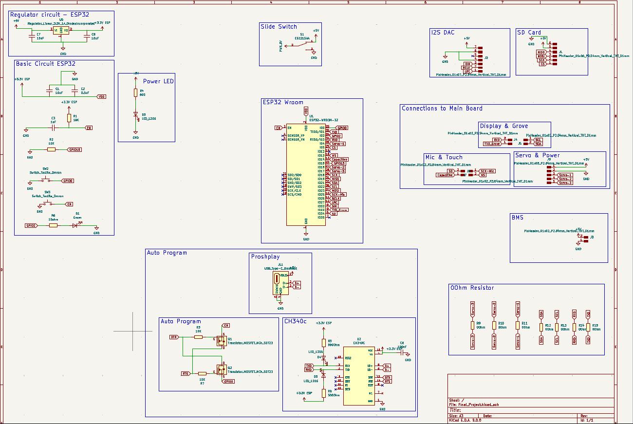
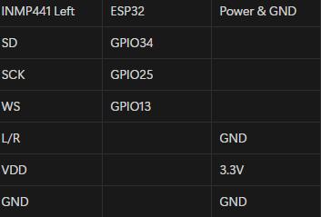
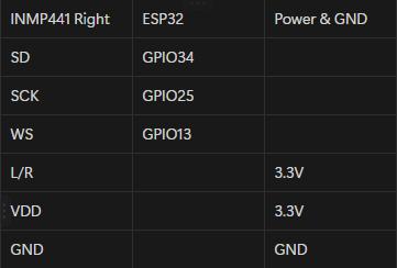
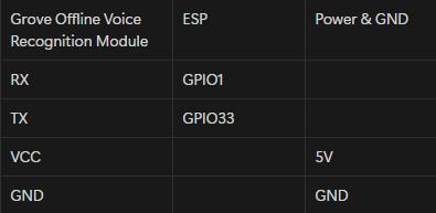
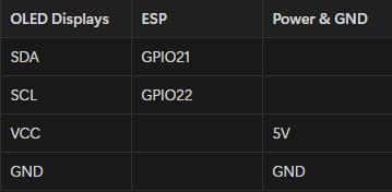
The connections were listed below,
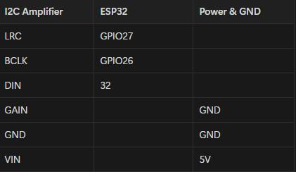
- MAX98357 I2S 3W Class D Amplifier Interface Audio Decoder Module Filterless Board
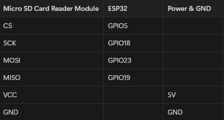
- Micro SD Card reader module
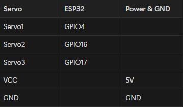
- Servo
- INMP441 MEMS Microphone
- Grove Offline Voice Recognition Module
- OLED Display
- The Capacitive touch was connected to GPIO14
 |
 |
I integrated the CH340C on to the board so that no external programmer was needed. Also autoprogrammer also included.
 PCB Design
Due to the size constrain I designed double sided board.
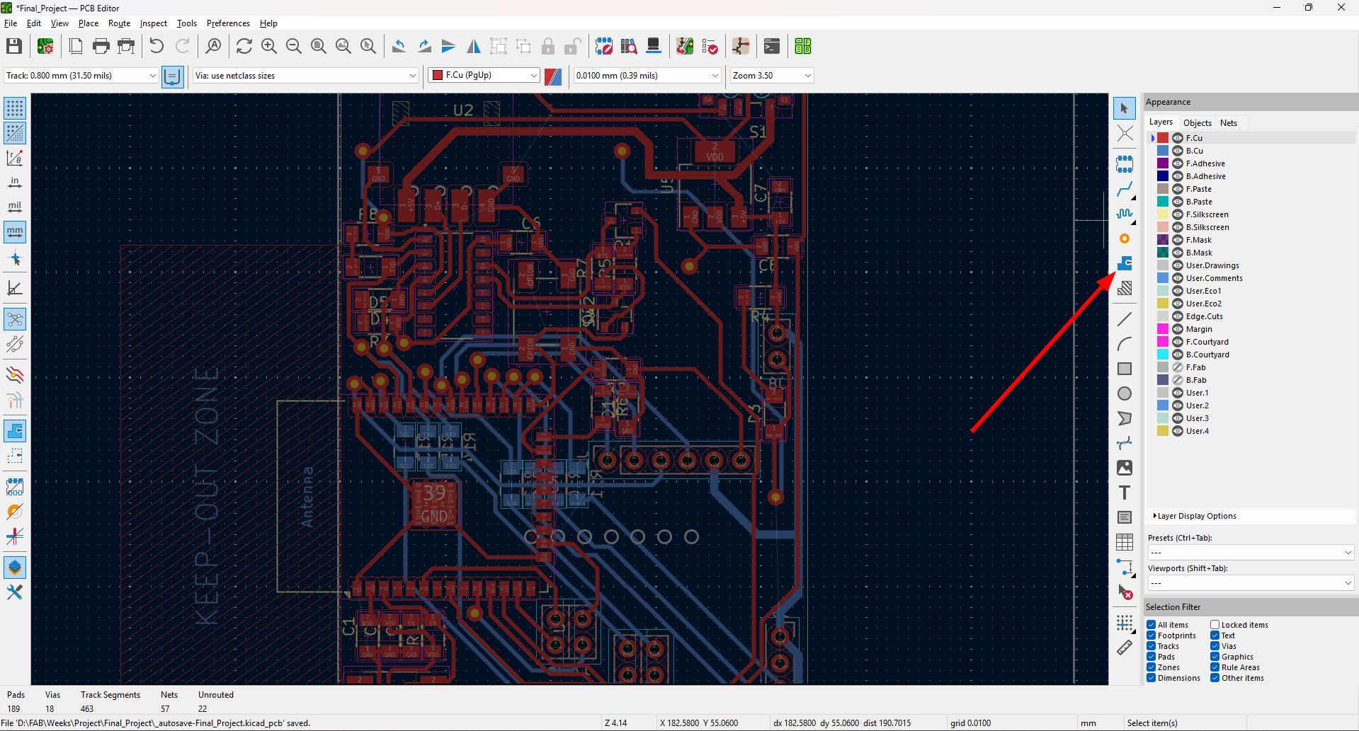
I used the common ground for easiness. The steps for common ground,
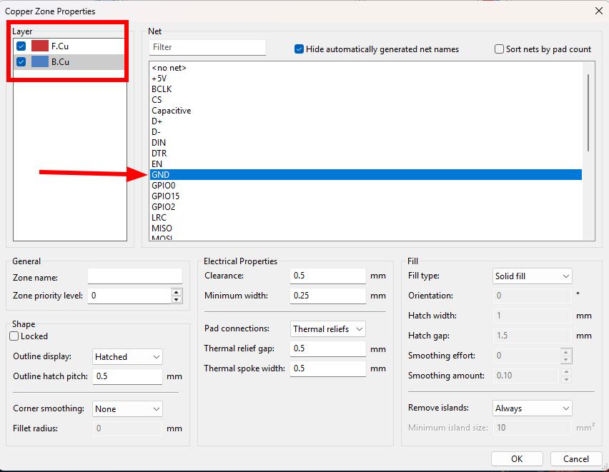
- Select the Draw filled zones options marked in the image
- Select the F.Cu and B.Cu and select GND.
- Draw the areas to fill the GND.
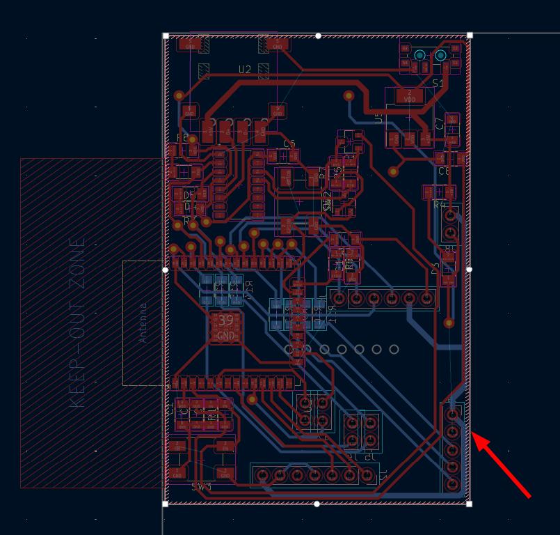
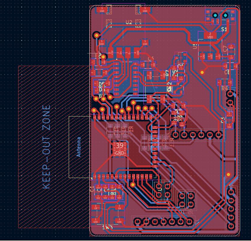
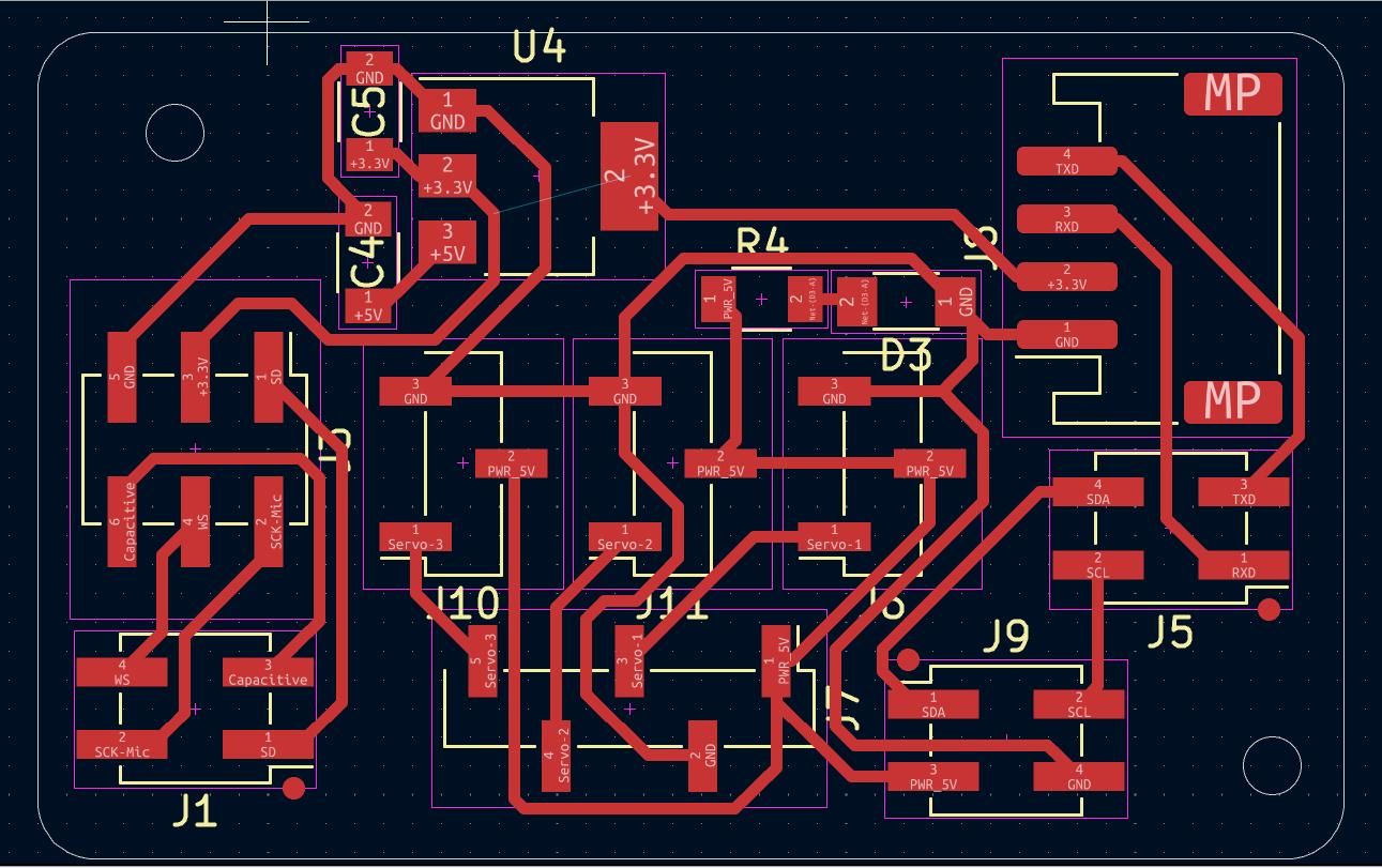
The final PCB looks like this,
Exported the gerber file and made the board. To know more Click here.
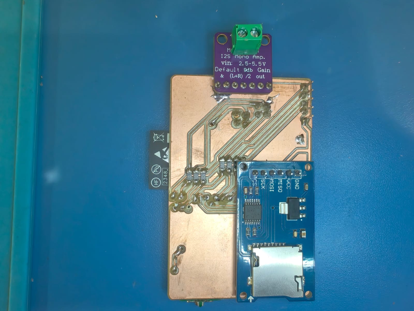
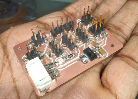
Fabricated the board and the final board looks like this,
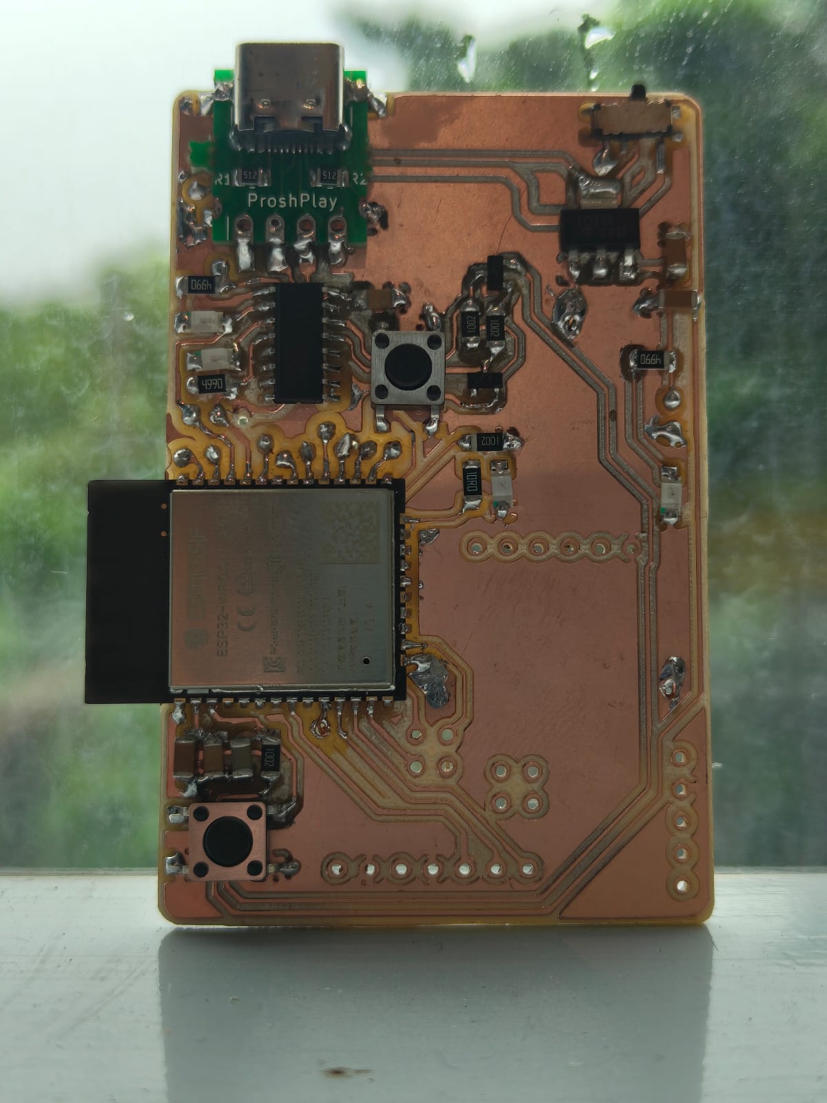 |
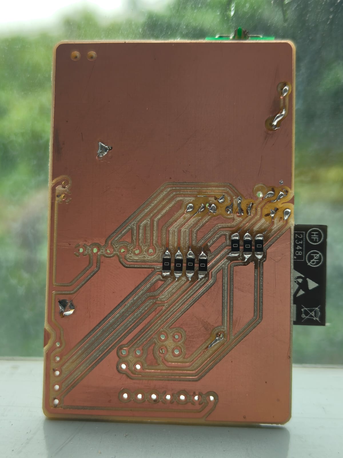 |
Unfortunately while designing I wrongly connected the RX and TX and which cause error while programming. Our instructor Saheen just cuts those traces and soldered it correctly and the issue was resolved.
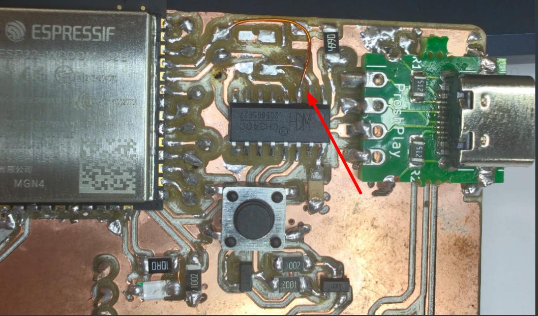
Note: The CH340C and Proshplay Type C breakout board Symbol and Footprint was not available in the fab library and can be found at the bottom of this documentation.
Secondary Board
The board 2 is designed for all the connections so that the power lines going to the base can be reduced. Only one 5V and GND is coming up and is splits in board 2 and also converted into3.3V also.
Exported the gerber files and converted into PNG in gerber2PNG and milled and soldered it.
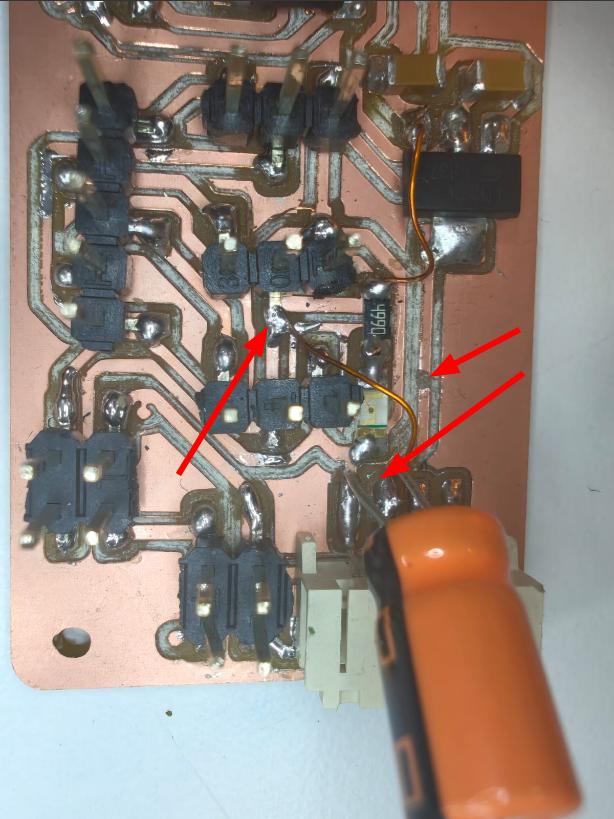
After soldering I noticed that the 5V is not completly routed and I connected it using wire.
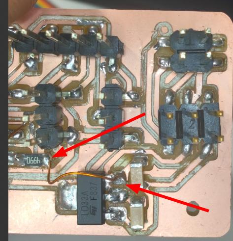
While testing it was noted that the grove module was not getting enough power to work and it was connected to the 3.3v. Then I cut the traces and connected it to the 5V supply and added a capacitor to it.
All the testing process were mentioned on the testing page.