Week 11
Networking and Communications
For the individual assignment, you will need to design, build, and connect either a wired or wireless node (or multiple nodes) with assigned network or bus addresses. Each node should include local input and/or output devices to demonstrate functionality.For the group assignment, you will collaborate to send a message between two separate projects, ensuring communication is established successfully. This task will help you explore data transmission and interaction between different systems.
Group Assignments
For this weeks group assignment we communicated between two projects.We used ESP NOW protocol to communicate between two boards.The board with the time of flight sensor sent a message through the network to the other board.Which lights up the led on the other board.
Link : week 11 Group Assignment
Ultra-wideband
Ultra-Wideband (UWB) is a short-range wireless communication technology that operates over a broad frequency spectrum (typically 3.1 GHz to 10.6 GHz). Unlike traditional narrowband or Wi-Fi signals, UWB transmits data using short, low-power pulses across a wide bandwidth, enabling high-precision positioning and low-latency communication. It is widely used for applications requiring accurate location tracking, such as indoor positioning, asset tracking, and secure keyless entry systems. UWB can achieve centimeter-level accuracy, making it ideal for real-time location systems (RTLS) and proximity-based authentication. Additionally, its low power consumption and high data transfer rates (up to 6.8 Mbps) make it suitable for industrial automation, smart homes, and IoT applications.
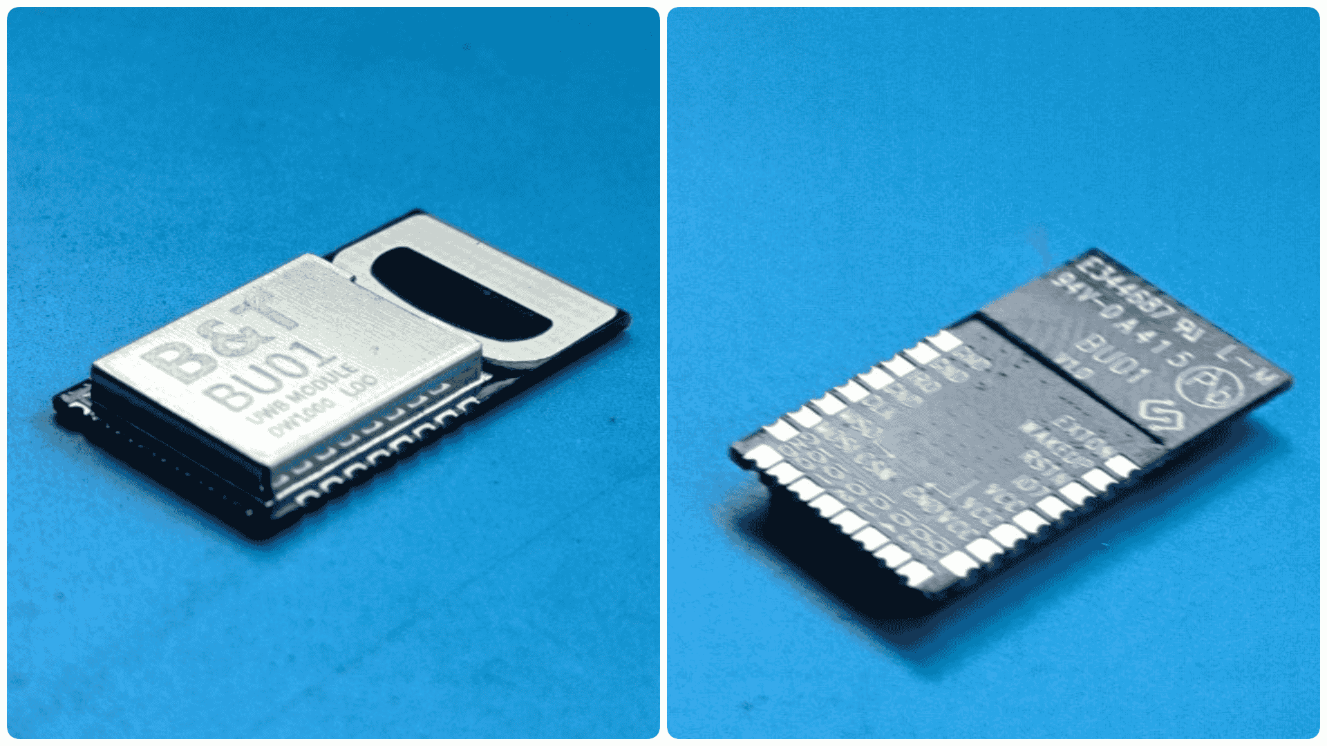
BU01
Link : https://www.digikey.in/en/products/detail/ai-thinker/BU01
The BU01 is an Ultra-Wideband (UWB) transceiver module developed by Ai-Thinker, based on the Decawave DW1000 chip. It supports the IEEE 802.15.4-2011 UWB standard, enabling high-precision positioning with an accuracy of up to 10 cm and a data rate of up to 6.8 Mbps. The module operates in the 3.5 GHz – 6.5 GHz frequency range and communicates via an SPI interface, making it compatible with various microcontrollers. It features low power consumption, an integrated PCB antenna, and supports ranging techniques like Two-Way Ranging (TWR) and Time Difference of Arrival (TDOA) for real-time location tracking. With its compact design and robust performance, the BU01 is ideal for applications such as indoor positioning, asset tracking, smart access control, and IoT solutions.
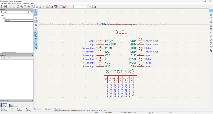
BU02 pin Out
Data sheet link : BU01 data sheet
| Pin No. | Name | Function Description |
|---|---|---|
| 1 | EXTON | Enables external devices, remains active during wake-up. Can control external DC-DC converters to save power. |
| 2 | WAKEUP | Wakes up DW1000 from SLEEP/DEEPSLEEP when set high. If unused, connect to GND. |
| 3 | RSTn | Active-low reset pin. Can be pulled low to reset the module. |
| 4 | IO7 | Default SYNC input. Can be configured as GPIO7. |
| 5 | VCC | 3.3V power supply |
| 6 | VCC | 3.3V power supply |
| 7 | VCC | 3.3V power supply |
| 8 | GND | Ground |
| 9 | IO6 | General I/O. At power-up, used as SPI Phase Select (SPIPHA). |
| 10 | IO5 | General I/O. At power-up, used as SPI Polarity Select (SPIPOL). |
| 11 | IO4 | General-purpose I/O pin. |
| 12 | IO3 | General-purpose I/O pin. Can be used as TX LED driver. |
| 13 | IO2 | General-purpose I/O pin. Can be used as RX LED driver. |
| 14 | IO1 | General-purpose I/O pin. Can be used as SFD LED driver (lights up on Start Frame Delimiter detection). |
| 15 | IO0 | General-purpose I/O pin. Can be used as RXOK LED driver (lights up when a valid frame is received). |
| 16 | GND | Ground |
| 17 | CSn | SPI Chip Select (Active Low). Also used to wake the module from sleep. |
| 18 | MOSI | SPI Data Input |
| 19 | MISO | SPI Data Output |
| 20 | CLK | SPI Clock |
| 21 | GND | Ground |
| 22 | IRQ | Interrupt Output from DW1000 to the host processor. Can be reconfigured as GPIO8. |
| 23 | GND | Ground |
| 24 | GND | Ground |
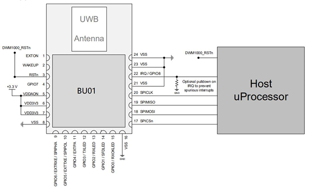
Image source: BU01 data sheet
Design
For this weeks assignment i am using BU01 but KIcad library and foot prints were not available, so i had to export ith from EasyEDA am convert it so that it can work on KIcad, And also convert the footprint so that it can be used in KiCad and also i had to import cad model from grab cad and I have linked a zip file which contains all the files here.
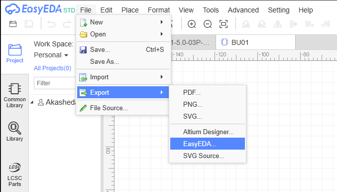
For exporting foot print and symbols from EasyEDA to KiCad I have used the following steps
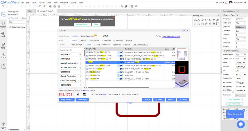
1. Open the Foot print & Symbol in EasyEDA from the library section an click on the edit option then In files go to export and export the file as json file
2. Now open the json file in KiCad's symbol editor or Footprint Editor depending on the file. and them save it.
3. while editing hte symbols i had to add the electric type depending on the pin for all the pins.
4. And follow the standard steps for library and footprints and make sure to save the files in the same directory in the so it will be easy.
Link : BU01 KICAD library
Address Assigning
To set up a UWB network with the ESP32 and DW1000 modules, I used two key lines of code:
DW1000.setDeviceAddress(x);  // Sets a unique address for each board
DW1000.setNetworkId(y);      // Assigns the boards to the same network
Each UWB board must have a unique device address so they can identify and communicate with one another. For example, I assigned:
- Anchor 1 → Address 1
- Anchor 2 → Address 2
- Tag → Address 5
All of these boards were given the same network ID (e.g., 10) using DW1000.setNetworkId(10);. This ensures they are part of the same communication group.
This addressing system is what forms the basic UWB network, where the tag can send ranging requests, and the anchors respond based on their addresses. It’s like giving each board a name and putting them all in the same room so they can talk to each other.
This is how I built a simple and functional UWB network during Networking Week.
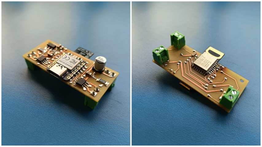
Board 1
For the pin out i have referred and existing boards documentations for the pin out
Source : ESP32 UWB(Ultra Wideband)
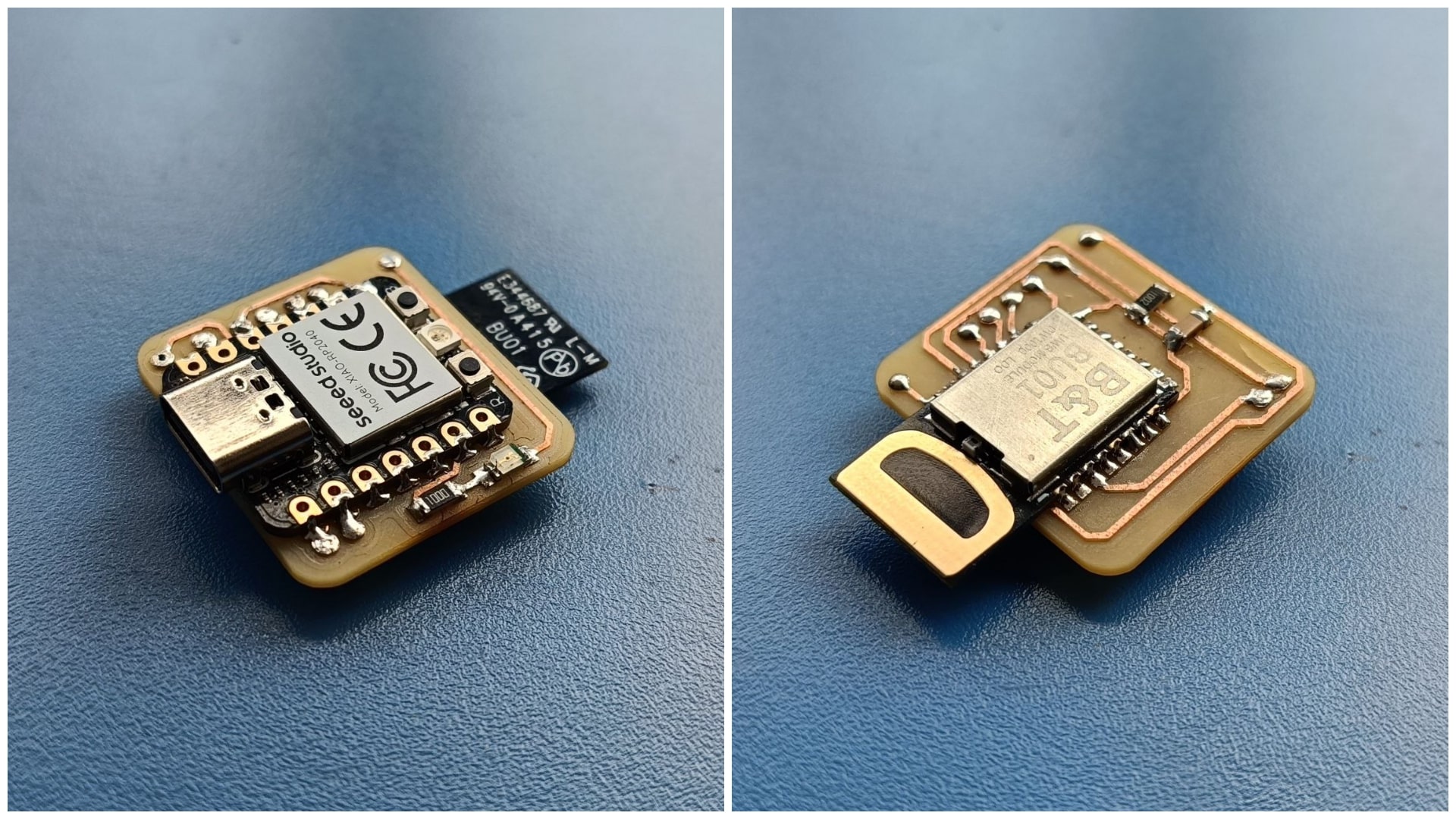
For this weeks assignment my plan was to design a compact board which have the BU01 mounted on it and connect it to a microcontroller.My first plan was to use an ATtiny1614, But is working voltage was 5V and the BU01 max working voltage was 3.6V so i would have to add a seporate voltage regulator circuit and programming pins to avoid this problem I an using the seed studio RP2040 & I have als added an LED to the circuit for debugging.
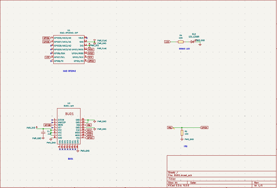
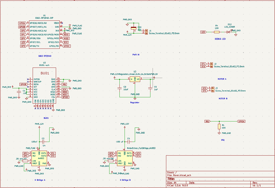
The schematic was designed using the kiCad. The design was done in a way that the BU01 module is connected to the RP2040 microcontroller, which will handle the communication and processing tasks. The LED is connected to one of the GPIO pins of the RP2040 for debugging purposes.And for making the board compact I Placed the BU01 module on the bottom of the board.And also made sure that the antenna is kept out side the board to avoid anu interferences.
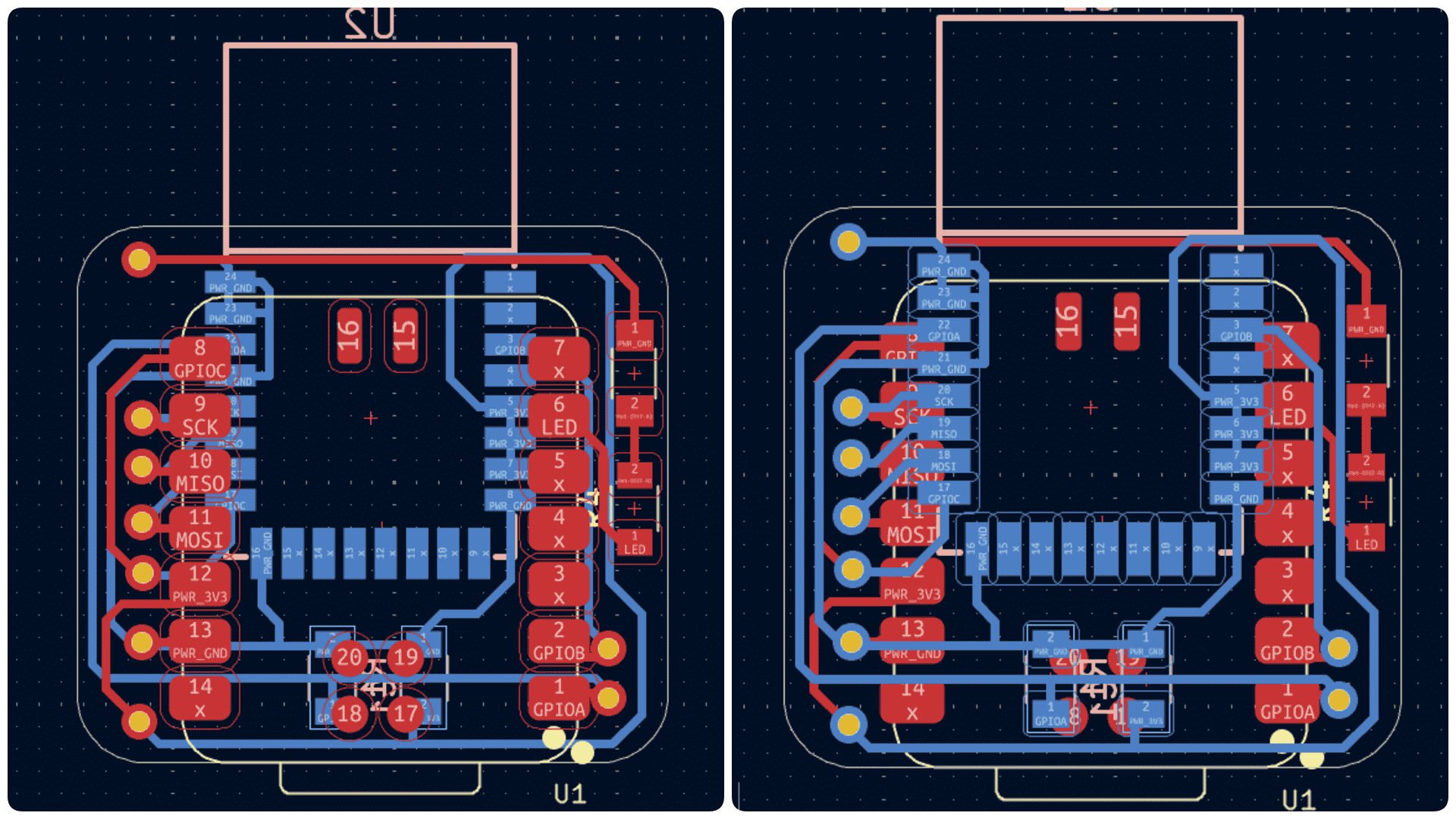
Since i am using a multi sided board i had to use rivets but the rivets available here are thick and cannot be paced under the components if it was not the case i could have made the boards more compact.
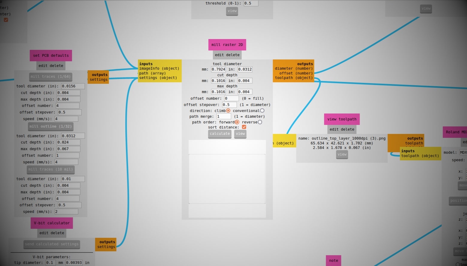
Since it is a very small board i removed all the islands using the miller itself.For this load the bigger tool and set the max depth and cut dept to required value and also set the off set nuber to 0 as shown in the image below.
After this i used the 1/32 inch end mill to cut the board and the 1/64 inch end mill to cut the traces.on both sides and drill holes for the rivets.And after soldering this is the final out put.
This is the 3D model of the board which was exported from kiCad
Testing
The board was tested using the Arduino IDE and the arduino-dw1000 library was used to communicate with the BU01 module.For this I used the example code provided by the library.Then the board was working
library link : https://github.com/Seeed-Studio/arduino-dw1000
      #include <SPI.h>
        #include <DW1000.h>

        // connection pins
        const uint8_t PIN_RST =D1; // reset pin
        const uint8_t PIN_IRQ = D0; // irq pin
        const uint8_t PIN_SS = D7; // spi select pin

        void setup() {
          // DEBUG monitoring
          Serial.begin(9600);
          // initialize the driver
          DW1000.begin(PIN_IRQ, PIN_RST);
          DW1000.select(PIN_SS);
          Serial.println(F("DW1000 initialized ..."));
          // general configuration
          DW1000.newConfiguration();
          DW1000.setDeviceAddress(5);
          DW1000.setNetworkId(10);
          DW1000.commitConfiguration();
          Serial.println(F("Committed configuration ..."));
          // wait a bit
          delay(1000);
        }

        void loop() {
          // DEBUG chip info and registers pretty printed
          char msg[128];
          DW1000.getPrintableDeviceIdentifier(msg);
          Serial.print("Device ID: "); Serial.println(msg);
          DW1000.getPrintableExtendedUniqueIdentifier(msg);
          Serial.print("Unique ID: "); Serial.println(msg);
          DW1000.getPrintableNetworkIdAndShortAddress(msg);
          Serial.print("Network ID & Device Address: "); Serial.println(msg);
          DW1000.getPrintableDeviceMode(msg);
          Serial.print("Device mode: "); Serial.println(msg);
          // wait a bit
          delay(10000);
        }
When I tried uploading the second program to to send signal was not working. I tested it multiple times and there was some issuer with the board.
      #include <SPI.h>
        #include <DW1000.h>

        // connection pins
        const uint8_t PIN_RST = 27; // reset pin
        const uint8_t PIN_IRQ = 26; // irq pin
        const uint8_t PIN_SS = 1; // spi select pin

        // DEBUG packet sent status and count
        boolean sent = false;
        volatile boolean sentAck = false;
        volatile unsigned long delaySent = 0;
        int16_t sentNum = 0; // todo check int type
        DW1000Time sentTime;

        void setup() {
          // DEBUG monitoring
          Serial.begin(9600);
          Serial.println(F("### DW1000-arduino-sender-test ###"));
          // initialize the driver
          DW1000.begin(PIN_IRQ, PIN_RST);
          DW1000.select(PIN_SS);
          Serial.println(F("DW1000 initialized ..."));
          // general configuration
          DW1000.newConfiguration();
          DW1000.setDefaults();
          DW1000.setDeviceAddress(5);
          DW1000.setNetworkId(10);
          DW1000.enableMode(DW1000.MODE_LONGDATA_RANGE_LOWPOWER);
          DW1000.commitConfiguration();
          Serial.println(F("Committed configuration ..."));
          // DEBUG chip info and registers pretty printed
          char msg[128];
          DW1000.getPrintableDeviceIdentifier(msg);
          Serial.print("Device ID: "); Serial.println(msg);
          DW1000.getPrintableExtendedUniqueIdentifier(msg);
          Serial.print("Unique ID: "); Serial.println(msg);
          DW1000.getPrintableNetworkIdAndShortAddress(msg);
          Serial.print("Network ID & Device Address: "); Serial.println(msg);
          DW1000.getPrintableDeviceMode(msg);
          Serial.print("Device mode: "); Serial.println(msg);
          // attach callback for (successfully) sent messages
          DW1000.attachSentHandler(handleSent);
          // start a transmission
          transmitter();
        }

        void handleSent() {
          // status change on sent success
          sentAck = true;
        }

        void transmitter() {
          // transmit some data
          Serial.print("Transmitting packet ... #"); Serial.println(sentNum);
          DW1000.newTransmit();
          DW1000.setDefaults();
          String msg = "Hello DW1000, it's #"; msg += sentNum;
          DW1000.setData(msg);
          // delay sending the message for the given amount
          DW1000Time deltaTime = DW1000Time(10, DW1000Time::MILLISECONDS);
          DW1000.setDelay(deltaTime);
          DW1000.startTransmit();
          delaySent = millis();
        }

        void loop() {
          if (!sentAck) {
            return;
          }
          // continue on success confirmation
          // (we are here after the given amount of send delay time has passed)
          sentAck = false;
          // update and print some information about the sent message
          Serial.print("ARDUINO delay sent [ms] ... "); Serial.println(millis() - delaySent);
          DW1000Time newSentTime;
          DW1000.getTransmitTimestamp(newSentTime);
          Serial.print("Processed packet ... #"); Serial.println(sentNum);
          Serial.print("Sent timestamp ... "); Serial.println(newSentTime.getAsMicroSeconds());
          // note: delta is just for simple demo as not correct on system time counter wrap-around
          Serial.print("DW1000 delta send time [ms] ... "); Serial.println((newSentTime.getAsMicroSeconds() - sentTime.getAsMicroSeconds()) * 1.0e-3);
          sentTime = newSentTime;
          sentNum++;
          // again, transmit some data
          transmitter();
        }
I also tried uploading the receive code in the same board this was also not working.
      #include <SPI.h>
        #include <DW1000.h>

        // connection pins
        const uint8_t PIN_RST = 27; // reset pin
        const uint8_t PIN_IRQ = 26; // irq pin
        const uint8_t PIN_SS = 1; // spi select pin

        // DEBUG packet sent status and count
volatile boolean received = false;
volatile boolean error = false;
volatile int16_t numReceived = 0; // todo check int type
String message;

void setup() {
  // DEBUG monitoring
  Serial.begin(9600);
  Serial.println(F("### DW1000-arduino-receiver-test ###"));
  // initialize the driver
  DW1000.begin(PIN_IRQ, PIN_RST);
  DW1000.select(PIN_SS);
  Serial.println(F("DW1000 initialized ..."));
  // general configuration
  DW1000.newConfiguration();
  DW1000.setDefaults();
  DW1000.setDeviceAddress(6);
  DW1000.setNetworkId(10);
  DW1000.enableMode(DW1000.MODE_LONGDATA_RANGE_LOWPOWER);
  DW1000.commitConfiguration();
  Serial.println(F("Committed configuration ..."));
  // DEBUG chip info and registers pretty printed
  char msg[128];
  DW1000.getPrintableDeviceIdentifier(msg);
  Serial.print("Device ID: "); Serial.println(msg);
  DW1000.getPrintableExtendedUniqueIdentifier(msg);
  Serial.print("Unique ID: "); Serial.println(msg);
  DW1000.getPrintableNetworkIdAndShortAddress(msg);
  Serial.print("Network ID & Device Address: "); Serial.println(msg);
  DW1000.getPrintableDeviceMode(msg);
  Serial.print("Device mode: "); Serial.println(msg);
  // attach callback for (successfully) received messages
  DW1000.attachReceivedHandler(handleReceived);
  DW1000.attachReceiveFailedHandler(handleError);
  DW1000.attachErrorHandler(handleError);
  // start reception
  receiver();
}

void handleReceived() {
  // status change on reception success
  received = true;
}

void handleError() {
  error = true;
}

void receiver() {
  DW1000.newReceive();
  DW1000.setDefaults();
  // so we don't need to restart the receiver manually
  DW1000.receivePermanently(true);
  DW1000.startReceive();
}

void loop() {
  // enter on confirmation of ISR status change (successfully received)
  if (received) {
    numReceived++;
    // get data as string
    DW1000.getData(message);
    Serial.print("Received message ... #"); Serial.println(numReceived);
    Serial.print("Data is ... "); Serial.println(message);
    Serial.print("FP power is [dBm] ... "); Serial.println(DW1000.getFirstPathPower());
    Serial.print("RX power is [dBm] ... "); Serial.println(DW1000.getReceivePower());
    Serial.print("Signal quality is ... "); Serial.println(DW1000.getReceiveQuality());
    received = false;
  }
  if (error) {
    Serial.println("Error receiving a message");
    error = false;
    DW1000.getData(message);
    Serial.print("Error data is ... "); Serial.println(message);
  }
}
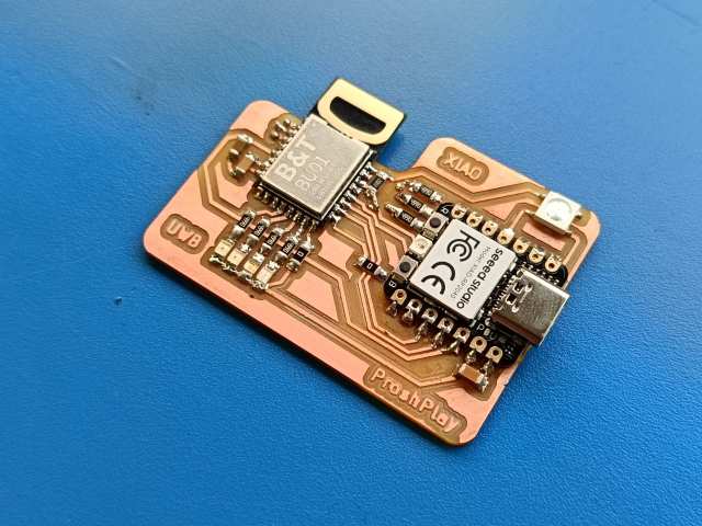
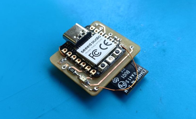
Board 2
The second board contains 2 H bridge to drive 2 DC motor,voltage regulator circuit, Debug LED, BU01 and an RP2040, This is a aboard that can be used for my final project to drive the robot.And it can communicate with the first board to get the the distance from it, And by using multiple Nodes i an get position data in 2D & 3D with 10 cm accuracy.
This is the schematic of the second board.
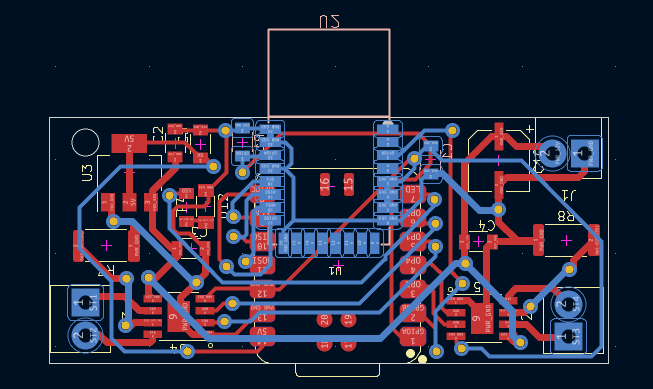
This is the layout of the second board.I had to use a multi sided PCB due to the complexity of connection the pins from BU01 to RP2040 and i have added screw terminal for each motor and the powerIN.I have also provided a screw hole so that the board can be mounted on the robot.
This is the 3D model of the board which was exported from kiCad
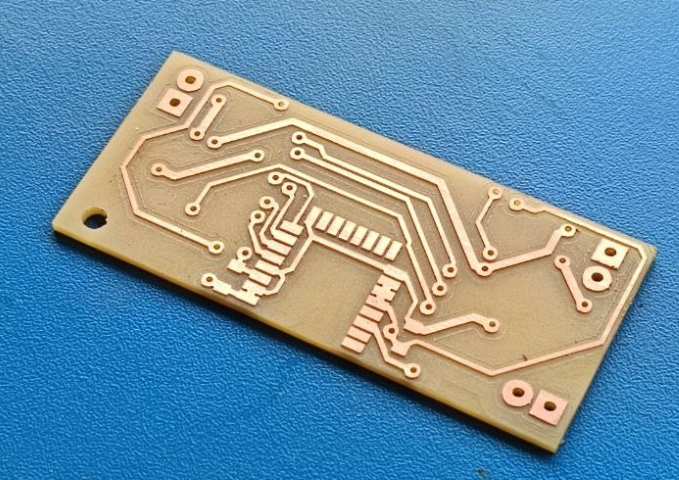
This is the PCB after milling.
This is the PCB after soldering the components.
This is the PCB was designed taking reference from the board 1 and the board from week 10 and when i tested this board it was working as expected
since my first board was not working as expected my instructor Saheen made a seporate bord so i used that board as my second board since there was no time left make a new board.
Git Link : Xiao_RP2040_UWB-BU01_Anchor-Node
Then I used the send and received code given above to test the board & It was working as expected,I was a very happy moment for me since i have spend a lot of time finding the issue.
Then I tested the distance measurement using BU01 using the example code from the library.In one board I uploaded the Anchor code where the distance data is receive.
      #include <SPI.h>
      #include <DW1000.h>

      // connection pins
      const uint8_t PIN_RST = 27; // reset pin
      const uint8_t PIN_IRQ = 26; // irq pin
      const uint8_t PIN_SS = 1; // spi select pin

      // messages used in the ranging protocol
      // TODO replace by enum
      #define POLL 0
      #define POLL_ACK 1
      #define RANGE 2
      #define RANGE_REPORT 3
      #define RANGE_FAILED 255
      // message flow state
      volatile byte expectedMsgId = POLL;
      // message sent/received state
      volatile boolean sentAck = false;
      volatile boolean receivedAck = false;
      // protocol error state
      boolean protocolFailed = false;
      // timestamps to remember
      DW1000Time timePollSent;
      DW1000Time timePollReceived;
      DW1000Time timePollAckSent;
      DW1000Time timePollAckReceived;
      DW1000Time timeRangeSent;
      DW1000Time timeRangeReceived;
      // last computed range/time
      DW1000Time timeComputedRange;
      // data buffer
      #define LEN_DATA 16
      byte data[LEN_DATA];
      // watchdog and reset period
      uint32_t lastActivity;
      uint32_t resetPeriod = 250;
      // reply times (same on both sides for symm. ranging)
      uint16_t replyDelayTimeUS = 3000;
      // ranging counter (per second)
      uint16_t successRangingCount = 0;
      uint32_t rangingCountPeriod = 0;
      float samplingRate = 0;

      void setup() {
          // DEBUG monitoring
          Serial.begin(115200);
          delay(1000);
          Serial.println(F("### DW1000-arduino-ranging-anchor ###"));
          // initialize the driver
          DW1000.begin(PIN_IRQ, PIN_RST);
          DW1000.select(PIN_SS);
          Serial.println(F("DW1000 initialized ..."));
          // general configuration
          DW1000.newConfiguration();
          DW1000.setDefaults();
          DW1000.setDeviceAddress(1);
          DW1000.setNetworkId(10);
          DW1000.enableMode(DW1000.MODE_LONGDATA_RANGE_LOWPOWER);
          DW1000.commitConfiguration();
          Serial.println(F("Committed configuration ..."));
          // DEBUG chip info and registers pretty printed
          char msg[128];
          DW1000.getPrintableDeviceIdentifier(msg);
          Serial.print("Device ID: "); Serial.println(msg);
          DW1000.getPrintableExtendedUniqueIdentifier(msg);
          Serial.print("Unique ID: "); Serial.println(msg);
          DW1000.getPrintableNetworkIdAndShortAddress(msg);
          Serial.print("Network ID & Device Address: "); Serial.println(msg);
          DW1000.getPrintableDeviceMode(msg);
          Serial.print("Device mode: "); Serial.println(msg);
          // attach callback for (successfully) sent and received messages
          DW1000.attachSentHandler(handleSent);
          DW1000.attachReceivedHandler(handleReceived);
          // anchor starts in receiving mode, awaiting a ranging poll message
          receiver();
          noteActivity();
          // for first time ranging frequency computation
          rangingCountPeriod = millis();
      }

      void noteActivity() {
          // update activity timestamp, so that we do not reach "resetPeriod"
          lastActivity = millis();
      }

      void resetInactive() {
          // anchor listens for POLL
          expectedMsgId = POLL;
          receiver();
          noteActivity();
      }

      void handleSent() {
          // status change on sent success
          sentAck = true;
      }

      void handleReceived() {
          // status change on received success
          receivedAck = true;
      }

      void transmitPollAck() {
          DW1000.newTransmit();
          DW1000.setDefaults();
          data[0] = POLL_ACK;
          // delay the same amount as ranging tag
          DW1000Time deltaTime = DW1000Time(replyDelayTimeUS, DW1000Time::MICROSECONDS);
          DW1000.setDelay(deltaTime);
          DW1000.setData(data, LEN_DATA);
          DW1000.startTransmit();
      }

      void transmitRangeReport(float curRange) {
          DW1000.newTransmit();
          DW1000.setDefaults();
          data[0] = RANGE_REPORT;
          // write final ranging result
          memcpy(data + 1, &curRange, 4);
          DW1000.setData(data, LEN_DATA);
          DW1000.startTransmit();
      }

      void transmitRangeFailed() {
          DW1000.newTransmit();
          DW1000.setDefaults();
          data[0] = RANGE_FAILED;
          DW1000.setData(data, LEN_DATA);
          DW1000.startTransmit();
      }

      void receiver() {
          DW1000.newReceive();
          DW1000.setDefaults();
          // so we don't need to restart the receiver manually
          DW1000.receivePermanently(true);
          DW1000.startReceive();
      }

      /*
       * RANGING ALGORITHMS
       * ------------------
       * Either of the below functions can be used for range computation (see line "CHOSEN
       * RANGING ALGORITHM" in the code).
       * - Asymmetric is more computation intense but least error prone
       * - Symmetric is less computation intense but more error prone to clock drifts
       *
       * The anchors and tags of this reference example use the same reply delay times, hence
       * are capable of symmetric ranging (and of asymmetric ranging anyway).
       */

      void computeRangeAsymmetric() {
          // asymmetric two-way ranging (more computation intense, less error prone)
          DW1000Time round1 = (timePollAckReceived - timePollSent).wrap();
          DW1000Time reply1 = (timePollAckSent - timePollReceived).wrap();
          DW1000Time round2 = (timeRangeReceived - timePollAckSent).wrap();
          DW1000Time reply2 = (timeRangeSent - timePollAckReceived).wrap();
          DW1000Time tof = (round1 * round2 - reply1 * reply2) / (round1 + round2 + reply1 + reply2);
          // set tof timestamp
          timeComputedRange.setTimestamp(tof);
      }

      void computeRangeSymmetric() {
          // symmetric two-way ranging (less computation intense, more error prone on clock drift)
          DW1000Time tof = ((timePollAckReceived - timePollSent) - (timePollAckSent - timePollReceived) +
                            (timeRangeReceived - timePollAckSent) - (timeRangeSent - timePollAckReceived)) * 0.25f;
          // set tof timestamp
          timeComputedRange.setTimestamp(tof);
      }

      /*
       * END RANGING ALGORITHMS
       * ----------------------
       */

      void loop() {
          int32_t curMillis = millis();
          if (!sentAck && !receivedAck) {
              // check if inactive
              if (curMillis - lastActivity > resetPeriod) {
                  resetInactive();
              }
              return;
          }
          // continue on any success confirmation
          if (sentAck) {
              sentAck = false;
              byte msgId = data[0];
              if (msgId == POLL_ACK) {
                  DW1000.getTransmitTimestamp(timePollAckSent);
                  noteActivity();
              }
          }
          if (receivedAck) {
              receivedAck = false;
              // get message and parse
              DW1000.getData(data, LEN_DATA);
              byte msgId = data[0];
              if (msgId != expectedMsgId) {
                  // unexpected message, start over again (except if already POLL)
                  protocolFailed = true;
              }
              if (msgId == POLL) {
                  // on POLL we (re-)start, so no protocol failure
                  protocolFailed = false;
                  DW1000.getReceiveTimestamp(timePollReceived);
                  expectedMsgId = RANGE;
                  transmitPollAck();
                  noteActivity();
              }
              else if (msgId == RANGE) {
                  DW1000.getReceiveTimestamp(timeRangeReceived);
                  expectedMsgId = POLL;
                  if (!protocolFailed) {
                      timePollSent.setTimestamp(data + 1);
                      timePollAckReceived.setTimestamp(data + 6);
                      timeRangeSent.setTimestamp(data + 11);
                      // (re-)compute range as two-way ranging is done
                      computeRangeAsymmetric(); // CHOSEN RANGING ALGORITHM
                      transmitRangeReport(timeComputedRange.getAsMicroSeconds());
                      float distance = timeComputedRange.getAsMeters();
                      Serial.print("Range: "); Serial.print(distance); Serial.print(" m");
                      Serial.print("\t RX power: "); Serial.print(DW1000.getReceivePower()); Serial.print(" dBm");
                      Serial.print("\t Sampling: "); Serial.print(samplingRate); Serial.println(" Hz");
                      //Serial.print("FP power is [dBm]: "); Serial.print(DW1000.getFirstPathPower());
                      //Serial.print("RX power is [dBm]: "); Serial.println(DW1000.getReceivePower());
                      //Serial.print("Receive quality: "); Serial.println(DW1000.getReceiveQuality());
                      // update sampling rate (each second)
                      successRangingCount++;
                      if (curMillis - rangingCountPeriod > 1000) {
                          samplingRate = (1000.0f * successRangingCount) / (curMillis - rangingCountPeriod);
                          rangingCountPeriod = curMillis;
                          successRangingCount = 0;
                      }
                  }
                  else {
                      transmitRangeFailed();
                  }

                  noteActivity();
              }
          }
      }
Then in the second board I uploaded the Tag code that I got from the example code from the library.
    #include
    #include

    // connection pins
    const uint8_t PIN_RST = 9; // reset pin
    const uint8_t PIN_IRQ = 2; // irq pin
    const uint8_t PIN_SS = SS; // spi select pin

    // messages used in the ranging protocol
    // TODO replace by enum
    #define POLL 0
    #define POLL_ACK 1
    #define RANGE 2
    #define RANGE_REPORT 3
    #define RANGE_FAILED 255
    // message flow state
    volatile byte expectedMsgId = POLL_ACK;
    // message sent/received state
    volatile boolean sentAck = false;
    volatile boolean receivedAck = false;
    // timestamps to remember
    DW1000Time timePollSent;
    DW1000Time timePollAckReceived;
    DW1000Time timeRangeSent;
    // data buffer
    #define LEN_DATA 16
    byte data[LEN_DATA];
    // watchdog and reset period
    uint32_t lastActivity;
    uint32_t resetPeriod = 250;
    // reply times (same on both sides for symm. ranging)
    uint16_t replyDelayTimeUS = 3000;

    void setup() {
      // DEBUG monitoring
      Serial.begin(115200);
      Serial.println(F("### DW1000-arduino-ranging-tag ###"));
      // initialize the driver
      DW1000.begin(PIN_IRQ, PIN_RST);
      DW1000.select(PIN_SS);
      Serial.println("DW1000 initialized ...");
      // general configuration
      DW1000.newConfiguration();
      DW1000.setDefaults();
      DW1000.setDeviceAddress(2);
      DW1000.setNetworkId(10);
      DW1000.enableMode(DW1000.MODE_LONGDATA_RANGE_LOWPOWER);
      DW1000.commitConfiguration();
      Serial.println(F("Committed configuration ..."));
      // DEBUG chip info and registers pretty printed
      char msg[128];
      DW1000.getPrintableDeviceIdentifier(msg);
      Serial.print("Device ID: "); Serial.println(msg);
      DW1000.getPrintableExtendedUniqueIdentifier(msg);
      Serial.print("Unique ID: "); Serial.println(msg);
      DW1000.getPrintableNetworkIdAndShortAddress(msg);
      Serial.print("Network ID & Device Address: "); Serial.println(msg);
      DW1000.getPrintableDeviceMode(msg);
      Serial.print("Device mode: "); Serial.println(msg);
      // attach callback for (successfully) sent and received messages
      DW1000.attachSentHandler(handleSent);
      DW1000.attachReceivedHandler(handleReceived);
      // anchor starts by transmitting a POLL message
      receiver();
      transmitPoll();
      noteActivity();
    }

    void noteActivity() {
      // update activity timestamp, so that we do not reach "resetPeriod"
      lastActivity = millis();
    }

    void resetInactive() {
      // tag sends POLL and listens for POLL_ACK
      expectedMsgId = POLL_ACK;
      transmitPoll();
      noteActivity();
    }

    void handleSent() {
      // status change on sent success
      sentAck = true;
    }

    void handleReceived() {
      // status change on received success
      receivedAck = true;
    }

    void transmitPoll() {
      DW1000.newTransmit();
      DW1000.setDefaults();
      data[0] = POLL;
      DW1000.setData(data, LEN_DATA);
      DW1000.startTransmit();
    }

    void transmitRange() {
      DW1000.newTransmit();
      DW1000.setDefaults();
      data[0] = RANGE;
      // delay sending the message and remember expected future sent timestamp
      DW1000Time deltaTime = DW1000Time(replyDelayTimeUS, DW1000Time::MICROSECONDS);
      timeRangeSent = DW1000.setDelay(deltaTime);
      timePollSent.getTimestamp(data + 1);
      timePollAckReceived.getTimestamp(data + 6);
      timeRangeSent.getTimestamp(data + 11);
      DW1000.setData(data, LEN_DATA);
      DW1000.startTransmit();
      //Serial.print("Expect RANGE to be sent @ "); Serial.println(timeRangeSent.getAsFloat());
    }

    void receiver() {
      DW1000.newReceive();
      DW1000.setDefaults();
      // so we don't need to restart the receiver manually
      DW1000.receivePermanently(true);
      DW1000.startReceive();
    }

    void loop() {
      if (!sentAck && !receivedAck) {
          // check if inactive
          if (millis() - lastActivity > resetPeriod) {
              resetInactive();
          }
          return;
      }
      // continue on any success confirmation
      if (sentAck) {
          sentAck = false;
          byte msgId = data[0];
          if (msgId == POLL) {
              DW1000.getTransmitTimestamp(timePollSent);
              //Serial.print("Sent POLL @ "); Serial.println(timePollSent.getAsFloat());
          } else if (msgId == RANGE) {
              DW1000.getTransmitTimestamp(timeRangeSent);
              noteActivity();
          }
      }
      if (receivedAck) {
          receivedAck = false;
          // get message and parse
          DW1000.getData(data, LEN_DATA);
          byte msgId = data[0];
          if (msgId != expectedMsgId) {
              // unexpected message, start over again
              //Serial.print("Received wrong message # "); Serial.println(msgId);
              expectedMsgId = POLL_ACK;
              transmitPoll();
              return;
          }
          if (msgId == POLL_ACK) {
              DW1000.getReceiveTimestamp(timePollAckReceived);
              expectedMsgId = RANGE_REPORT;
              transmitRange();
              noteActivity();
          } else if (msgId == RANGE_REPORT) {
              expectedMsgId = POLL_ACK;
              float curRange;
              memcpy(&curRange, data + 1, 4);
              transmitPoll();
              noteActivity();
          } else if (msgId == RANGE_FAILED) {
              expectedMsgId = POLL_ACK;
              transmitPoll();
              noteActivity();
          }
      }
    }
Then I tested the distance measurement using BU01 using the example code from the library.In one board I uploaded the Anchor code where the distance data is receive.
These boards communicate using Ultra-Wideband (UWB) technology, allowing them to measure distances between each other with high precision by calculating the time-of-flight of radio signals. With this information and basic trigonometry, the relative positions of boards can be determined. When multiple UWB-enabled anchor boards are used, the system can estimate the 2D or 3D location of a tag (the moving board). The more anchors that are deployed, the more accurate the resulting position data becomes due to improved triangulation.
I am using the BU01 UWB module, which is based on the Decawave DW1000 chip. Communication between the microcontroller and the BU01 module is handled via the SPI (Serial Peripheral Interface). The microcontroller acts as the SPI master, sending and receiving data from the BU01 module to configure the chip, exchange timestamps, and handle ranging operations.
The DW1000.h library simplifies communication with the UWB module. One of its features is the automatic assignment of a unique device ID. When a board is initialized using this library, it retrieves the hardware’s unique ID from the DW1000 chip itself. This means you do not need to manually assign IDs to each board. During operation, this ID is used to identify the sender or receiver of messages in the UWB network. This allows multiple boards to be added to the system without requiring custom ID configurations, making setup and scaling much easier.
I initially tried using the UWB modules with the XIAO ESP32-C6, but encountered compatibility issues—likely due to the specific timing requirements or SPI implementation differences. I later switched to the XIAO RP2040, which successfully communicated with the BU01 using the DW1000.h library. I was able to retrieve position and distance data between nodes. However, the results were not very accurate, likely because I had only a minimal number of anchors in place. The accuracy and reliability of UWB localization improve significantly when using at least 4 or more well-placed anchors, especially for 3D tracking.
Failures
- First i made a mistake in the schematic and the board was not working as expected.so I had to make separately make connections.The chip select pin from BU01 should be connected to aa specific pin of the RP2040 i connected it to some other pin and it was not working as expected. Also I had give a pull up resistor to the reset pin which was not necessary.
Conclusion
I was able to send the distance data using the BU01. but the data was very in accurate. I was also able to learn about networking protocols and how they work. And I was able to explore the capabilities of the BU01. It was very challenging and there was lot of late night work and a lot of debugging.