week4. Embedded Programming
Assignment
Group assignment
- demonstrate and compare the toolchains and development workflows for available embedded architectures
Individual assignment
- browse through the data sheet for your microcontroller
- write a program for a microcontroller, and simulate its operation, to interact (with local input &/or output devices) and communicate (with remote wired or wireless connections)
- extra credit: test it on a development board
- extra credit: try different languages &/or development environments
Group assignment
For more information about group projects, please see the group project page on the FabLab Kannai website.
Group assignment page is here
Microcontroller RP2040 datasheet
I read the RP2040 datasheet while considering the specifications of the microcontroller needed for the Golgo 13 Machine that I will create for my final project.
Data Sheet Overview
1. Overview
- Processor core: Dual-core ARM Cortex-M0+
- Clock frequency: Up to 133 MHz
- On-chip memory: 264 KB SRAM
- External memory: QSPI flash (up to 16 MB)
2. Power Management
- Operating voltage: 1.8V to 3.3V
- Low-power modes: Supports multiple power-saving modes
3. Input/output (I/O)
- GPIO pins: 30 digital I/O pins
- PWM channels: 16 channels
- ADC: 3 channels of 12-bit ADC
- I2C: 2 I2C controllers
- SPI: 2 SPI controllers
- UART: 2 UART interfaces
4. Clocks and Timers
- Internal clock: 12 MHz RC oscillator
- External clock: External crystal or clock input (max. 24 MHz)
- Timers: 4 multi-channel timers
5. Debugging and Programming
- Debug interface: SWD (Serial Wire Debug)
- Programming interface: Bootloader via USB or UART
6. Peripherals
- PIO (Programmable I/O): Two independent PIO blocks, each block with four state machines
7. Power consumption
- Operating voltage: 1.8V to 3.3V
- Power saving mode: Supports multiple power saving modes
RP2040 Performance Assessment
The Golgo 13 Machine I am creating for my final project will receive information from the millimeter wave radar using the RP2040 and transmit it to a smartphone via WiFi. In conclusion, I found that the performance of the RP2040 is sufficient for transmitting information from the millimeter wave radar via WiFi. The details are as follows.
Dual-core processor:
- The RP2040 is equipped with a dual-core ARM Cortex-M0+ processor that operates at a maximum of 133 MHz. This high-performance processor has sufficient processing power to simultaneously process data from the millimeter-wave radar and perform WiFi communication.
Memory:
- The RP2040 has 264 KB of on-chip SRAM, which is sufficient capacity for temporary storage and processing of data. This allows the data from the millimeter wave radar to be processed efficiently and sent to the smartphone via WiFi.
Support for WiFi modules:
- The RP2040 itself does not have built-in WiFi functionality, but it is possible to use WiFi communication by connecting an external WiFi module (for example, an ESP8266 or ESP32 module). This makes it possible to send data from the millimeter wave radar to a smartphone.
Microcontroller programming
I used WOKWI, an online simulator for electronic work, to simulate it. However, since the RP2040 online simulator is still incomplete, I used the ESP32 simulator instead. I modified the ESP32 HTTPClient Jokes API Example in the ESP32 simulator, and changed the Jokes API from programming-related jokes API to setup + punchline-style jokes API. The reason for this is that the punchline of the programming-related jokes API was difficult to understand.
programming-related jokes API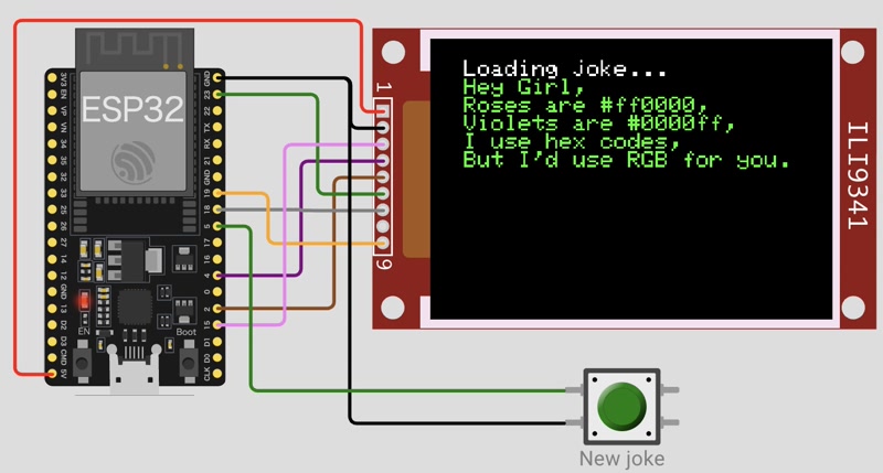
setup + punchline-style jokes API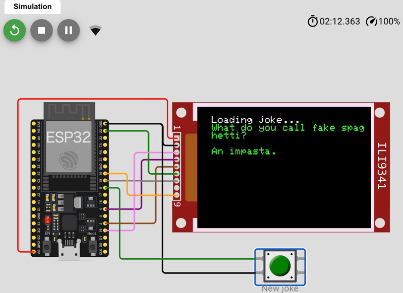
#include <WiFi.h>
#include <HTTPClient.h>
#include <ArduinoJson.h>
#include <Adafruit_GFX.h>
#include <Adafruit_ILI9341.h>

const char* ssid = "Wokwi-GUEST";
const char* password = "";

#define BTN_PIN 5
#define TFT_DC 2
#define TFT_CS 15
Adafruit_ILI9341 tft = Adafruit_ILI9341(TFT_CS, TFT_DC);

// setup + punchline style joke API
const String url = "https://official-joke-api.appspot.com/random_joke";

String getJoke() {
  HTTPClient http;
  http.useHTTP10(true);
  http.begin(url);
  int httpCode = http.GET();

  if (httpCode <= 0) {
    Serial.print("HTTP error: ");
    Serial.println(httpCode);
    http.end();
    return "<HTTP error>";
  }

  String result = http.getString();

  DynamicJsonDocument doc(1024);
  DeserializationError error = deserializeJson(doc, result);

  if (error) {
    Serial.print("JSON error: ");
    Serial.println(error.c_str());
    http.end();
    return "<parse error>";
  }

  String setup = doc["setup"].as<String>();
  String punchline = doc["punchline"].as<String>();
  http.end();

  return setup + "\n\n" + punchline;
}

void nextJoke() {
  tft.setTextColor(ILI9341_WHITE);
  tft.println("\nLoading joke...");

  String joke = getJoke();
  tft.setTextColor(ILI9341_GREEN);
  tft.println(joke);
}

void setup() {
  pinMode(BTN_PIN, INPUT_PULLUP);

  WiFi.begin(ssid, password, 6);

  tft.begin();
  tft.setRotation(1);

  tft.setTextColor(ILI9341_WHITE);
  tft.setTextSize(2);
  tft.print("Connecting to WiFi");

  while (WiFi.status() != WL_CONNECTED) {
    delay(100);
    tft.print(".");
  }

  tft.print("\nOK! IP=");
  tft.println(WiFi.localIP());

  nextJoke();
}

void loop() {
  if (digitalRead(BTN_PIN) == LOW) {
    tft.fillScreen(ILI9341_BLACK);
    tft.setCursor(0, 0);
    nextJoke();
  }

  delay(100);
}
As you can see below, the joke API has been switched to the setup + punchline format and is working fine. The jokes are now easier to understand!
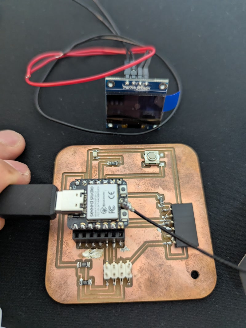
Testing on the Development Board
When I tried to run the ESP32 simulator code on the actual development board, I accidentally connected the GND and 3V3 pins of the OLED (SH1106) in reverse, which caused it to break. Therefore, I decided to cancel displaying jokes on the OLED and instead modified the program to print a joke to the serial console every five seconds and run it on the development board.
#include <WiFi.h>
#include <HTTPClient.h>
#include <ArduinoJson.h>

// Wi-Fi Configuration
const char* ssid = "*******";
const char* password = "*******";

// Joke API
const String url = "https://official-joke-api.appspot.com/random_joke";

// Joke acquisition interval (milliseconds)
const unsigned long interval = 5000;  // 5 sec.
unsigned long lastFetchTime = 0;

void setup() {
  Serial.begin(115200);
  Serial.println("Booting...");

  Serial.println("Connecting to WiFi...");
  WiFi.begin(ssid, password);
  while (WiFi.status() != WL_CONNECTED) {
    delay(500);
    Serial.print(".");
  }
  Serial.println("\nWiFi connected!");
  Serial.print("IP address: ");
  Serial.println(WiFi.localIP());

  // Get the first joke right away
  lastFetchTime = millis() - interval;
}

void loop() {
  unsigned long currentTime = millis();
  if (currentTime - lastFetchTime >= interval) {
    lastFetchTime = currentTime;
    String joke = getJoke();
    Serial.println("---- Joke ----");
    Serial.println(joke);
    Serial.println("--------------");
  }
}

String getJoke() {
  Serial.println("Fetching joke...");
  HTTPClient http;
  http.useHTTP10(true);
  http.begin(url);
  int httpCode = http.GET();

  if (httpCode <= 0) {
    Serial.print("HTTP error: ");
    Serial.println(httpCode);
    http.end();
    return "<HTTP error>";
  }

  String result = http.getString();
  http.end();

  DynamicJsonDocument doc(1024);
  DeserializationError error = deserializeJson(doc, result);

  if (error) {
    Serial.print("JSON parse error: ");
    Serial.println(error.c_str());
    return "<parse error>";
  }

  String setup = doc["setup"].as<String>();
  String punchline = doc["punchline"].as<String>();

  return setup + "\n\n" + punchline;
}Afterthoughts
- Incorrect pin connections can be very dangerous! I realized that pin connections should be done with great care.